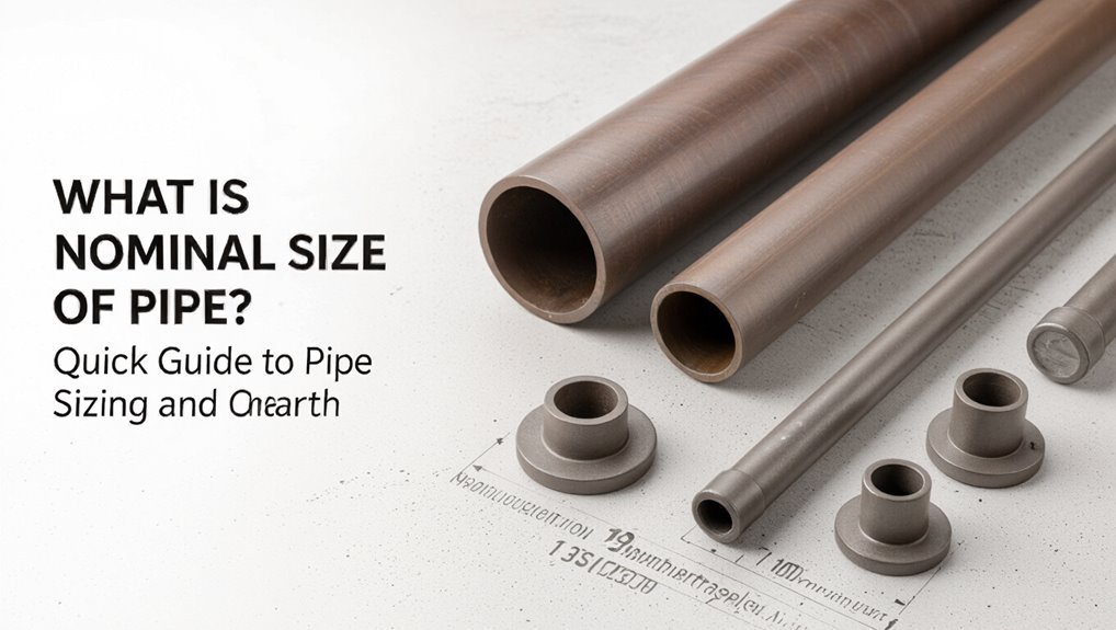
What Is Nominal Size of Pipe? Quick Guide to Pipe Sizing and Charts
Nominal pipe size is a standardized designation that indicates a pipe’s general capacity and compatibility with fittings rather than providing precise measurements. It was developed for convenience, aligning with traditional dimensions and fitting types. Each nominal size has a fixed outside diameter, while the inside diameter varies based on wall thickness (schedule). For specific details such as outside diameter, inside diameter, pressure ratings, and fitting compatibility, users should refer to manufacturer tables. Continue reading for practical charts, the impact of schedule on dimensions, and tips for ensuring compatibility.
Quick Answer: What Nominal Pipe Size Means
Nominal pipe size is a labeling convention that indicates a pipe’s approximate inside or outside diameter rather than its exact measurement; it serves as a quick reference for selecting fittings and matching components.
It provides a standardized designation—such as 1/2″, 1″, or 4″—used across specifications, catalogs, and drawings.
Nominal size groups pipes by capacity and compatibility, simplifying procurement and system design.
Manufacturers pair nominal sizes with schedules or series that define wall thickness and pressure capability.
For practical selection, professionals consult nominal size alongside material, schedule, and application requirements to guarantee proper performance and interoperability.
Why Nominal Size ≠ Actual Diameter
Why does a pipe’s common label not match its measured diameter? The nominal size is a historical designation used for identification and compatibility, not a literal measurement. It references a standardized system where names reflect approximate dimensions or mating fittings rather than actual outside or inside diameters.
Manufacturing conventions, material type and long-established sizing charts preserve these nominal values. Users rely on tables to translate nominal size to actual outside diameter and internal capacity. This separation simplifies interchangeability across producers and eras but requires consultation of specifications when precise dimensions or flow characteristics matter.
How Pipe Schedule and Wall Thickness Affect ID
Several factors determine a pipe’s internal diameter, but wall thickness—expressed through the pipe schedule—plays the primary role: thicker walls reduce the inside diameter (ID) for a given outside diameter (OD), while thinner walls increase it. The schedule number correlates to wall thickness; common schedules (e.g., 40, 80) change ID noticeably despite unchanged OD. Material and manufacturing tolerances also influence ID slightly. Designers choose schedule based on pressure, temperature, and flow requirements; higher pressure demands thicker walls, reducing flow area. Refer to manufacturer tables for exact IDs when selecting pipe schedule versus required hydraulic capacity.
| Schedule | Effect on ID |
|---|---|
| 10 | Larger ID |
| 40 | Moderate ID |
| 80 | Smaller ID |
| XS | Smallest ID |
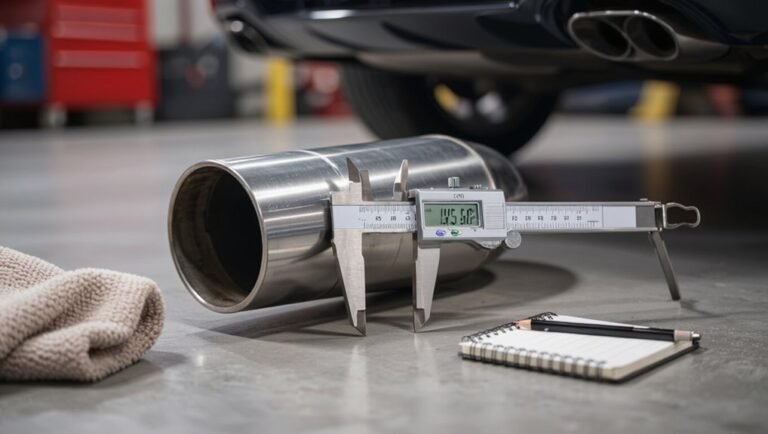
How to Read a Pipe Sizing Chart
With wall thickness and schedule understood, reading a pipe sizing chart becomes a matter of matching required hydraulic and mechanical parameters to the charted values.
The reader locates the nominal size column, then compares outside diameter, internal diameter, and wall thickness entries to the system requirements.
Flow rate and velocity columns determine acceptable pipe sizes for hydraulic performance; pressure rating and allowable stress guide mechanical suitability.
Temperature-corrected pressure limits and material designations must be checked next.
Cross-reference fittings and flange dimensions when installations require mating components.
Finally, select the smallest size meeting all constraints to balance cost, weight, and performance.
Common Nominal Sizes With OD and ID (¼”–12″)
For common nominal pipe sizes ranging from 1/4″ to 12″, standard tables list the nominal size alongside the corresponding outside diameter (OD) and nominal internal diameter (ID) for each wall thickness or schedule.
The listing begins at 1/4″, progressing through fractional and whole-inch NPS values to 12″.
Each entry shows fixed OD for a given nominal size, while ID varies with schedule (thicker walls reduce ID).
Typical charts include NPS, OD, and IDs for schedules 5S, 10S, 40, 80, etc., enabling selection based on flow requirements, pressure rating, and material compatibility without converting units.
Converting NPS to DN and Millimeters
Having shown how nominal pipe sizes map to fixed outside diameters and schedule-dependent internal diameters, the discussion shifts to converting North American NPS (Nominal Pipe Size) designations into metric DN (Diameter Nominal) and exact millimeter dimensions.
NPS labels are historical nominal values; DN is a rounded metric equivalent often matching the NPS nominal number multiplied by 25 (e.g., 2″ ≈ DN50).
Conversion tables match NPS to DN and list precise outside diameter in millimeters.
Engineers use these tables rather than simple multiplication because OD and wall thickness standards produce non‑integer millimeter sizes and guarantee compatibility across systems.
Choosing a Nominal Size for Flow and Pressure
In selecting a nominal pipe size, the engineer balances required flow capacity, allowable pressure drop, and the system’s operating pressure to arrive at a size that meets hydraulic and mechanical constraints.
The process evaluates target velocity ranges to avoid erosion or sedimentation, Reynolds number for laminar/turbulent regimes, and head loss using the Darcy–Weisbach or Hazen–Williams equations.
Material, temperature, and corrosion allowances influence wall thickness and maximum working pressure, affecting size selection.
Economic trade-offs between larger pipes (lower pumping costs) and material/installation costs are assessed.
Final selection follows applicable codes and verifies pump and valve compatibility.
Fittings and Nominal Pipe Size: NPT, BSP, Victaulic
The section contrasts common fitting standards and their impact on nominal pipe size selection.
It notes that NPT threads are tapered and generally incompatible with BSP without adapters, affecting sealing and pressure ratings.
It also highlights that Victaulic grooved couplings use a different joining principle and dimensions, so BSP and NPT fittings are not directly interchangeable with Victaulic systems.
NPT Thread Compatibility
Comparing thread standards clarifies how NPT fittings interface with BSP and Victaulic systems, since variations in thread form, taper, and sealing method determine compatibility and leak risk. NPT (National Pipe Taper) uses a tapered male/female thread and relies on thread deformation plus sealant for pressure-tight joints. NPT will not reliably mate with BSPP (parallel) or BSPT (taper) without adapters; mismatching thread angle and pitch causes leaks or damage. Victaulic is a grooved coupling system and is mechanically incompatible with threaded NPT without adapter fittings. Appropriate adapters or dedicated components are required for safe, leak-free connections.
| Standard | Thread Type | Compatibility Note |
|---|---|---|
| NPT | Tapered 60° | Seals with tape/compound |
| BSP | Parallel/tapered 55° | Different pitch/angle |
| Victaulic | Grooved coupling | Requires adapter |
Victaulic And BSP Differences
When examining Victaulic and BSP systems, notable differences in coupling method, sealing approach, and how nominal pipe size (NPS) is applied affect interchangeability and specifying fittings. Victaulic uses grooved-end couplings with gaskets and bolts, enabling quick assembly and axial flexibility; BSP relies on threaded connections (parallel BSPP or tapered BSPT) with thread sealing.
Victaulic sizing references groove standards matched to pipe OD and wall, while BSP follows nominal pipe size with thread geometry. These distinctions influence pressure ratings, leak potential, maintenance, and compatibility; adapters or careful specification are required when mixing systems.
- A sense of urgency about correct selection
- Confidence from engineered fit
- Concern over mismatched parts
Troubleshooting Mismatches and Fitting Fixes
Addressing mismatches and faulty fittings requires a systematic approach that isolates the source, evaluates compatibility, and applies the least invasive correction.
The inspector documents thread, diameter, material, and pressure class, then compares to standards and project specs.
Where threads or diameters differ, adapters or rework with approved couplings are selected; avoid forceful modifications that compromise integrity.
For seal failures, replace gaskets and use correct lubrication or sealant per material.
If corrosion or deformation exists, replace affected lengths and inspect adjacent joints.
Final testing verifies leak-free performance and records changes for future maintenance and compliance.
Conclusion
Understanding nominal pipe size means more than a number on a blueprint; it’s a starting point that hides real diameters, schedules, and fitting quirks. Knowing how OD, ID, schedule, and standards interact can prevent costly mismatches—yet one critical measurement often gets overlooked. As a project deadline looms, the wrong detail can ripple through procurement, installation, and pressure testing; only careful checking of charts, standards, and fittings will reveal whether the system will truly hold.