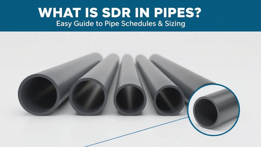
What Is SDR in Pipes? Easy Guide to Pipe Schedules & Sizing
SDR (Standard Dimension Ratio) is a crucial measurement in the world of piping, defined as the ratio of a pipe’s outside diameter to its wall thickness. It serves as an indicator of the pipe’s strength and pressure capacity: a lower SDR signifies a thicker wall and a higher pressure rating, whereas a higher SDR denotes a thinner wall with lower strength. Designers utilize SDR to effectively compare different pipes, align fittings, and establish pressure limits. The selection process is influenced by factors such as material, application, and testing requirements. This guide will further elaborate on how to convert and apply SDR in your projects.
What Is SDR (Standard Dimension Ratio) in Pipes
As a standardized metric for plastic and metal piping, Standard Dimension Ratio (SDR) expresses the relationship between a pipe’s outer diameter and its wall thickness, calculated by dividing the outer diameter by the wall thickness.
SDR is a dimensionless number; lower SDR values indicate thicker walls relative to diameter, higher values indicate thinner walls.
It provides a simple way to compare strength and pressure capability across pipe sizes and materials without referencing specific materials or schedules. Manufacturers list SDR alongside material properties and nominal diameters.
Selection of an SDR value informs expected mechanical performance, handling, and suitability for various pressure and load conditions.
Why SDR Matters for Pipe Design
Having established that SDR quantifies the ratio of a pipe’s outer diameter to its wall thickness, its importance in pipe design becomes clear: SDR directly influences pressure capacity, stiffness, and material usage.
Designers select SDR to match expected internal pressures and external loads; lower SDR (thicker wall) yields higher burst resistance and rigidity while higher SDR reduces material and cost but lowers allowable pressure.
SDR also affects long-term deflection, fatigue resistance, and joint performance under thermal or settlement stresses.
Proper SDR choice balances safety factors, service life, and economics, ensuring systems meet regulatory requirements and operational demands without unnecessary overspecification.
SDR vs Schedule and Nominal Size
How do SDR, Schedule, and nominal pipe size relate and differ? SDR (Standard Dimension Ratio) expresses the ratio of pipe outside diameter to wall thickness, indicating relative strength and flexibility.
Schedule is a numbering system that specifies wall thickness for given nominal pipe sizes, commonly used for metal and some plastics.
Nominal size is a designation representing an approximate inside or outside dimension, not the exact measurement.
SDR provides a comparative thinness independent of nominal labeling; schedule gives specific thickness values tied to nominal sizes.
Together they inform pressure rating, material selection, and compatibility, but they are distinct concepts.
SDR Formula: Diameter ÷ Wall Thickness
In pipe engineering, the Standard Dimension Ratio (SDR) is defined as the outside diameter of a pipe divided by its wall thickness, providing a single number that reflects relative wall slenderness.
The formula SDR = Dₒ / t yields an easy comparison across materials and sizes: larger SDR indicates thinner walls relative to diameter, smaller SDR indicates thicker walls.
Practitioners use nominal outside diameter and measured or specified wall thickness to compute SDR for design checks, selection, and quality control.
When exactness matters, values are calculated to appropriate significant figures and cross-referenced with standards to guarantee compatibility and pressure capability.
Why SDR Is a Unitless Ratio
Because SDR is formed by dividing an outside diameter by a wall thickness, the units of length cancel and the result is dimensionless.
The ratio compares two like quantities—both measured in length—so units such as inches or millimeters divide out, leaving a pure number.
This unitless nature makes SDR independent of measurement systems and convenient for universal specification.
It conveys geometry rather than physical units, enabling direct comparison across materials and sizes.
Designers and manufacturers rely on the numerical value to express relative wall thinness without attaching units, simplifying cataloging, communication, and conversion between imperial and metric practices.
How SDR Determines Pressure Rating
SDR directly links a pipe’s geometry to its ability to withstand internal pressure by expressing the ratio of diameter to wall thickness, which determines hoop stress for a given internal load.
Using thin‑wall hoop stress formula, allowable internal pressure inversely relates to SDR: higher SDR (larger diameter or thinner wall) yields greater stress and lower pressure capacity.
Material strength and temperature modify allowable stress, so design pressure = (2 × allowable stress × wall thickness) / diameter, effectively scaled by SDR.
Engineers select SDR to meet required pressure with safety factors, balancing weight, cost, and long‑term performance such as creep and fatigue.
Common SDRs: SDR11, SDR17 and Meanings
The article compares common SDRs, focusing first on SDR11 and its higher stiffness and typical applications requiring greater pressure resistance.
It then contrasts SDR17, noting its lower pressure rating and common uses where flexibility or cost savings matter.
Finally, guidance is offered on selecting the appropriate SDR based on required pressure, installation conditions, and longevity.
SDR11: Applications And Strength
Among common pressure-rated polyethylene pipe classifications, SDR11 strikes a balance between wall thickness and flow capacity, making it a frequent choice for water distribution, pressure mains, and irrigation systems.
It offers higher hoop stress resistance than larger SDR values, enabling operation at moderate to high internal pressures with relatively thinner walls than low-SDR options.
Its stiffness improves long-term dimensional stability and resistance to external loads while maintaining good hydraulic efficiency.
Typical applications include potable water conveyance, service lines, and medium-pressure industrial uses where durability and ease of installation matter.
Selection should consider temperature, joint type, and regulatory pressure ratings.
SDR17: Pressure And Uses
Moving from the higher-strength SDR11, SDR17 represents a thinner-walled, higher-diameter-to-thickness ratio option that suits lower-pressure applications where cost and flexibility matter more than maximum hoop strength.
SDR17 typically handles moderate working pressures in gravity, drainage, irrigation, and non-potable conveyance; it is common for buried utilities where impact resistance and ease of handling are priorities over high-pressure performance.
Design tables translate SDR17 into allowable hoop stress and pressure ratings for various materials and temperatures.
Installers select SDR17 when system pressures remain within its rated limits and when economic and installation benefits outweigh the need for thicker-walled alternatives.
Choosing The Right SDR
When selecting an SDR, engineers weigh pipe diameter, wall thickness, and expected service pressure to match performance with cost and installation constraints.
Choosing the right SDR balances strength and material economy: lower SDR (e.g., SDR11) yields thicker walls and higher pressure capacity; higher SDR (e.g., SDR17) offers thinner walls and lower pressure capability but reduced material cost and weight.
Selection considers fluid type, temperature, joint method, burial depth, regulatory requirements, and anticipated surge.
Designers consult manufacturer data and standards to verify allowable stress and safety factors.
Proper SDR choice minimizes failure risk while optimizing lifecycle cost and constructability.
Reading SDR on Pipe Markings
Reading SDR on pipe markings requires identifying the standard dimension ratio code stamped or printed along the pipe length; this code typically appears as “SDR” followed by a number (for example, SDR11) and indicates the ratio of pipe outside diameter to wall thickness.
Inspect nearby markings for manufacturer name, material type (e.g., PE, PVC), nominal size, and production date to confirm applicability.
Note orientation and repetition—codes repeat at intervals for visibility.
When multiple codes appear, prioritize the SDR matching the material specification.
Faded or missing markings warrant cross-referencing batch documents or contacting the supplier rather than assuming values.
Converting SDR to Wall Thickness (Step‑by‑Step)
To convert an SDR value into wall thickness, divide the pipe’s outside diameter (OD) by the SDR number: wall thickness = OD / SDR.
The procedure: confirm OD from specifications or measurement, note the SDR printed or charted, perform OD ÷ SDR to obtain nominal wall thickness.
Round per applicable standards or tooling tolerances; record units.
For multiple sizes compute individually and tabulate results.
For metric and imperial consistency convert units before calculation.
Verify results against manufacturer tables to account for manufacturing tolerances and design factors.
Use calculated thickness for pressure checks, but rely on certified data for final design decisions.
Quick Method: Wall Thickness to SDR
A simple shortcut lets the reader convert a known wall thickness into the corresponding SDR without reworking the full formula.
By comparing the measured thickness to the pipe’s outside diameter, the appropriate SDR can be determined quickly.
This method streamlines selection and verification when speed is more important than detailed calculation.
Convert Wall Thickness Easily
Using the known outside diameter and wall thickness, the pipe’s Standard Dimension Ratio (SDR) can be calculated quickly by dividing the outside diameter by twice the wall thickness and then rounding as appropriate for the SDR series in use; this direct algebraic approach converts measured dimensions into the standardized SDR value engineers and technicians require for pressure and material comparisons.
For field use, measure OD and wall thickness accurately, compute OD ÷ (2 × wall), and compare the result to the nearest standard SDR designation (e.g., SDR11, SDR17). Record units, confirm tolerances, and document the conversion method so results remain traceable and reproducible.
Determine SDR From Thickness
When given a pipe’s wall thickness and its outside diameter, the SDR can be found quickly by rearranging the SDR definition: SDR = OD ÷ (2 × wall thickness), then matching the calculated value to the nearest standard series designation (for example, SDR11, SDR17).
The practitioner computes OD and wall thickness in the same units, performs the division, and rounds to the closest published SDR value. If the result falls between series, select the lower SDR for higher pressure capability or consult manufacturer tables.
This quick method aids verification, specification checks, and field decisions without iterative strength or pressure calculations.
SDR and Pipe Material Differences (PE, PVC, PP)
Different pipe materials — polyethylene (PE), polyvinyl chloride (PVC), and polypropylene (PP) — interact with SDR (standard dimension ratio) in distinct ways that affect strength, flexibility, and application suitability.
PE, notably MDPE and HDPE, tolerates higher SDRs because its ductility and impact resistance compensate for thinner walls, making it common for flexible mains and trenchless installs.
PVC, being stiffer and more brittle, requires lower SDR (thicker walls) for pressure applications, favored in water distribution and sewer force mains.
PP balances flexibility and stiffness, allowing moderate SDRs for chemical and industrial piping.
Material selection with SDR therefore aligns mechanical properties to service conditions.
SDR and Long‑Term Hydrostatic Strength (LTHS)
In relation to long‑term hydrostatic strength (LTHS), SDR directly governs the wall thickness available to resist sustained internal pressure, making it a primary factor in a pipe’s rated lifetime performance.
SDR sets a constant geometric ratio that, combined with material properties and test-derived stress rupture data, yields a time‑to‑failure curve used for pressure rating.
Lower SDR (thicker walls) increases allowable stress for long durations; higher SDR reduces it.
Design uses LTHS tables or extrapolated stress rupture models to match service life and safety factors.
Proper selection balances SDR, expected pressure, and documented LTHS for the chosen polymer.
Temperature Effects on SDR Pressure Capacity
How does temperature alter a pipe’s SDR-based pressure capacity? Temperature affects polymer stiffness and creep, changing allowable stress and long-term strength. As temperature rises, wall material softens, reducing hydrostatic resistance and lowering pressure capacity for a given SDR. Conversely, colder conditions increase stiffness and momentary strength but may raise brittleness concerns.
Design standards apply temperature-dependent correction factors to adjust allowable working pressures; these factors reflect short- and long-term material behavior. Pipe selection and SDR choice must consider service temperature, fluid temperature, and ambient conditions to guarantee reliable performance, accounting for reduced margins at elevated temperatures and potential embrittlement at low temperatures.
Calculating Allowable Working Pressure From SDR
When calculating allowable working pressure from a pipe’s SDR, the process translates the nominal geometry and material strength into a usable pressure limit by combining the ring-stress formulation with material-dependent safety and temperature factors.
The practitioner uses SDR to determine wall thickness relative to diameter, applies the material’s long-term design stress and temperature derating, and inserts those values into the pressure equation to yield an allowable working pressure.
Factors of safety, joint efficiency, and applicable codes further modify the result.
The outcome guides selection and verification for service conditions, ensuring longevity and compliance without overdesign.
- Convert SDR to wall thickness and nominal diameter
- Apply material design stress and temperature factors
- Include safety and joint efficiency reductions
- Reference governing code or standard for final validation
Hoop Stress, SDR, and Structural Limits
Hoop stress is described as the circumferential tension developed in a pipe wall under internal pressure and is quantified by the classic thin-wall formula and its thicker-wall extensions.
SDR provides a compact way to link pipe geometry to expected hoop stress for a given internal pressure, with lower SDRs indicating greater resistance.
Comparing calculated hoop stresses to material yield and safety limits defines the structural boundaries for safe operating pressure.
Hoop Stress Basics
Relating internal pressure to wall thickness and material strength, hoop stress quantifies the circumferential tensile load in a pipe wall and is central to sizing and safety decisions.
It is calculated from internal pressure, pipe radius, and wall thickness, producing a value compared to allowable stress for the material.
Designers use hoop stress to set minimum thickness and select SDR that keeps stress below limits under operating conditions.
Temperature, long-term creep, and joint strength modify allowable values.
Understanding hoop stress informs inspection priorities and failure modes without substituting for full structural assessments.
- Basic formula: σh = (P·r)/t
- Material allowable stress
- Operational factors (temp, cycling)
- Safety margins and codes
SDR Vs. Structural Limits
After establishing how hoop stress links internal pressure, radius, and wall thickness, attention shifts to how Standard Dimension Ratio (SDR) choices interact with structural limits. SDR determines wall thickness for a given diameter; lower SDR means thicker wall and higher pressure capacity. Designers compare resulting hoop stress against material yield and long-term creep limits, factoring joint efficiency and temperature.
External loads—soil, traffic, burial depth—impose bending and collapse criteria that may govern SDR selection more than internal pressure. Safety factors reconcile uncertainties. Consequently SDR selection balances internal pressure capacity, structural resistance to external loads, material behavior, and manufacturing or installation constraints.
SDR Choices for Buried Water Mains
Selecting the appropriate Standard Dimension Ratio (SDR) for buried water mains balances hydraulic performance, structural capacity, and long-term durability. Designers choose SDR based on soil conditions, installation depth, internal pressure, and lifecycle costs. Lower SDR (thicker wall) increases resistance to external loads and pressure surges; higher SDR reduces material and installation cost but demands better bedding and restrained joints. Corrosion resistance, maintenance access, and fatigue under transient events also influence selection. Typical practice pairs conservative SDR with proven installation methods to minimize failure risk while optimizing flow.
- Match SDR to trench support and live loads
- Consider surge pressure margins
- Evaluate soil corrosivity and bedding
- Factor lifecycle and repair costs
SDR for Aboveground and Exposed Piping
Aboveground and exposed piping presents a different set of demands for SDR selection than buried mains, because environmental loading, thermal movement, and UV exposure replace soil support and embedment stresses as primary concerns.
Designers prioritize stiffness to resist wind, snow, and vibration while allowing for thermal expansion; a lower SDR (thicker wall) improves bending resistance and reduces deflection between supports.
UV-sensitive materials may require UV-stable compounds or coatings rather than relying on SDR alone.
Support spacing, anchoring, and expansion joints must align with chosen SDR to prevent overstress.
Chemical exposure and operating temperature also influence acceptable SDR choices.
SDR Recommendations for Sewer and Drainage
For sewer and drainage applications, recommended SDR values balance hydraulic performance with required strength for buried service loads.
Guidance should specify installation depth limits and bedding practices that preserve pipe structural integrity.
Material selection must also address chemical resistance and cyclic or point loads typical of wastewater and storm systems.
Recommended SDR Values
Recommended SDR values for sewer and drainage systems balance structural strength, hydraulic performance, and installation practicality.
Typical guidance favors lower SDR (thicker walls) for high loads or long spans and higher SDR for gravity mains with light cover. Material, pipe diameter, soil conditions, traffic loads, and design life determine selection. Common practice: choose SDR 11 for heavy-load or deep installations, SDR 17–21 for standard underground sewer mains, and SDR 26–41 for low-pressure or non-traffic areas where flexibility and cost matter.
Designers validate choice with codes and calculations to guarantee deflection limits and structural adequacy.
- Match SDR to soil and live loads
- Consider diameter-specific recommendations
- Follow local codes and standards
- Verify with structural calculations
Installation Depth Limits
When determining installation depth limits for sewer and drainage pipes, selection of SDR must account for overburden, live loads, and soil stiffness to guarantee wall thickness and stiffness prevent excessive deflection or collapse.
Designers evaluate burial depth against pipe stiffness class and anticipated settlement, matching SDR to computed ring stiffness requirements.
Greater depths typically require lower SDR (thicker walls) or enhanced bedding and backfill to reduce load transfer.
Installation guides give maximum depths per SDR for common diameters; deviations demand engineering verification.
Proper compaction, load distribution, and inspection confirm installed SDR performs as intended throughout service life.
Chemical And Load Resistance
Soil support, burial depth, and live loads are only part of SDR selection; chemical exposure and sustained internal or external pressures also govern appropriate wall thickness. The guidance for sewer and drainage recommends choosing SDR to resist corrosive effluents, hydrogen sulfide, and ground chemicals while maintaining deflection limits under long-term loads. Material compatibility, anticipated concentrations, and temperature influence SDR choices. Designers should reference pipe manufacturer chemical charts and industry standards for exposure classes for exposure classes. Where aggressive environments exist, select lower SDR (thicker walls) or chemically resistant compounds. Inspections and monitoring validate performance over service life.
- Assess effluent chemistry and pH
- Review temperature effects
- Compare material resistance charts
- Factor long-term load creep
SDR for Stormwater Systems
How does SDR influence the performance of stormwater systems? SDR determines wall thickness and stiffness, affecting hydraulic capacity, durability, and resistance to external loads. Lower SDR (thicker walls) improves structural performance under soil and traffic loading; higher SDR reduces material cost but may need bedding or encasement.
| Benefit | Impact |
|---|---|
| Hydraulic capacity | Smoother internal surface vs. structural deflection affects flow |
| Durability | Thicker walls resist deformation, abrasion, UV exposure |
Designers balance hydraulic needs, expected loads, installation conditions, and lifecycle costs. Proper SDR selection reduces maintenance and failure risk in stormwater networks.
SDR Selection for Gas and Pressure Mains
Selection of SDR for gas and pressure mains hinges on matching the pipe’s pressure rating to the system’s operating and peak pressures.
Material choice and its temperature-dependent strength influence allowable SDR and long-term performance.
Engineers must consequently weigh gas pressure ratings alongside material and temperature effects when specifying SDR.
Gas Pressure Ratings
Determine gas pressure ratings by matching SDR (Standard Dimension Ratio) to the required working pressure and safety factors for gas and pressure mains. The SDR chosen controls wall thickness relative to diameter, directly affecting allowable pressure and long‑term performance. Engineers select SDR by applying design pressure, required safety factor, joint efficiency, and pipeline class. Pressure derating for aging, wear, and installation stresses must be considered. Compliance with codes and testing (hydrostatic/pressure testing) validates the selection before service.
- Verify design pressure against SDR tables and manufacturer data
- Apply safety and joint efficiency factors
- Perform pressure testing and leak detection
- Document ratings per code
Material And Temperature
Material properties and operating temperature together dictate the effective SDR choice for gas and pressure mains because polymer stiffness, creep resistance, and allowable stress vary with both resin type and service temperature.
Material selection—HDPE, PE4710, PVC, or composite—sets baseline long‑term strength and hydrostatic design stress.
Elevated temperatures reduce allowable working pressure and accelerate creep, requiring lower SDR (thicker walls) or higher‑grade resins.
Chemical exposure, UV, and thermal cycling further influence degradation rates.
Designers must apply temperature correction factors from standards, confirm joint performance at service temperatures, and select an SDR that maintains required safety margins over the pipeline’s lifetime.
SDR Choices for Irrigation Systems
Balancing pressure capacity and cost, engineers commonly choose SDR 11 or SDR 13.5 for irrigation mains and SDR 17 or SDR 21 for laterals and low-pressure zones, since lower SDRs (thicker walls) resist higher sustained pressures and surge events while higher SDRs reduce material expense where stresses are modest. Selection depends on flow rates, pump pressures, soil loading, and expected transient conditions.
Proper SDR improves longevity and leak resistance without unnecessary expense. Installers evaluate network layout and maintenance access when specifying SDR. Consideration of joint type and installation quality is equally important to guarantee performance.
- Match SDR to maximum design pressure
- Account for surge mitigation
- Consider burial depth and soil type
- Prefer proven fittings and joints
Cost Tradeoffs: Higher SDR (Thinner Wall) vs Lower SDR
The comparison between higher SDR (thinner wall) and lower SDR pipes centers on upfront material cost differences and the tradeoff with expected service life.
Higher SDR options typically cost less initially but may require earlier replacement or more frequent repairs, increasing life-cycle expense.
Lower SDR pipes raise initial outlay yet often deliver longer longevity and lower long-term maintenance costs.
Material Cost Differences
Across many projects, choosing a higher SDR (thinner wall) pipe typically reduces upfront resin and raw material costs per meter, while a lower SDR (thicker wall) increases material expense but can lower installation and lifecycle costs through greater durability and resistance to external loads.
Material cost differences hinge on required wall thickness, diameter, and compound grade; manufacturing yield and scrap rates also affect unit price. Procurement strategies, volume discounts, and spec-driven allowances shift effective cost. Accurate comparison must include fittings and jointing materials, not just straight pipe pricing.
- Unit cost per meter vs strength tradeoff
- Impact of compound grades
- Effects of diameter scaling
- Procurement and volume discounts
Longevity Vs Upfront Cost
Over the service life of a pipeline, choosing a higher SDR (thinner wall) typically lowers initial material and handling costs but raises the risk of damage, deformation, and earlier replacement. Decision-makers balance upfront savings against lifecycle expenses: repair frequency, downtime, and accelerated depreciation increase total cost of ownership for thin-walled pipes.
Lower SDR (thicker wall) increases initial capital outlay and installation effort yet reduces failure probability, maintenance, and replacement intervals. Project context—pressure, temperature, soil conditions, loadings, and expected service life—drives optimal SDR selection.
Economic analysis should compare net present value of alternatives rather than nominal purchase price alone.
Installation Impacts: Handling and Bending by SDR
When subjected to typical site routines, SDR directly influences how pipe sections are handled, stored, and bent, since wall thickness determines flexibility, weight, and susceptibility to ovalization.
Contractors prefer lower SDRs where rigidity limits sag and retains shape during excavation; higher SDRs allow tighter bending radii but require careful support to prevent kinking.
Lifting, stacking, and transport protocols change with SDR to avoid deformation.
Temporary heating for controlled bending is more effective on thicker-walled pipes when applied within manufacturer limits.
Inspection after bending is essential to detect micro-creases or ovality before installation proceeds.
- Storage stacking limits
- Minimum bending radius
- Temporary heating controls
- Post-bend inspection
Joining Methods and SDR (Fusion, Solvent, Mechanical)
The discussion turns to how different joining methods interact with pipe SDR, beginning with fusion welding compatibility and its requirements for wall thickness and heat input.
It then compares solvent cement connections, noting that solvent selection and application affect joint strength relative to the SDR.
Finally, mechanical joint performance is considered for cases where fusion or solvent methods are impractical, emphasizing gasket and clamp design versus SDR-related tolerances.
Fusion Welding Compatibility
In evaluating fusion welding compatibility for thermoplastic pipes, practitioners must consider how the pipe’s SDR (standard dimension ratio) influences joint strength, heat penetration, and allowable welding parameters; lower SDRs (thicker walls) demand greater heat input and longer fusion times, while higher SDRs heat and fuse more rapidly but may be more susceptible to distortion.
Fusion suitability depends on material type, SDR-related wall thickness, and intended service conditions. Proper procedure selection and qualification guarantee reliable joints. Field controls and inspection are essential to prevent cold joints or overheat weakening.
- Confirm material and SDR before selecting fusion method
- Adjust heating time and temperature by wall thickness
- Use qualified operators and documented procedures
- Inspect joints with visual and destructive tests
Solvent Cement Connections
Practitioners moving from fusion methods to solvent cement connections must reassess how SDR-driven wall thickness alters solvent selection, joint geometry, and cure time. The assembly relies on proper fit, adequate chamfering, and compatible solvent formulation; thinner walls (higher SDR) require faster-setting solvents and gentler insertion to avoid collapse. Cleaning, controlled dwell, and ambient temperature management guarantee bond integrity. Pressure ratings tied to SDR demand inspection of joint bead and retention. For repair or retrofit, testers should document cure schedules and perform leak checks before service.
| Factor | Practical implication |
|---|---|
| SDR value | Dictates wall flexibility |
| Solvent type | Matches polymer and thickness |
| Insertion force | Prevents distortion |
| Cure time | Varies with temp and SDR |
| Inspection | Verifies bond continuity |
Mechanical Joint Performance
Evaluate mechanical joint performance by comparing how SDR-related wall thickness influences fusion, solvent, and mechanical connections.
Mechanical joints depend on wall thickness for gasket compression, clamp torque, and stress distribution. Higher SDR (thinner walls) reduces compressive reserve and may require modified hardware or limited pressure ratings.
Performance expectations differ: fusion creates integral strength, solvent relies on polymer diffusion across thicker sections, while mechanical relies on surface contact and seal integrity.
Installers must match joint type to SDR to avoid leaks, deformation, or premature failure.
- Inspect torque specifications versus SDR grade
- Verify gasket compatibility and compression range
- Consider reinforcement for high SDR pipes
- Test assembled joints under design pressure
Thermal Expansion and SDR Behavior
Across temperature changes, pipe stiffness described by SDR interacts directly with thermal expansion: thinner-walled (higher SDR) pipes exhibit larger elastic deformation under internal pressure and consequently translate thermal strain into greater dimensional movement and stress concentration than thicker-walled (lower SDR) equivalents.
Designers must consider coefficient of thermal expansion, restrained lengths, and joint flexibility when selecting SDR to limit buckling, bending, or joint loads.
Thermal cycles amplify fatigue in high-SDR materials; insulation and allowance for axial and lateral movement reduce risk.
Material creep at sustained elevated temperatures further modifies effective stiffness, so long-term behavior should inform SDR choice and support spacing.
How to Inspect and Verify SDR on Site
After considering how temperature-related deformation and long-term creep affect pipe behavior, inspection teams must confirm that installed piping matches the specified SDR to make certain the designed stiffness and movement allowances are maintained.
Visual checks verify marking, wall uniformity, and manufacturer stamps. Caliper or micrometer measurements on cut ends confirm wall thickness against nominal OD. Documentation review compares purchase orders, mill certificates, and site labels. Random sample pressure testing makes sure performance matches design assumptions.
Record findings, nonconformances, and corrective actions in the inspection report for traceability and engineering review.
- Verify pipe markings and manufacturer documentation
- Measure wall thickness at multiple points
- Perform selective pressure tests
- Log results and corrective actions
Matching SDR During Repairs and Retrofits
When undertaking repairs or retrofits, matching the SDR of replacement or interfacing pipe segments is critical to preserve system stiffness, joint compatibility, and pressure performance. Technicians confirm existing SDR through markings or measurement, then select replacement pipe with equivalent wall-thickness-to-diameter ratio to maintain hydraulic and mechanical behavior. Adapters are used only when necessary, sized to avoid stress concentrations and meet pressure ratings. Documentation of original SDR, material, and operating conditions guides procurement. Incorrect SDR selection can alter deflection, load distribution, and joint sealing. Careful verification, compatible fittings, and adherence to original SDR guarantee restored performance and regulatory compliance.
Common Specification Mistakes With SDR
Common specification mistakes with SDR often stem from misidentifying required wall thickness, mismatching SDR across joined segments, or neglecting the influence of material properties and operating conditions on allowable pressure and stiffness.
Errors include selecting SDR from nominal diameter tables without accounting for actual service temperature, assuming compatibility between different polymers with the same SDR, and omitting joint and fitting ratings.
Documentation lapses also lead to procurement of incorrect stock.
- Choosing SDR based solely on cost or availability
- Ignoring chemical or thermal effects on pressure rating
- Failing to verify joint/fitting SDR compatibility
- Overlooking long-term creep and safety factors
Updating SDR When Changing Diameters
In projects involving diameter changes, SDR must be recalculated rather than simply carried over from adjacent pipe runs to guarantee consistent pressure capacity and structural performance. When diameter varies, wall thickness required for a target pressure changes proportionally; using the original SDR risks under- or over-design.
The designer recalculates SDR = D / t using new nominal diameter and selected thickness or rearranges thickness to meet an existing SDR. Hydraulic, structural, and installation constraints inform the choice. Transitioning fittings and joint details must accommodate the selected SDRs.
Documentation should record calculations and rationale for traceability and future maintenance.
Standards That Define SDR (ISO, ASTM, EN)
Standards organizations establish how SDR is defined, measured, and applied across pipe systems.
ISO documents set definition and allowable limits, ASTM specifies measurement methods and test procedures, and EN harmonizes requirements for use within Europe.
Comparing these standards highlights where definitions and test practices align or differ.
ISO Definitions And Limits
Several international and regional standards define SDR (Standard Dimension Ratio) by specifying its calculation, permissible tolerances, and application limits for plastic and metal pipes. ISO standards (notably ISO 4065 and related series) define SDR as the ratio of nominal outside diameter to minimum wall thickness and set dimensional tolerances, test conditions, and temperature/pressure rating guidance. They establish classes for polyethylene and other thermoplastics, linking SDR to long-term hydrostatic design stress. ISO limits address minimum manufacturable wall, allowable deviations, and service temperature ranges, forming the basis for national adoptions and coordination with EN documents.
- ISO calculation and formula specifics
- Tolerance ranges by material
- SDR classes and pressure implications
- Coordination with EN national standards
ASTM Measurement Methods
Building on the ISO framework for SDR calculation and limits, ASTM documents prescribe specific measurement techniques, dimensional tolerances, and test conditions used in North American practice to determine outside diameter and minimum wall thickness for various pipe materials.
ASTM standards (for example, ASTM D1785, ASTM F679, ASTM A53) define gaging methods, sampling plans, and acceptable variation from nominal dimensions.
They specify temperature for measurements, calibration of instruments, and methods to record wall depletion from fittings or finishing.
Test protocols include longitudinal and transverse thickness checks, statistical treatment of results, and pass/fail criteria tied to pressure and design factors.
EN Harmonized Requirements
Within European practice, EN harmonized standards establish the conventions for defining SDR and its application to plastics and metal piping systems, aligning metric dimensions, tolerances, and testing methods across member states.
These standards reference ISO methods and often cross‑cite ASTM equivalents while mandating metric nominal sizes, wall thickness tables, and pressure ratings tied to SDR classes.
Manufacturers, designers, and regulators use ENs to guarantee interchangeability, traceable testing, and compliance with CE marking.
Harmonization reduces ambiguity when converting between SDR, PN (pressure number), and material specifications, facilitating international procurement and installation in regulated infrastructure projects.
- EN standards specify nominal outside diameters and corresponding SDR tables
- Test methods for hydrostatic and long‑term performance
- Requirements for material identification and traceability
- Mapping between SDR, PN, and design stress values
Manufacturer SDR Tables and Datasheets: What to Check
How should an engineer approach manufacturer SDR tables and datasheets to guarantee correct pipe selection? An engineer must verify SDR, material grade, temperature limits, applicable standards, and testing provenance. Cross-reference nominal diameters and wall thicknesses, noting tolerances and revision dates. Confirm pressure ratings correspond to presumed service conditions and fluid properties. Watch for installation notes and joining methods that affect performance.
| Item checked | Why it matters |
|---|---|
| SDR value | Determines pressure capability |
| Material grade | Affects strength and compatibility |
| Temperature limits | Alters allowable stress |
| Pressure rating | Confirms safety margin |
| Revision/date | Prevents using outdated data |
Using SDR Charts and Quick Checks
The section explains how to read SDR charts to match pipe diameter, wall thickness, and pressure rating.
It then outlines simple field checks to verify markings and measure wall thickness quickly.
Practical examples show common mismatches and how to flag suspect pipe before installation.
Reading SDR Charts
When consulting SDR charts for pipe selection, a practitioner focuses on three essentials: the SDR value, corresponding pressure rating, and wall thickness for the specific pipe material and temperature.
Reading charts requires matching nominal diameter to material-specific columns, noting temperature derating, and confirming units (psi, bar, mm).
Cross-reference manufacturer tables for joint and fabrication limits.
Pay attention to special conditions like cyclic loading or chemical exposure that affect allowable stress.
- Verify nominal size versus outside diameter listings
- Check temperature correction factors and allowable pressure
- Confirm material grade and applicable standards
- Note minimum wall thickness tolerances
Quick Field Checks
Why confirm dimensions and pressure ratings on-site before installation? Technicians verify pipe OD, wall thickness, and markings against SDR charts to guarantee compatibility and safety.
Quick field checks include measuring outside diameter with calipers, comparing wall thickness to chart values, and reading stamped SDR or pressure class.
Inspect joints, fittings, and material grade for consistency.
Confirm ambient and operating temperatures affecting pressure capacity.
Record discrepancies and tag nonconforming items for replacement.
If measurements conflict with documentation, escalate to engineering for recalculation.
These concise procedures prevent installation errors, pressure failures, and costly rework while maintaining compliance with design specifications.
Software and Calculators for SDR and Pressure Sizing
Compare and select software and calculators that streamline SDR (Standard Dimension Ratio) and pressure sizing by prioritizing accuracy, traceable standards, and clear input/output conventions. The piece evaluates tools for quick SDR lookup, hoop stress computation, and pressure-class matching, noting validation against ASTM/ISO tables.
It emphasizes user control of material properties, temperature correction, and safety factors. Exportable reports and revision history support traceability.
Integration with CAD and piping databases reduces transcription errors. Licensing, update frequency, and technical support influence selection. Recommendations favor tools with documented algorithms and clear assumptions to guarantee engineering defensibility.
- Validation against recognized standards (ASTM, ISO)
- Material and temperature input controls
- Exportable, auditable calculation reports
- Integration with CAD/piping databases
Case Study: Reducing SDR to Cut Cost Safely
After selecting tools that produce auditable hoop-stress calculations and validated SDR lookups, engineers can apply those outputs to a practical case: lowering pipe SDR to reduce material and installation cost while maintaining safety margins.
The case study examines a water distribution run where initial design used SDR 11. Calculations showed SDR 13 met pressure and temperature demands with allowable stress, factoring safety factors, joint strength, and external loading. Cost comparison included pipe price, handling, and installation time. Risk assessment addressed failure modes and inspection intervals. The recommendation replaced sections with SDR 13 where verified, preserving high-risk sections at original SDR.
Retrofitting Examples: SDR Matching Across Repairs
The section examines practical retrofit scenarios where matching SDR and outside diameter is required to maintain hydraulic performance and mechanical fit.
It outlines methods for shifting between differing SDRs at repair joints and fittings.
It also considers long‑term compatibility factors such as differential creep, joint integrity, and material ageing.
Matching SDR And OD
When matching SDR and outside diameter across repair sections, installers must verify new and existing pipe geometries align so stress distribution and hydraulic performance remain consistent.
Careful measurement of OD, wall thickness, and SDR prevents misfit and localized loading.
Compatibility of joint type, material stiffness, and pressure rating must be confirmed before installation.
Documentation of original pipe dimensions and service conditions aids selection.
Proper coupling or sleeve design accommodates slight tolerances without creating stress risers.
- Measure OD and wall thickness at multiple points before procurement
- Confirm material and pressure class equivalence
- Choose couplings rated for combined SDR and OD
- Record as-built dimensions and test pressures
Transitioning Between SDRs
In retrofits where sections of differing SDR must be joined, careful junctions preserve structural integrity and hydraulic continuity.
Transition strategies pair like-diameter pipes using reducers, spacers, or custom couplings rated for the higher pressure class.
Mechanical joints with elastomeric seals accommodate slight OD variance while retaining leak resistance.
When SDR mismatch affects stiffness, restraining elements or backing rings distribute loads and prevent localized stress.
Alignment and slope must be maintained to avoid hydraulic losses; internal chamfering and gradual transitions reduce turbulence.
Documentation of materials, joint type, and pressure ratings guarantees that future repairs recognize the retrofit configuration and limitations.
Long‑Term Compatibility Considerations
Although SDR parity at repair interfaces may seem a minor detail, it governs joint performance, load distribution, and long‑term serviceability of pipe systems.
The discussion examines retrofit scenarios where matching original SDR is impractical, emphasizing assessment of structural equivalence, pressure ratings, and joint compatibility.
Recommendations include selecting adapter fittings, using reinforcement sleeves, documenting altered stiffness, and planning inspection intervals.
Long‑term effects on deflection, fatigue, and soil‑structure interaction are considered.
Engineers must weigh short‑term cost savings against lifecycle risk, ensuring repairs do not create stress concentrations or undermine warranty and regulatory compliance.
- Verify pressure and stiffness equivalence
- Use approved adapter fittings
- Document deviations and inspections
- Plan for monitoring
Hydraulic Effects: SDR and Flow Capacity
Regarding pipe hydraulics, the Standard Dimension Ratio (SDR) directly influences flow capacity by controlling wall thickness relative to diameter, which in turn affects internal diameter, roughness, and stiffness under pressure.
A lower SDR (thicker wall) reduces internal diameter, slightly raising velocity for a given volumetric flow and increasing head loss from friction; it also limits deformation that could alter flow profile.
A higher SDR (thinner wall) yields larger internal area but may flex under transient loads, affecting effective roughness.
Engineers balance SDR to meet required flow rates, allowable pressure drop, and acceptable velocity ranges for pumping and energy efficiency.
Material Compatibility and SDR‑Related Risks
Balancing SDR with material selection determines a pipe’s chemical resistance, mechanical durability, and long‑term performance under service conditions. Selection must match SDR-imposed wall thickness to expected stresses: thinner walls increase susceptibility to permeation, stress cracking, and mechanical damage, while thicker walls improve resistance but add cost and stiffness. Temperature, chemical exposure, and external loads interact with SDR to set failure modes.
Design choices should consider joint types and installation methods since they affect localized stress. Avoid testing/inspection discussion here.
- Assess chemical compatibility charts against SDR-specific wall thickness
- Evaluate brittle fracture and slow crack growth risks
- Consider thermal aging effects
- Match joint integrity to SDR constraints
Testing, QA, and Inspection Tied to SDR
In evaluating pipes, SDR directly informs the scope and methods of testing, quality assurance, and inspection because wall thickness governs which defects are critical and which tolerances are acceptable. Inspection protocols prioritize dimensional checks, hydrostatic testing, and non‑destructive evaluation appropriate to SDR: higher SDR (thinner walls) demands stricter leak and impact testing; lower SDR allows broader manufacturing tolerances. Documentation ties batch traceability to SDR designation. Field inspections focus on joint integrity and local thinning. Sampling frequencies and acceptance criteria are adjusted to SDR to control long‑term performance without unnecessary overtesting.
| Test Type | SDR Focus |
|---|---|
| Hydrostatic | Leak sensitivity |
| NDE | Wall defects |
When to Consult an Engineer About SDR Selection
When project complexity, unusual loading, regulatory constraints, or long service life are factors, an engineer should be consulted to select an appropriate SDR; professional review guarantees the chosen ratio matches structural demands, hydraulic performance, jointing methods, and safety margins while accounting for site conditions and applicable codes.
An engineer evaluates failure modes, material behavior, soil interaction, and system interactions to recommend an SDR that balances risk and cost. Consultation is prudent when conditions exceed manufacturer guidance or standards.
Timely engineering input reduces rework and liability, and documents rationale for regulatory approval and long-term maintenance planning.
- Complex loading or pressure transients
- Unusual chemical or thermal exposure
- Critical buried depths or variable soils
- High-consequence or long-life installations
Downloadable SDR Tables and Reference Links
A set of downloadable SDR tables and reference links provides quick access to standardized wall-thickness ratios, pressure ratings, material properties, and applicable standards for common pipe sizes and materials.
These resources typically include SDR-to-wall-thickness charts, pressure-temperature ratings for PE and PVC, conversion tables for nominal and actual diameters, and citations to ASTM, ISO, and ASTM-equivalent standards.
Engineers, installers, and procurement personnel can use them for rapid checks, design validation, and specification writing.
Reliable sources include standards bodies, manufacturer technical libraries, and industry associations.
Users should verify edition dates and regional applicability before relying on any single table.
Conclusion
The reader is left with a quiet realization: SDR is not merely a number but the silent arbiter of pipe strength and longevity. As pipes are chosen and joints tightened, consequences ripple beyond the blueprint — from sudden failures to long, dependable service. One wrong ratio can unravel an entire system; one right choice can guarantee years of trusted performance. Now, faced with that slender line between success and disaster, the next decision carries weight.