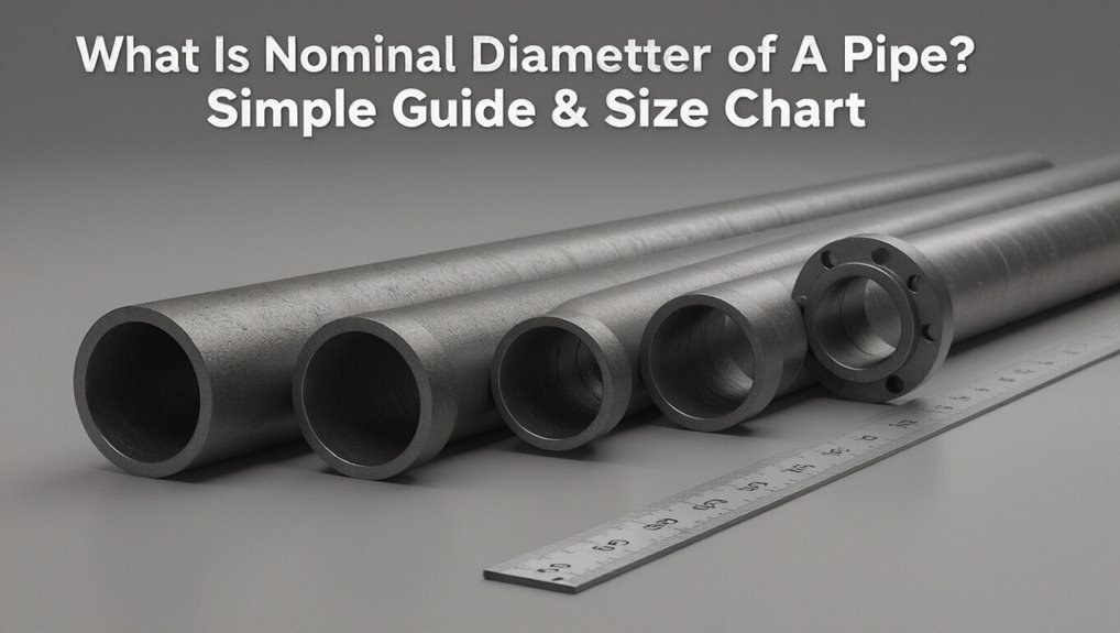
What Is Nominal Diameter of a Pipe? Simple Guide & Size Chart
The nominal diameter of a pipe is a standardized designation used to identify the pipe size for selection and procurement, rather than an exact measurement. It serves as a naming convention (NPS in inches or DN in millimeters) that categorizes pipes by compatible sizes, even though the actual outside and inside diameters can differ due to variations in wall thickness and schedule. Engineers utilize the actual outer and inner diameters for calculations, while the nominal size is primarily for ensuring compatibility and specification. For more details, including charts, conversions, and practical selection tips, continue reading.
Who This Guide Is For and How to Use It
For engineers, technicians, procurement professionals, and students working with piping systems, this guide clarifies the concept of nominal diameter and its practical implications.
It targets readers who select, size, specify, or inspect pipes across sectors—mechanical, civil, chemical, and utilities.
The guide explains when nominal diameter informs compatibility, ordering, and documentation versus when measured dimensions matter.
It outlines expected prior knowledge, useful reference standards, and decision checkpoints: verifying material, wall thickness, and connection type.
Practical tips cover cross-referencing charts, confirming tolerances, and communicating requirements to suppliers.
Appendices list common standards and quick-check procedures for field verification.
Quick Answer: What Is the Nominal Diameter of a Pipe?
The nominal diameter of a pipe is a labeling convention that indicates the pipe’s general size and intended function rather than its exact measured dimension.
It contrasts with actual dimensions—such as outside diameter and bore—which can vary by material and schedule.
Common nominal sizes include 1/2″, 1″, and 2″, each corresponding to specific actual measurements used in practice.
Meaning And Purpose
As a standardized label rather than an exact measurement, nominal diameter identifies a pipe by a convenient round number used for ordering and specification; it conveys general size, mating compatibility, and system design intent without suggesting precise dimensions.
Its purpose is to simplify communication among designers, manufacturers, purchasers, and installers by referencing a common identifier linked to catalogs and standards. Nominal values guide material selection, flow calculations, and equipment interfaces while allowing manufacturers to apply wall thickness, threading, and fittings conventions.
In practice, designers use nominal diameter alongside pressure ratings and material to guarantee functional and interoperable piping systems.
Nominal Vs Actual
Moving from how nominal diameter functions as an ordering and specification shorthand, the distinction between nominal and actual diameter clarifies what that shorthand represents in physical terms.
Nominal diameter is a convenient label tied to historical standards and hydraulic approximations; actual diameter is a measurable physical dimension.
Key contrasts include:
- Nominal: standardized name for selection and compatibility.
- Actual: outside and inside diameters measured in inches or millimeters.
- Wall thickness: determines the difference between nominal and internal diameter.
- Tolerances and manufacturing: cause actual dimensions to vary around specification limits.
Understanding both prevents misfit and guarantees correct flow calculations.
Common Size Examples
Many common nominal pipe sizes are familiar to engineers and tradespeople: for example, a 1-inch nominal pipe (often abbreviated 1″ NPS or 1″ NPT in threaded contexts) typically has an outside diameter of 1.315 inches, while a 2-inch nominal pipe has an outside diameter of 2.375 inches.
Other typical sizes include 1/2″ (OD 0.840″), 3/4″ (OD 1.050″), 3″ (OD 3.500″), and 4″ (OD 4.500″). Wall thicknesses vary by schedule, altering internal diameter.
Manufacturers and standards tables reconcile nominal size, OD, and schedule so installers match fittings, flow capacity, and pressure requirements accurately.
Why Nominal Diameter Exists Instead of Actual Measured Size
Because pipes are produced in a wide range of materials, wall thicknesses, and manufacturing methods, using a fixed “nominal” diameter provides a practical, standardized reference that simplifies specification and interchange even when the actual outside or inside dimensions differ. The nominal system reduces confusion by decoupling identification from measured size, allowing designers, manufacturers, and installers to reference a common label.
Benefits include predictable ordering, compatibility across fittings, and clearer documentation. Typical reasons for adopting nominal sizing:
- Simplifies purchasing and inventory.
- Guarantees compatibility of mating parts.
- Accommodates varying wall thicknesses.
- Facilitates standardization across industries.
DN vs. NPS vs. Nominal Pipe Size: Key Differences
When discussing pipe sizing, DN, NPS, and Nominal Pipe Size are distinct labels that serve different standards and regions: DN (Diamètre Nominal) is a metric designation indicating a rounded nominal diameter in millimeters; NPS (Nominal Pipe Size) is the North American inch-based nominal system that aligns loosely with pipe outside diameters for sizes above 14 in.; and “Nominal Pipe Size” is the general term for the convenient, non-exact label used to identify pipes regardless of actual inside or outside measurements.
DN uses whole millimeters and suits metric specifications; NPS uses inches and couples with schedule-based wall thickness; the generic term bridges conventions.
How Nominal Diameter Is Assigned for Steel and Plastic Pipes
The assignment of nominal diameter differs by material and historical convention.
For steel pipes the number often reflects a legacy NPS/DN system tied to internal dimensions and standard wall thicknesses.
Plastic pipes use sizing that more directly corresponds to outside or inside diameters depending on the standard and application.
Steel Pipe Numbering
Steel pipe numbering assigns a nominal diameter that often differs from the pipe’s actual inside or outside dimensions to simplify specification, ordering, and compatibility across fittings and standards.
Steel sizes follow historical imperial conventions (NPS/nominal pipe size) and metric equivalents, with wall thickness grouped by schedule numbers that affect internal bore.
Marking systems combine nominal size, schedule, and material grade so users can determine pressure and flow characteristics without remeasuring physical parts.
Numbering is standardized by bodies like ASTM and ASME, enabling interchangeability and clear procurement.
- Nominal size label
- Schedule (wall)
- Material grade
- Standard reference
Plastic Pipe Sizing
Moving from steel pipe numbering to plastic piping highlights distinct approaches to nominal diameter assignment driven by material behavior and manufacturing methods.
Plastic pipe sizing uses nominal size tied to inside diameter for some systems (PVC, CPVC) and to a combination of outside diameter plus SDR or CTS conventions for others (PE, PEX).
Manufacturers control extrusion tolerances so OD is consistent while wall thickness varies to meet pressure ratings; SDR expresses that ratio.
Consequently, nominal diameter can represent ID, OD, or a label matching legacy copper sizes, requiring users to consult material-specific standards (ASTM, ISO, AWWA) for correct fittings and flow calculations.
How Wall Thickness (Schedule) Changes Actual Inside Diameter
With increasing wall thickness, the pipe’s inside diameter decreases even though the nominal diameter stays the same. The schedule number denotes wall thickness; higher schedules mean thicker walls and smaller internal bore for the same nominal size. This affects flow area, pressure capacity, and velocity calculations. Material and manufacturing tolerances also influence actual ID.
- Schedule increases → wall thickness increases → ID decreases.
- Same nominal size can have multiple IDs across schedules.
- Hydraulic calculations must use actual ID, not nominal.
- Selection balances pressure rating, required flow, and available fittings for chosen schedule.
How to Read Pipe Markings to Find the Nominal Diameter
After noting that schedule affects the actual inside diameter, the reader can use the stamped or painted markings on a pipe to determine its nominal diameter quickly.
Pipes typically carry a sequence: manufacturer, material, nominal size (in inches or DN), schedule or wall thickness, and heat or batch number.
The nominal size appears as “NPS” or a simple number like 1/2, 1, 2, or as DN followed by metric value (e.g., DN50).
Locate that element and ignore actual measured OD or ID differences caused by schedule.
When markings are worn, consult manufacturer codes or accompanying documentation to confirm the nominal designation.
Field Tips: Measuring a Pipe to Confirm Nominal Diameter Quickly
When confirming a pipe’s nominal diameter on-site, a quick measurement routine focuses on two reliable checks: the outside diameter (OD) and a wall-thickness estimate. The inspector uses simple tools and observable features to infer nominal size without charts.
- Measure OD with calipers or tape across the widest external span; record to nearest 0.5 mm or 1/32″.
- Estimate wall thickness by measuring internal bore with calipers if accessible, or subtract twice measured wall from OD.
- Compare OD and estimated wall to typical nominal ranges remembered or noted.
- Note fittings, threads, and manufacturer marks for final verification.
Standard Nominal Diameter Chart: Nps/Dn With Typical OD and ID Values
The standard nominal diameter chart compares NPS (Nominal Pipe Size) and DN (Diamètre Nominal) side by side to show how imperial and metric designations correspond.
It lists typical outer diameters for each nominal size and provides approximate inner diameters based on common wall thicknesses.
This compact reference helps readers translate between NPS and DN and estimate actual OD and ID for selection and measurement.
NPS vs DN Explained
How do NPS and DN differ and why does it matter for pipe selection?
The article explains that NPS (Nominal Pipe Size) is the North American imperial-based designation, while DN (Diamètre Nominal) is the metric equivalent. Both are nominal labels, not exact measurements; they map to standardized inner and outer dimensions by schedule or series.
Choosing the correct system guarantees compatibility across fittings and international projects.
Key distinctions include:
- Origin: NPS from ANSI/ASME, DN from ISO/EN standards.
- Units: NPS uses inches, DN uses millimeters.
- Interchangeability: Not directly equivalent; tables required.
- Specification: Include both nominal and schedule/series.
Typical Outer Diameters
Several common nominal sizes map to standardized outer diameters (OD) that facilitate compatibility between pipes and fittings across systems.
A typical NPS/DN chart lists nominal sizes (NPS 1/8 to 48, DN 6 to 1200) alongside standardized ODs: for example, NPS 1/8 = 10.3 mm OD, NPS 1/2 = 21.3 mm, NPS 1 = 33.4 mm, NPS 2 = 60.3 mm, NPS 4 = 114.3 mm, and NPS 12 = 323.9 mm.
These ODs remain constant across different wall thicknesses and schedules, enabling consistent coupling, thread engagement, and flange matching regardless of internal bore variations.
Approximate Inner Diameters
Following the standard outer diameters that remain fixed across schedules, approximate inner diameters (IDs) are determined by subtracting twice the wall thickness from the OD and vary with schedule and material. The chart presents representative IDs for common NPS/DN sizes, aiding selection and flow calculations. Users should verify with manufacturer or code tables for precise engineering.
- NPS 1/2 (DN15): OD 21.3 mm, ID range ~12.7–17.0 mm depending on schedule.
- NPS 1 (DN25): OD 33.4 mm, ID range ~21.3–28.6 mm.
- NPS 2 (DN50): OD 60.3 mm, ID range ~47.8–52.3 mm.
- NPS 4 (DN100): OD 114.3 mm, ID range ~101.9–108.5 mm.
Metric DN Chart: Converting DN to Millimeters and Inches
When working with pipe specifications, a Metric DN chart provides the standardized mapping between nominal diameter (DN) values and their corresponding dimensions in millimeters and inches.
The chart lists DN numbers (e.g., DN10, DN25, DN50) alongside nominal bore sizes in millimeters and common inch equivalents, facilitating specification, procurement, and compatibility checks across metric and imperial systems.
It clarifies that DN is a nominal designation rather than an exact physical measurement and helps users select fittings, flanges, and connectors by matching DN to standardized outside or inside dimensions.
Reference to relevant ISO and EN standards guarantees consistent interpretation.
Examples: Translating Nominal Diameter to Actual Dimensions for Schedule 40 and 80
After establishing how DN numbers map to nominal bore sizes in millimeters and inches, concrete examples are useful to show how those nominal designations relate to actual pipe dimensions for common wall thicknesses.
The following examples compare nominal pipe size (NPS), approximate ID, and OD for Schedule 40 and 80 in typical sizes:
- NPS 1/2 — OD 0.840″, ID ≈ 0.622″ (Sch 40) vs ID ≈ 0.546″ (Sch 80).
- NPS 1 — OD 1.315″, ID ≈ 1.049″ (Sch 40) vs ID ≈ 0.936″ (Sch 80).
- NPS 2 — OD 2.375″, ID ≈ 2.067″ (Sch 40) vs ID ≈ 1.939″ (Sch 80).
- NPS 4 — OD 4.500″, ID ≈ 4.026″ (Sch 40) vs ID ≈ 3.826″ (Sch 80).
When Nominal Diameter Is Approximate: Small-Diameter and Large-Diameter Exceptions
In piping standards, the nominal diameter serves as a convenient label rather than a precise measurement, and certain small- and large-diameter pipes deviate noticeably from the nominal-to-actual correspondence used for mid-range sizes.
For small diameters (commonly under 1/2 inch), wall thicknesses and manufacturing tolerances produce actual inside diameters that differ proportionally more from the nominal, so selection must rely on published OD/ID tables.
For very large pipes, standard nominal sizes represent rough categories; actual dimensions vary by industry, material, and fabrication method.
Designers and specifiers consult standards and manufacturer data instead of assuming a simple nominal-to-actual relationship.
How Fittings and Flanges Are Sized Relative to Nominal Diameter
Having noted that nominal diameter can differ from actual pipe dimensions at the extremes, attention turns to how fittings and flanges are specified relative to nominal size.
Manufacturers and standards bodies reference the pipe’s nominal diameter when defining mating dimensions, but key attributes depend on class, schedule, and face type.
Common practices include:
- Matching flange bolt circle and bore to the pipe nominal size and schedule.
- Specifying fittings by nominal diameter with internal geometry adjusted for wall thickness.
- Using adapters when actual OD differs from nominal for transitional joints.
- Referencing standards (ASME, ANSI, ISO) for compatibility and tolerances.
How to Select Pipe by Nominal Diameter for Flow and Pressure Needs
For determining pipe selection by nominal diameter, engineers weigh expected flow rates, allowable pressure drops, and system pressure ratings against the nominal size’s implied internal capacity.
They consult standards and manufacturer tables tying nominal diameter to wall thickness options and pressure classes, ensuring the chosen schedule or SDR meets maximum operating pressure with adequate safety margin.
Compatibility with fittings, valves, and support spacing is checked to preserve system integrity.
Consideration is given to future capacity needs, material corrosion allowances, and installation constraints.
Final selection balances hydraulic requirements, mechanical strength, code compliance, and cost to achieve reliable service.
Calculating Flow Capacity From Nominal Diameter and Internal Area
Using the nominal diameter and the pipe’s internal cross-sectional area, engineers calculate theoretical flow capacity by applying continuity and head-loss relationships to predict volumetric rates under given pressure and velocity conditions.
The process converts ID to area (A = π·d^2/4), estimates mean velocity from Reynolds and friction factors, then uses Bernoulli or Darcy-Weisbach to relate head loss to flow.
Practical capacity adjusts for fittings, roughness, and allowable pressure drop.
Design outputs include flow rate, velocity, and pressure loss for sizing and pump selection.
- Compute area from internal diameter.
- Select target velocity or head.
- Solve for volumetric flow.
- Apply corrections for fittings and roughness.
How Material Choice (PVC, Copper, Steel) Affects ID for the Same Nominal Diameter
Across different piping standards, the same nominal diameter often conceals varying internal diameters because wall thicknesses and manufacturing tolerances differ by material and schedule.
PVC pipes use thinner, uniform walls and often yield larger IDs for a given nominal size compared with metal equivalents; smooth bore and consistent extrusion minimize ID variation.
Copper tubing follows types (K, L, M) with thicker walls reducing ID as type increases; fittings and annealing affect tolerances.
Steel, including black and stainless, follows schedules (40, 80) with heavier walls and greater ID reduction; fabrication tolerances and corrosion allowances further influence usable internal diameter.
Common Mistakes: Using OD vs. ID vs. Nominal Diameter Interchangeably
Many installers and designers mistakenly treat nominal diameter, outside diameter (OD), and inside diameter (ID) as interchangeable, which leads to improper fittings, pressure calculations, and flow estimates. This confusion causes procurement errors, mismatched joints, and safety risks. Clear distinction matters: nominal is a label, OD is external size, ID controls flow and pressure.
- Ordering: buying by nominal without checking OD/ID yields incompatible parts.
- Calculations: using OD instead of ID overestimates flow area and underestimates velocity.
- Fittings: assuming nominal equals physical size causes leaks or stress.
- Inspection: verify actual OD/ID, not just nominal designations.
Standards That Define Nominal Diameter (ASME, ISO, ASTM)
Several international and regional standards organizations—most conspicuously ASME, ISO, and ASTM—establish the definitions, naming conventions, and measurement practices for nominal pipe diameter to guarantee compatibility across materials, applications, and supply chains. These bodies document nominal size series, wall thickness classes, tolerance limits, and labeling rules. Manufacturers, engineers, and inspectors rely on these standards to select, mark, and test piping without ambiguity. Differences in scope and historical practice explain variations in nominal-size usage between regions and industries, but standards provide the authoritative references used in procurement, fabrication, and quality control.
| Standard | Focus |
|---|---|
| ASME | Boiler, pressure, mechanical codes |
| ISO | International dimensional and testing norms |
| ASTM | Material specifications and test methods |
Converting Between Pipe Standards: NPS to DIN/ISO to Metric Piping
When converting between NPS (Nominal Pipe Size), DIN/ISO, and metric pipe systems, attention centers on matching nominal sizes, wall-thickness classes, and the resulting actual inside and outside diameters rather than relying on name equivalence alone.
Practical conversion follows measured dimensions and pressure ratings, using equivalency tables and standardized tolerances.
Key steps include:
- Identify NPS nominal size and schedule or material class.
- Cross-reference DIN/ISO or metric nominal bore and outer diameter.
- Compare wall thickness and calculate internal diameter for flow or strength.
- Confirm pressure-temperature ratings and manufacturing tolerances before selection or substitution.
When Nominal Diameter Matters: Compatibility & Procurement
In procurement and installation, nominal diameter determines compatibility more than the nominal label itself: mismatches in outer diameter, wall thickness, or end connections can prevent proper assembly even when nominal sizes appear equivalent.
Buyers must verify actual OD, schedule or wall thickness, and coupling type rather than rely on nominal size alone. Specifications should list tolerances, material grade, and thread or flange standards.
Inspection of supplier datasheets, cross-referencing standards (ASTM, ISO, EN), and ordering by physical dimensions reduces returns and delays.
Project procurement teams should enforce clear acceptance criteria and involve fabricators early to confirm fit and function.
Cheat Sheet: Choose Nominal Diameter by Application
A brief cheat sheet compares typical nominal diameters for common uses to streamline selection.
For residential water supply, smaller diameters prioritize adequate flow with ease of installation and cost control.
For industrial process lines, larger and application-specific diameters accommodate higher flow rates, pressure requirements, and material compatibility.
Residential Water Supply
For residential water supply, nominal pipe diameter is selected to balance fixture demand, pressure loss, and installation cost; typical choices range from 1/2″ for individual fixtures to 1″–1¼” for whole-house mains, with larger diameters used for multi-family or irrigation service.
Sizing considers peak simultaneous demand, supply pressure, and run length.
Materials (copper, PEX, CPVC) affect allowable flows.
Proper sizing reduces noise, pressure drop, and costs while meeting code.
- 1/2″ — sinks, toilets, individual fixtures.
- 3/4″ — short branch lines, small bathrooms.
- 1″ — main distribution in typical homes.
- 1¼”+ — larger homes, multiple meters.
Industrial Process Lines
When sizing industrial process lines, engineers prioritize flow rate, fluid properties, pressure drop, and process control requirements to select a nominal diameter that guarantees reliable operation and minimizes total cost. Selection balances throughput, allowable velocity, erosion/corrosion risk, and pump/compressor capacity.
Viscous or multiphase streams demand larger diameters to limit pressure loss; high-temperature or cryogenic services require materials and clearances affecting internal diameter. Control valves, meters, and safety devices impose upstream/downstream piping needs.
Redundancy and maintenance access often lead to parallel lines or bypasses. Final sizing integrates hydraulic calculations, economic optimization, and compliance with industry codes and process safety standards.
Quick Reference: Common Nominal Diameter Ranges and Where They’re Used
In many practical settings, nominal pipe diameters are grouped into standard ranges that indicate typical applications and flow capacities. The following quick reference summarizes common ranges and typical uses.
- 1/8″–1/2″: instrumentation, small service lines, low flow and pressure testing.
- 3/4″–2″: residential plumbing, HVAC coils, water supply, moderate flow systems.
- 2½”–6″: commercial plumbing, fire protection mains, medium process lines with higher flow.
- 8″–24″+: municipal mains, large HVAC distribution, major process and bulk transfer pipelines.
These ranges guide selection but final sizing requires hydraulic calculations and code compliance.
Conclusion
Like a row of labeled trunks on a busy dock, the nominal diameter guides hands and orders without revealing every inner curve. It steadies choices, links standards, and keeps fittings aligned across distant workshops. When engineers and buyers consult its shorthand, they navigate complexity with the quiet certainty of a lighthouse: not showing every stone, but giving direction so pipes, projects, and people fit together and flow as designed.