What Does DN Mean in Pipe Size? Simple Guide for DIY & Pros
DN stands for “diamètre nominal” (nominal diameter), which is a standardized size label used to identify pipes, fittings, valves, and flanges. It indicates a nominal internal size class rather than the precise bore or thread type. To ensure compatibility, it’s important to also consider wall thickness (schedule), material, and standard. Additionally, DN is often paired with a pressure rating (PN) for specifications. Understanding DN can help you quickly match components and also relates to imperial NPS, actual diameters, and performance considerations.
What Search Intent Does This Guide Satisfy?
What does a reader expect to find in a guide titled “DN in Pipe Size Explained”? The piece serves users seeking clear, practical information about DN (diamètre nominal) relevance to pipe selection, compatibility, and standards. It targets DIYers needing measurement basics and professionals requiring quick reference on sizing conventions, conversions, and application contexts.
The intent is informational and transactional: educate readers to make correct purchasing or design choices. Content emphasizes concise definitions, typical use cases, standard relationships (without deep technical derivations), and pointers to when to consult specifications or professionals, reducing trial-and-error in projects.
Quick Answer : What DN Means (Short Definition + Example)
DN stands for “diamètre nominal” (nominal diameter), a standardized designation that indicates a pipe’s approximate internal size without specifying exact measurements.
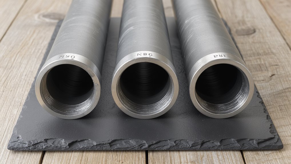
For example, DN50 corresponds roughly to a 2-inch pipe, though actual internal diameters can vary by material and schedule.
The term is used for quick comparison and selection across international piping systems.
DN Definition Overview
A nominal sizing designation used in piping, DN (Diamètre Nominal or Nominal Diameter) indicates a pipe’s approximate internal diameter in millimetres for metric-based systems; for example, DN 50 corresponds to a nominal 50 mm size (actual internal diameter varies with wall thickness and standard).
DN serves as a standardized label across international standards (ISO, EN) to simplify specification, procurement and compatibility.
It does not guarantee precise measurement but provides a common reference for mating fittings and system design.
DN values are integer-based and paired with pressure ratings, material and schedule information to define a complete pipe specification for engineering and installation.
DN Example Comparison
Following the overview of DN as a nominal label, the example comparison clarifies its practical meaning: DN refers to the nominal diameter number (in millimetres) used to match pipes and fittings, so DN 50 indicates a nominal 50 mm size even though the actual internal diameter depends on wall thickness and standard.
A concise example shows DN 50 paired with different schedules or PN ratings producing varying internal diameters and flow capacities.
Practical points include:
- DN 50 with thin wall yields larger ID than thick wall of same DN
- DN 50 vs 2″ nominal (imperial) approximate match
- DN applies to fittings, valves, flanges
- Always check standard (ISO, EN, ANSI)
DN vs NPS and OD: Key Differences
When comparing pipe-sizing systems, engineers distinguish DN (nominal diameter), NPS (Nominal Pipe Size), and OD (outside diameter) by what each dimension represents and how it is measured; DN and NPS are nominal designations tied to internal flow capacity and wall thickness conventions, while OD is the actual outside measurement used for fittings and clearances.
DN uses metric-based nominal numbers correlated to internal diameter ranges, NPS follows imperial conventions where nominal size often differs from true internal or external dimensions, and OD is a precise physical measure.
Compatibility requires consulting standards (ISO, ASME) and matching schedule or wall thickness to guarantee proper fit.
Why DN Matters for DIYers and Pros Alike
For both home projects and commercial installations, DN provides a clear, standardized reference that simplifies material selection and guarantees components work together.
It reduces guesswork, speeds ordering, and lowers mismatch risks between fittings, valves, and pipe sections. Contractors, fabricators, and hobbyists rely on DN for consistent sizing across brands and regions.
Benefits include:
- Easier sourcing of compatible parts without complex conversions
- Clear communication on plans and specifications among teams
- Reduced waste from incorrect purchases or rework
- Streamlined maintenance with readily identifiable replacement sizes
Using DN improves efficiency, accuracy, and cost control in plumbing and piping work.
Common Abbreviations: DN, PN, NPS, BSP, and ISO
Having established why DN streamlines selection and reduces mismatches, attention turns to the common abbreviations encountered in piping: DN, PN, NPS, BSP, and ISO. Each denotes a different sizing or rating system: DN (nominal diameter), PN (pressure rating), NPS (American nominal pipe size), BSP (British Standard Pipe threads), and ISO (international standards). Understanding which applies prevents incompatible fittings and pressure issues. Quick reference:
| Abbreviation | Meaning | Use |
|---|---|---|
| DN | Nominal Diameter | Metric sizing |
| PN | Pressure Number | Rating in bar |
| NPS/BSP | Thread/Size types | Regional fittings |
How ISO and EN Define DN
The section outlines DN as a nominal designation used to classify pipe sizes by a rounded number rather than actual measurements.
It explains how ISO and EN set standardized rules for assigning DN values, tolerances, and correspondence tables to guarantee interchangeability across fittings and systems.
It also clarifies that DN indicates a nominal size and may not match the true internal or external diameter of a pipe.
DN Definition And Purpose
What does “DN” signify in pipe sizing and why is it used? DN, short for “diamètre nominal” or “nominal diameter,” is a standardized label indicating a pipe’s approximate bore for compatibility across fittings and systems. It provides a consistent reference independent of actual measured dimensions.
- Indicates nominal internal size for selection and matching
- Aligns component interfaces (flanges, valves, couplings) across manufacturers
- Serves as a common language in ISO and EN technical documents
- Facilitates design, procurement, and maintenance by reducing ambiguity
DN is descriptive rather than exact, simplifying system interoperability without replacing detailed dimensions.
ISO/EN Standardization Rules
In ISO and EN documents, DN is defined as a nominal designation rather than a measured dimension, with specific rules that govern its application to pipes, fittings, and flanges to guarantee interchangeability across manufacturers and systems.
The standards specify numbering, permissible DN values, and reference tables linking DN to nominal pipe sizes, material groups, and pressure-temperature ratings.
Tolerances, marking conventions, and documentation requirements are included to assure compatibility.
Manufacturers must follow these clauses when producing or certifying components.
Conformance is demonstrated via test reports, certificates, and marked products, enabling designers and installers to select components without verifying exact physical diameters.
DN Versus Actual Diameter
How does DN relate to the pipe’s measured diameter under ISO and EN rules? The standards treat DN as a nominal designation, not a literal measurement. It identifies a standardized size group; actual internal or external diameters depend on wall thickness, material, and series. Designers and plumbers must consult tables converting DN to actual dimensions for specific systems.
- DN is nominal; it conveys classification, not exact millimeters.
- ISO/EN provide conversion tables linking DN to standard OD/ID for materials.
- Wall thickness (schedule/series) alters internal diameter for a given DN.
- Compatibility requires referencing the exact standard and material specification.
How DN Relates to Pipe Schedule and Wall Thickness
When specifying a pipe, nominal diameter (DN) indicates a rounded internal size class while schedule and wall thickness determine the actual internal and external dimensions and pressure capacity; consequently DN alone does not define a pipe’s wall thickness or structural strength.
Pipe schedule (e.g., SCH 40, SCH 80) pairs with DN to set wall thickness for a given material and standard. Higher schedule numbers mean thicker walls and higher pressure ratings for the same DN.
Manufacturers publish tables mapping DN, schedule, wall thickness, and outside diameter. Selecting correct combinations guarantees compatibility, strength, and safe operating pressure for the designated fluid service.
DN Versus Actual Internal Diameter: What Changes With Wall Thickness?
With a constant DN, the internal diameter of a pipe decreases as wall thickness increases, because DN denotes a nominal size class rather than the actual bore; consequently two pipes with the same DN but different schedules can have noticeably different clearances, flow areas, and pressure-drop characteristics.
The following points summarize practical effects of wall thickness on nominal pipes:
- Reduced internal diameter lowers volumetric flow and increases velocity for a given flow rate.
- Thicker walls improve pressure rating but reduce hydraulic capacity.
- Fittings and valves sized by DN may not match true bore dimensions.
- Accurate system design requires checking actual ID, not DN alone.
How to Read a Pipe Label That Includes DN and PN
Interpret a pipe label that lists DN and PN as a compact summary of its nominal size and pressure rating: DN denotes the nominal diameter class used for matching fittings and pipes, while PN specifies the maximum allowable working pressure in bar at a reference temperature.
Read the rest of the marking for material grade, standard (e.g., ISO, EN), and manufacturing code.
DN is followed by a number (e.g., DN50); PN appears as PN10, PN16, etc.
Confirm temperature limits tied to PN in accompanying documentation.
Use both DN and PN when selecting flanges, valves, and supports to make sure mechanical and pressure compatibility.
Converting DN to Metric and Imperial Sizes (Simple Chart Logic)
Starting from the DN number, conversion to metric and imperial sizes follows a simple lookup logic: DN indicates a nominal bore in millimeters (roughly the internal diameter class), which is matched to the nearest standard metric pipe O.D. or wall size and then converted to the closest common imperial (inch) nominal pipe size.
- Identify the DN value (nominal bore class) and reference a standard metric table.
- Match DN to the standard metric outside diameter and typical wall thickness for that series.
- Use the metric O.D. to find the nearest imperial nominal pipe size or tubing equivalent.
- Note that fittings and standards (ISO, DIN, ASTM) affect exact compatibility.
Three Quick DN-to-Inch Conversions Homeowners Can Use Now (15mm, 25mm, 50mm)
Homeowners frequently need quick DN-to-inch references when replacing fittings or checking pipe sizes; three common DN values—DN15, DN25, and DN50—correspond roughly to ½”, 1″, and 2″ nominal imperial sizes respectively, though exact matches depend on whether the pipe is measured by nominal bore, actual outside diameter, or tubing standards.
DN15 typically matches 15mm tubing used for sinks and small appliances.
DN25 aligns with 25mm domestic lines for showers and some hot-water runs.
DN50 is comparable to 2″ drains and larger supply feeders.
Use supplier specs or measured diameters when selecting adapters or replacement parts.
How DN Relates to Pipe Schedule and Wall Thickness (Practical Notes)
The relationship between DN and pipe schedule is clarified by recognizing that DN denotes nominal bore while schedule indicates wall thickness and pressure capacity.
A given DN can correspond to multiple schedules, so outer diameter may remain constant while internal flow area changes with wall thickness.
Practical selection consequently requires checking schedule specifications, not relying on DN alone.
DN Versus Schedule
How does DN (diamètre nominal) correspond to pipe schedule and wall thickness in practical terms? DN labels an approximate internal diameter; schedule numbers specify wall thickness for a given nominal pipe size. They interact: the same DN can have multiple schedules, altering strength and flow. For practical selection, consider these points:
- DN indicates size class, not exact bore.
- Schedule defines wall thickness and pressure capability.
- Converting DN to NPS clarifies which schedule options apply.
- Inspect manufacturer tables to match DN + schedule to actual OD, ID, and pressure rating.
Choose DN then select schedule based on required pressure and application.
Wall Thickness Impact
In practical piping selection, wall thickness—expressed by schedule—directly alters a DN-classified pipe’s internal diameter, structural strength, and allowable pressure, so engineers must treat DN as a size category and schedule as the determinative specification for performance.
Wall thickness reduces bore for a given DN, affecting flow, velocity, and head loss.
It increases burst and collapse resistance and influences thermal expansion and assembly methods.
Material, manufacturing tolerance, and corrosion allowance determine required schedule for service conditions.
When specifying, combine DN with the appropriate schedule or explicit wall dimension to guarantee hydraulic capacity, mechanical safety, and compliance with codes.
Choose DN for Water Supply Lines
When selecting a DN for water supply lines, designers balance flow capacity, pressure drop, and pipe availability to meet demand without oversizing; appropriate DN guarantees sufficient peak flow while minimizing cost and maintaining acceptable velocity and head loss.
The process assesses fixture units, peak simultaneous demand, and required service pressure. Material selection affects internal roughness and thus hydraulic performance; standard DN sizes simplify fittings and procurement.
Future-proofing considers potential demand increases and maintenance access. Practical selection follows codes and manufacturer charts to match velocity (typically 0.6–2 m/s) and head loss limits, avoiding excessive noise or erosion.
- Calculate peak flow from fixture units
- Check velocity and head loss
- Compare material roughness and available DN
- Verify code and manufacturer charts
Choose DN for Drainage and Sewer Systems
Selecting DN for drainage and sewer systems requires different priorities than water supply lines, emphasizing solids passage, self-cleansing velocity, and prevention of blockages over peak delivery capacity.
Designers select DN to provide sufficient hydraulic radius and flow depth for solid transport, often using larger DN than equivalent water mains. Slope, expected sewage composition, and upstream fixture counts inform DN choice to maintain self-cleansing speeds at low flows.
Service continuity, access for rodding and inspection, and alignment with local codes determine practical DN sizes. Material strength and jointing matter but are secondary to maintaining unobstructed flow and ease of maintenance.
Choose DN for Gas Piping and Safety Considerations
Why does DN selection for gas piping demand different priorities than for water or sewer lines? Gas systems focus on flow, pressure drop, leak prevention and regulatory compliance. Proper DN guarantees safe delivery while minimizing risk.
- Calculate DN from required flow rate and maximum allowable pressure drop.
- Use materials and joint types rated for gas; larger DN can reduce velocity and leakage risk.
- Follow local codes, inspection schedules and ventilation requirements tied to DN choices.
- Include safety margins, considerations for future demand, and certified installation to prevent combustible accumulation.
DN decisions for gas prioritize safety and compliance over purely hydraulic concerns.
Choose DN for HVAC and Chilled-Water Systems
For HVAC and chilled-water systems, DN selection centers on balancing flow capacity, pressure drop, and velocity to maintain thermal performance and avoid noise, erosion, or pump inefficiency. Engineers prioritize compatibility with system components, temperature limits, and pump curves while allowing future expansion and minimizing fittings that increase head loss. Material selection and insulation impact thermal losses; corrosion allowance affects long-term diameters. Standard DN sizes simplify procurement and balancing. Coordination with control valves and strainer sizes assures serviceability. Thermal-hydraulic modeling validates choices before installation to prevent costly resizing.
| Consideration | Impact |
|---|---|
| Component match | Reliability |
| Pressure drop | Energy use |
| Noise/erosion | Longevity |
| Standard sizes | Supply ease |
| Serviceability | Maintenance |
How Flow Rate and Velocity Guide Your DN Choice
When matching DN to a system’s hydraulic needs, flow rate and fluid velocity act as the primary determinants, because they directly set the required cross-sectional area and influence pressure drop, noise, and erosion risk; consequently engineers calculate the expected volumetric flow and then select the smallest DN that keeps velocity within acceptable limits for the fluid type and application while minimizing head loss and cavitation potential.
Designers compare target velocities to recommended ranges, consider peak versus average flows, and account for future demand. Key considerations include:
- Maintain velocity to limit erosion and noise.
- Avoid excessive velocity that increases pumping energy.
- Size for peak flow events.
- Consider fluid abrasiveness and temperature.
Using Darcy–Weisbach and Hazen–Williams Basics for DN Decisions
The selection of DN should account for how flow rate affects velocity and consequently energy losses along the pipeline. Engineers weigh the choice of friction factor—whether from Darcy–Weisbach formulations or Hazen–Williams empirical coefficients—because it directly alters computed head loss.
Accurate pressure loss calculations using the chosen method inform whether a given DN meets system performance and pump requirements.
Flow Rate Impact
Understanding how flow rate influences DN selection requires linking hydraulic losses to pipe diameter through simple formulas like Darcy–Weisbach and Hazen–Williams.
The designer assesses required flow rate, acceptable head loss, and selects DN to balance velocity and pressure drop. Higher flow demands larger DN to reduce frictional loss; smaller DN increases velocity and energy cost. Practical checks safeguard velocities remain within recommended ranges for the fluid and system.
- Higher Q raises head loss ∝ Q^2 in Darcy–Weisbach for turbulent flow.
- Hazen–Williams links Q and diameter with empirical coefficients.
- DN choice trades material cost versus pumping energy.
- Verify service-specific velocity limits.
Friction Factor Choice
Selects an appropriate friction factor by comparing Darcy–Weisbach and Hazen–Williams frameworks, because the chosen method controls how diameter, flow, and head loss interrelate.
The Darcy–Weisbach approach uses a dimensionless friction factor dependent on Reynolds number and relative roughness, suitable for varied fluids and temperatures and for turbulent or laminar regimes.
Hazen–Williams gives a single empirical coefficient aimed at water under turbulent flow, simplifying calculations but limiting applicability.
For DN selection, Darcy–Weisbach supports precise-sizing across materials and velocities; Hazen–Williams offers quick estimates for typical water distribution.
Choice balances accuracy needs, fluid conditions, and available roughness data.
Pressure Loss Calculation
Calculate pressure loss using either the Darcy–Weisbach or Hazen–Williams formulation to inform DN decisions by relating flow rate, pipe diameter, roughness, length, and head loss.
The chosen equation yields head loss per length, enabling comparison between DN sizes for required flow and allowable pressure drop. Darcy–Weisbach suits varied fluids and Reynolds numbers; Hazen–Williams gives simpler water-only estimates.
Analysts should convert DN to internal diameter and select roughness or C-values consistent with material and age before computing.
- Use Darcy–Weisbach for precision and non-Newtonian or variable conditions.
- Use Hazen–Williams for quick water estimates.
- Compare head loss per meter across DN options.
- Include fittings as equivalent lengths.
Why DN Changes Pump Sizing and Energy Use
When pipe nominal diameter (DN) changes, the resulting shifts in flow velocity, frictional losses and hydraulic head alter both pump selection and operating energy, so engineers must reassess pump curves and system head curves to match performance.
A smaller DN raises velocity and friction factor, increasing head loss and required pump power; a larger DN lowers losses but may reduce velocity below efficient pump operating ranges and raise capital cost.
Changes affect NPSH, cavitation risk, and pump duty point relative to best efficiency point.
Accurate recalculation of system head versus flow guarantees correct impeller sizing, motor selection, and realistic energy consumption estimates.
Matching Fittings and Flanges to a Pipe’s DN
In matching fittings and flanges to a pipe’s DN, compatibility rests on more than the nominal diameter alone: thread type, flange drilling pattern, pressure class, and wall thickness (schedule) must align to guarantee a leak-free, mechanically sound connection.
The installer or designer verifies DN against mating component standards, material compatibility, and gasket type to prevent misfit or corrosion.
Key checks include:
- Confirm flange face type and bolt circle match DN-based standard.
- Verify pressure rating (PN/class) equals or exceeds system requirements.
- Match wall thickness/schedule so internal diameter and strength are consistent.
- Make certain material and gasket selection suit the service fluid.
DN and Threaded Connections: Thread Standard Compatibility
How do nominal DN sizes relate to threaded connections across different standards? DN denotes pipe bore, not thread form; compatibility requires matching DN to the thread standard (BSP, NPT, ISO, JIS) and the corresponding nominal pipe size. Threads with the same DN can differ in pitch, angle, and taper. Consequently, fittings must be specified by both DN and thread type.
Adapters or conversion fittings may bridge standards but can introduce leak or strength concerns. For reliable joints, confirm DN, external vs internal thread designation, sealing method (tapered vs parallel), and applicable standard to make certain mechanical and hydraulic compatibility.
Welds and Flanges: Which DN Dimensions to Confirm
After confirming DN and thread standard for a connection, attention shifts to welds and flanges where a slightly different set of DN-related dimensions govern fit and performance.
The installer must verify flange face type, bolt circle diameter, number and size of bolt holes, and pipe end preparation relative to the DN designation. Matching DN alone can mislead if flange standards (PN/ANSI) differ. Confirming these dimensions prevents leaks, misalignment, and wasted fabrications.
Typical checklist items include:
- flange face (RF, FF, RTJ) compatibility
- bolt circle and hole pattern
- weld end type (butt, socket) and prep
- ring gasket dimensions matching DN
When DN Alone Is Not Enough: Material and Temperature Limits
Considering material selection and temperature ratings alongside DN prevents specifying a pipe that fits dimensionally but fails in service. DN indicates nominal diameter but not pressure, creep, thermal expansion, or chemical compatibility. Engineers must pair DN with material temperature limits and applicable pressure ratings to guarantee safe operation.
| Property | Impact | Action |
|---|---|---|
| Temperature limit | Affects strength | Choose compatible material |
| Pressure rating | Varies with temp | Use derating factors |
| Chemical exposure | Causes degradation | Select resistant lining |
| Thermal expansion | Alters clearances | Provide expansion joints |
Documenting these factors avoids mismatched selections and premature failures.
How Pipe Material (PVC, Copper, Steel) Changes Effective DN Use
Material choice governs how nominal diameter (DN) translates into real-world performance: PVC, copper, and steel each bring different wall thickness standards, pressure-temperature behavior, joint types, and allowable fittings that alter flow capacity and installation clearances.
The effective DN depends on actual internal diameter after wall thickness and fittings are considered.
Designers select material based on expected pressure, temperature, compatibility, and mechanical demands; this affects required DN to achieve target flow.
- PVC: thicker walls reduce internal diameter; solvent-weld or gasketed joints limit temperature.
- Copper: consistent bore, soldered or compression joints.
- Steel: thinner bore variation, threaded or welded joints.
- Fittings: vary across materials, changing effective flow.
Corrosion, Scaling, and DN: Long-Term Flow Impacts
Frequently, corrosion and mineral scaling progressively reduce a pipe’s effective DN by narrowing the internal bore, increasing hydraulic resistance and lowering flow capacity over time.
Metal pipes develop pitting and uniform corrosion; deposits adhere and roughen surfaces.
Scale from hard water forms layers that progressively decrease cross-sectional area.
Reduced DN raises head loss, lowers velocity for given pressure, and can shift systems outside intended operating ranges.
Effects depend on water chemistry, flow regime, temperature, and material.
Long-term impacts include higher pump energy, reduced delivery, and increased maintenance.
Mitigation involves material selection, water treatment, and periodic descaling to preserve nominal DN and performance.
Measuring an Unknown Pipe’s DN On Site : Step-By-Step
The technician first measures the pipe’s outside diameter with calipers or a tape.
Wall thickness is then determined by a micrometer or ultrasonic gauge to calculate the internal diameter.
The measured dimensions are finally matched to a DN conversion chart to identify the nominal diameter.
Measure Outside Diameter
When measuring an unknown pipe’s DN on site by its outside diameter, technicians should start by ensuring the pipe is clean and free of coatings or buildup that could skew the measurement; accurate OD is the foundation for mapping to the correct DN.
Using calipers or a tape, measure the maximum external span across the pipe. Repeat at several points to confirm roundness. Record measurements in millimeters. Compare the averaged OD to a DN conversion chart to infer nominal size, noting material and standards for final verification.
- Use vernier or digital calipers for precision
- Measure perpendicular to axis
- Take three readings and average
- Note any dents or irregularities
Determine Wall Thickness
Measure wall thickness using instruments and methods suited to the pipe material and site conditions, since accurate thickness is essential for selecting the correct DN and verifying pressure ratings.
Use calipers on exposed ends where possible; measure inside and outside diameters and compute thickness as half the difference.
Where ends are inaccessible, employ ultrasonic thickness gauges, following manufacturer calibration and coupling procedures for the material.
For thin-walled or lined pipes, take multiple readings around circumference and along length to detect variance.
Record units and measurement points.
Note corrosion, deposits, or coatings and adjust interpreted true metal thickness accordingly for DN assessment.
Match To DN Chart
With accurate outside and inside diameters and confirmed wall thickness in hand, the next step is to match those measurements to a DN chart to identify the nominal pipe size.
The technician locates the chart for the applicable standard (ISO, EN, or manufacturer), then compares measured OD and wall to charted OD/ID and schedule equivalents to find the closest DN.
If values fall between entries, select the best functional match or re-measure.
Record supporting data and photo evidence for verification.
- Verify chart standard matches pipe origin.
- Use OD first, then confirm with ID.
- Note measurement tolerances.
- Mark selected DN on-site.
Tools to Measure and Verify Pipe DN Accurately
Accurately determining a pipe’s nominal diameter (DN) relies on a set of precise, purpose-built tools that address external, internal, and profile measurements. A caliper measures outer diameter; inside calipers and bore gauges capture ID and wall thickness. Tape measures and ruling gauges suit larger pipes; thread gauges check thread form for fittings tied to DN. Depth gauges verify socket depths. A feeler gauge and profile templates confirm flange and groove specifications. Digital calipers and micrometers improve repeatability and recordkeeping for verification.
| Tool | Purpose |
|---|---|
| Vernier/Digital caliper | External OD, step measurements |
| Inside caliper/bore gauge | Internal diameter |
| Micrometer | Wall thickness, small OD |
| Tape measure/rule | Large pipe OD/length |
| Thread/profile gauges | Thread form, flange/profile verification |
Common Mistakes When Interpreting DN in Mixed-Standard Systems
After tools and methods for verifying DN have been covered, common mistakes emerge when systems combine different standards (metric DN, NPS, BSP, ANSI). Misinterpretation can cause leaks, mismatched fittings, or pressure issues. Key pitfalls include:
- Assuming DN equals outside diameter; threads and wall thickness vary.
- Mixing nominal sizes across standards without conversion tables.
- Relying on stamped markings that omit tolerance or schedule information.
- Ignoring thread form differences (parallel vs tapered) when coupling parts.
Awareness of these specific errors prompts verification through measurement, reference charts, and supplier specs before assembly, reducing retrofit complications and safety risks.
How to Source Replacement Parts by DN for Repairs
When sourcing replacement parts by DN for repairs, technicians should first verify the component’s actual dimensions and thread form rather than relying solely on the nominal DN marking. They should inspect fittings, measure outside and inside diameters, wall thickness, and thread pitch with calipers and gauges.
Cross-reference measured values against standards (ISO, EN) and manufacturer datasheets to identify compatible parts. For valves, flanges, and couplings, confirm pressure rating and material compatibility.
Record the measured DN, actual dimensions, and relevant standard codes. Use these precise data when consulting catalogs or suppliers to avoid mismatches and make certain reliable repairs.
Ordering Pipes: What DN Information Suppliers Expect
When ordering pipes, suppliers expect the DN to be provided as the primary identifier of nominal diameter and compatibility with fittings.
They use the DN to cross-reference standards, wall thicknesses and end connections rather than as an exact physical measurement.
Clear specification of the nominal DN along with material and pressure rating streamlines quotation and fulfillment.
How Suppliers Use DN
Suppliers rely on DN as the primary shorthand to identify a pipe’s nominal bore and pair it with the correct fittings, flanges, and valves during order processing.
Purchase orders, catalogs, and electronic systems list DN alongside material, pressure rating, and standard (e.g., ISO, EN).
Warehouse staff match DN to stocked items and pick compatible components.
Clear DN specification speeds quotes and reduces returns.
- DN plus pressure class directs suitable flange drilling
- DN with material code narrows available stock
- DN used in ERP and inventory labels for tracking
- DN referenced on test certificates and delivery notes
Specifying Nominal Size
Having established how DN is used operationally, the next step is to specify the nominal size precisely on orders so procurement and production teams can fulfill requirements without rework. The purchaser should list DN, corresponding outside diameter, wall class or schedule, material, and tolerance. Suppliers expect DN with units (e.g., DN50) and any project code or standard (EN, ISO, ASME). Clarify whether size is nominal or actual bore. Include finishing, end preparation, and test requirements. Use an order template to avoid ambiguity.
| Field | Example | Required? |
|---|---|---|
| DN | DN50 | Yes |
| OD | 60.3 mm | Yes |
| Class/Std | PN16 / EN | Yes |
Practical Tips for Retrofits When Original DN Isn’t Stamped
In retrofit projects where the original DN is not stamped on pipework, technicians rely on a combination of direct measurement, fitting profiles, and historical documentation to identify the correct nominal diameter. Practical tips prioritize measurement accuracy and component compatibility to avoid mismatches.
Actions include verifying OD and wall thickness, checking mating flanges or threads, and consulting installation drawings or supplier catalogs. When uncertainty persists, trial fittings and pressure checks confirm suitability before permanent joins.
- Measure external diameter and wall thickness with calipers
- Compare thread profiles or flange bolt patterns
- Review original drawings or purchase records
- Use test fittings and leak tests
Regulatory and Local Code Issues Tied to DN
Regulatory requirements for DN can differ markedly between jurisdictions, affecting allowable materials and sizing tolerances.
Local code variations often determine whether a nominal DN designation is acceptable or if metric/imperial conversions must be documented.
Permit and inspection procedures frequently require accurate DN identification on plans and may trigger corrective work if mismatches are found.
Local Code Variations
Across different jurisdictions, DN (diamètre nominal) is interpreted and applied through a patchwork of local codes and standards that can affect allowable pipe materials, sizing tolerances, pressure ratings, and labeling requirements. Local authorities may adopt ISO, EN, or national variants, leading to subtle dimensional or marking differences. Installers and designers must cross-check project specs against municipal rules to guarantee compliance.
Common areas of variation include:
- accepted conversion tables between DN and nominal inch sizes
- mandated testing or certification for specific DN ranges
- permitted materials and pressure class pairings
- labeling and documentation detail required on-site
Permit And Inspection
When tied to DN-based specifications, permits and inspections focus on verifying that selected pipe sizes, materials, and pressure classes match approved plans and local code variations.
Authorities review drawings to confirm DN designations correspond to required flow capacity and service conditions.
Inspectors check labeling, joint methods, and compatibility with fittings, ensuring substitutions are documented and approved.
Testing protocols—pressure tests, leak checks, and material certifications—must be demonstrated per permit conditions.
Noncompliance can trigger corrective orders, fines, or rework.
Contractors are advised to submit clear DN references on permits and maintain records for final sign-off to avoid delays and code disputes.
International Projects: Handling DN Differences Across Countries
In international projects, differences in nominal diameter (DN) standards require careful coordination of specifications, fittings, and documentation to prevent mismatches at procurement and installation.
The project team should map DN to local standards, specify tolerances, and list approved suppliers to avoid surprises.
Clear drawing notes and cross-reference tables reduce interpretation errors.
Contracts must state which standard governs.
- Verify equivalent pipe dimensions (OD, wall) and pressure ratings
- Use adapters or junction fittings where standards differ
- Require manufacturer data sheets and traceable certificates
- Train installers on local marking and testing conventions
Quick Troubleshooting: Low Flow or High Pressure Despite Correct DN
When flow is below expectations or pressure is unusually high despite correct DN, common culprits include valve orientation, unexpected restrictions, and regulator settings.
Inspecting check valve direction first can quickly reveal reverse or partially closed valves.
Mapping restriction locations and verifying pressure regulators completes a focused troubleshooting sequence.
Check Valve Orientation
Facing unexpected low flow or high pressure despite a correctly sized DN, the orientation of a check valve is a common and often overlooked cause. A misinstalled check valve can restrict flow, cause pressure spikes, or chatter.
Inspection and correction are straightforward: verify flow direction arrow, make certain valve sits level if required, and confirm spring or flap moves freely. Common signs include intermittent flow, noise, and upstream pressure buildup.
Quick steps:
- Confirm arrow aligns with planned flow direction.
- Remove and cycle the valve to check for sticking.
- Reinstall with correct support and alignment.
- Replace if internal damage or corrosion is found.
Pipe Restriction Locations
Across a piping system, restrictions can occur at predictable points—entrances, fittings, valves, and abrupt diameter changes—that produce localized pressure drops or flow constriction even when DN is correct. The author notes common trouble spots: partially closed or damaged valves, internal debris at entry points, narrowed fittings or adapters, weld beads and burrs, and misaligned joints creating turbulence. Long runs with many elbows or sudden expansions/contractions amplify losses.
Inspect visually and with pressure/flow measurements upstream and downstream of suspected points. Simple fixes include clearing debris, replacing restrictive fittings, reorienting or restoring valves, and smoothing transitions to restore expected flow.
Pressure Regulator Settings
Problems at fittings and valves often mimic issues caused by improper pressure regulator settings, so the next check should be the regulator itself.
The technician inspects setpoint, gauge accuracy, and downstream pressure under load. Incorrect setpoints can cause low flow or excessive pressure even when DN sizing is correct. Verify bleed ports, diaphragms, and spring condition; listen for chattering. If adjustments are needed, change incrementally and recheck system response.
- Confirm regulator setpoint matches system design
- Compare static and dynamic pressures with a calibrated gauge
- Inspect for wear, debris, or stuck valve components
- Replace or recalibrate if drift or damage is found
Checklist: Confirm These DN Details Before Buying or Installing
Before purchasing or installing pipe, confirm the nominal diameter (DN) matches system requirements, noting that DN denotes inner size for metric fittings but can correspond differently to imperial measurements; verify the exact DN value, the matching outside diameter for mating components, and any applicable tolerance or class so fittings, valves, and flanges will assemble correctly. Check material compatibility, wall thickness (PN or schedule), connection type (welded, threaded, flanged), and measurement units. Inspect markings, manufacturer certificates, and spare part DN equivalence lists. Coordinate on-site measurements with purchased items before assembly to prevent mismatches.
| Item | Verify | Action |
|---|---|---|
| DN value | Exact number | Match drawings |
| OD | Mating parts | Measure/sample |
| Tolerance/class | PN/Schedule | Confirm spec |
| Connection | Type, face | Inspect fittings |
Further Standards and Resources on DN
In consulting industry guidance and standards, professionals should reference internationally recognized specifications—such as ISO 6708 for nominal diameters, ISO 2531/EN 545 for ductile iron pipes, EN 1092 for flanges, and ASME B36.10/B36.19 for steel pipe dimensions—to make certain DN designations, outside diameters, and pressure classes align across components and regions.
Independent verification against national codes (e.g., BS, DIN, ASTM) and manufacturer datasheets reduces mismatch risk. Useful resources include standards bodies, technical handbooks, and online conversion tables.
Practical steps:
- Consult applicable ISO/EN/ASME standards before selection
- Use manufacturer dimension sheets for fittings
- Cross-check pressure/temperature ratings
- Archive referenced standard versions
Conclusion
To summarize, DN (diamètre nominal) standardizes nominal pipe sizes across regions, helping DIYers and professionals match fittings and calculate flow. An interesting statistic: over 60% of international plumbing failures reported in a 2019 industry survey were linked to mismatched sizing or fitting standards, underscoring the practical importance of understanding DN versus NPS/OD. Paying attention to DN, PN, thread type and unit conversions reduces leaks, downtime and costly rework on cross-border or multi-standard projects.