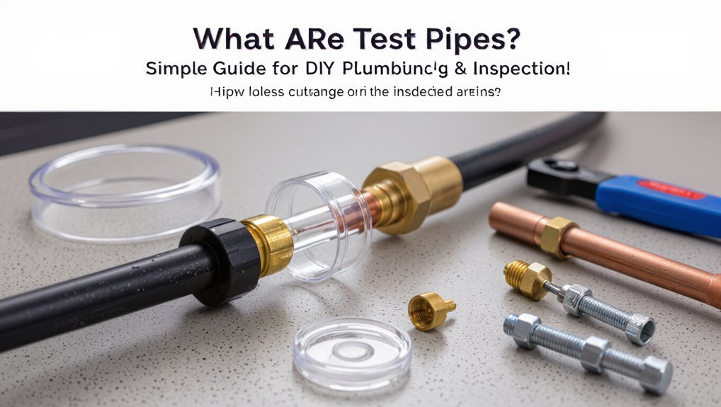
What Are Test Pipes? Simple Guide for DIY Plumbing & Inspection
A plumbing test pipe is a temporary fitting designed to isolate a section of a water or drain system for testing purposes. It allows you to pressurize, drain, or fill that section to check for leaks, pressure integrity, or flow issues. Test pipes connect to existing lines using caps, valves, or adapters, and they incorporate gauges and plugs for monitoring results without altering the permanent plumbing. They are made from materials that match your system—such as PVC, copper, PEX, or ABS—and following straightforward procedures minimizes risks. The guide further details how to select, install, and troubleshoot test pipes effectively.
What Is a Plumbing Test Pipe?
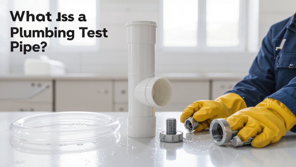
In plumbing, a test pipe is a temporary fitting used to isolate and assess sections of a system for leaks, pressure integrity, or flow performance. It connects to existing lines, allowing controlled pressurization or fill-and-observe procedures without altering permanent components.
Test pipes come in various materials and connectors to match pipe types and diameters, and they often include valves, gauges, or plugs for monitoring. Installation is straightforward for competent DIYers or technicians, and removal leaves the system unchanged.
The device simplifies diagnostics by localizing faults and validating repairs, reducing time and risk compared with full-system disassembly.
When and Why You Need a Test Pipe
Because routine inspections, repairs, and new installations each present unique risks to system integrity, a test pipe becomes essential whenever a segment of plumbing must be isolated and evaluated without disrupting the rest of the network.
It is needed when verifying pressure tightness after soldering or sealing, confirming drainage and vent performance, or diagnosing leaks confined to a branch.
Test pipes prevent contamination during potable water checks and allow localized pressure or smoke testing.
They are used before backfilling trenches, commissioning new fixtures, or troubleshooting intermittent faults, reducing risk, saving time, and avoiding unnecessary system-wide shutdowns or invasive dismantling.
How Inspectors and DIYers Use Test Pipes
Inspectors and DIYers rely on test pipes to conduct pressure testing procedures that verify system integrity under standardized conditions.
They use controlled pressurization and gauges to observe pressure hold times and identify anomalies.
When pressure loss is detected, visual inspection, soap solution, and electronic leak location techniques are employed to pinpoint failure points.
Pressure Testing Procedures
Pressure testing procedures establish systematic steps for applying, monitoring, and documenting pressure in test pipes to verify system integrity and detect leaks. Inspectors and DIYers isolate sections, pressurize with air or water to specified targets, hold for a set duration, record readings, and compare against acceptance criteria. Safety protocols and calibrated gauges guarantee reliable data. Clear records note initial pressure, stabilization, hold time, final pressure, and observations. Visual checks complement measurements. Typical checklist elements:
| Step | Detail |
|---|---|
| Isolation | Valves closed, vents opened |
| Pressurize | Target psi or kPa |
| Hold | Specified minutes |
| Record | Start/end readings, notes |
Leak Location Techniques
Locate leaks in test pipes by combining systematic isolation with visual, auditory, and measurable detection methods.
Inspectors segment systems, cap sections, and pressurize to narrow leak zones. Visual checks target wet spots, corrosion, and escaping bubbles when soapy solution is applied.
Auditory detection uses listening sticks or sensitive microphones to hear hissing in concealed areas.
Measurable techniques include pressure decay readings, dye tracing for low-flow breaches, and smoke or gas tests for otherwise inaccessible joints. Thermal imaging reveals temperature differentials from escaping fluid.
Findings are documented, photographed, and marked; repairs are prioritized by severity, accessibility, and potential water damage.
Test Pipe Types and Common Fittings
Test pipes come in several materials and configurations—copper, CPVC, PEX, and threaded steel being the most common—each chosen for specific test media, temperature ranges, and connection methods.
Common types include straight sections, coils for thermal expansion simulation, and insulated runs for hot-water testing.
Typical fittings are unions, couplings, tees, elbows, and adapters enabling pressure isolation, directional changes, and instrumentation connections.
Quick-connects and compression fittings allow temporary assemblies; threaded and soldered joints suit permanent rigs.
Valves such as ball, gate, and needle control flow and pressure application.
Proper selection guarantees leak-free testing and accurate diagnostics.
Test Pipe Materials: PVC, ABS, Copper
The section compares common test pipe materials, highlighting PVC’s cost-effectiveness, ease of handling, and chemical resistance.
It then contrasts copper’s durability and heat tolerance with ABS’s impact strength and suitability for low-temperature applications.
The goal is to clarify material trade-offs for selection of appropriate test piping.
PVC Test Pipe Benefits
Many installers prefer PVC test pipe for its combination of low cost, chemical resistance, and ease of handling.
PVC offers lightweight durability, simplified cutting and solvent-weld joining, and consistent sizing that speeds assembly during pressure or leak tests.
Its resistance to common household chemicals and corrosion reduces contamination risk and extends service life in temporary setups.
PVC is widely available in multiple diameters and pressure ratings, making selection straightforward.
For DIY testing, its affordability and predictable performance balance safety and practicality.
Limitations include temperature sensitivity and incompatibility with some solvents, which should guide appropriate application choices.
Copper Versus ABS
Although copper and ABS each serve as durable options for temporary and permanent piping, they differ markedly in cost, installation methods, and performance characteristics that influence selection for testing or long-term use.
Copper offers excellent heat resistance, longevity, and corrosion tolerance in many environments; it soldered or pressed fittings require skill and tools, raising labor costs.
ABS is lightweight, inexpensive, and easy to assemble with solvent cement or mechanical joints, making it attractive for quick tests and drains; it lacks copper’s heat tolerance and can degrade with prolonged UV exposure.
Choice hinges on budget, ambient conditions, and expected service life.
Choosing the Right Test Pipe Size
Selecting the correct test pipe size requires matching the pipe’s internal diameter to the system’s flow characteristics, pressure range, and the testing method to guarantee accurate results and safe operation. The writer notes that sizing follows fixture unit equivalents, expected maximum flow, and allowable pressure drop; oversizing hides leaks, undersizing raises velocity and noise. Industry charts and manufacturer specs guide selection; local codes set minimums. Consider temporary versus permanent installations and material compatibility. Proper sizing simplifies isolation and reduces false positives during testing.
| Criterion | Guidance |
|---|---|
| Flow rate | Match peak demand |
| Pressure | Stay within rated limits |
Tools You Need for Test-Pipe Work
For efficient and safe test-pipe work, a concise set of hand and measurement tools is essential: pressure gauges and calibrated manometers for accurate test readings; adjustable and pipe wrenches, tubing cutters, and deburring tools for secure fittings and clean joints; durable plugs and test caps rated for the anticipated pressure; leak-detection supplies such as soap solution or electronic sniffers; and appropriate sealants, tapes, and spare gaskets compatible with the pipe material.
Additional useful items include hose assemblies and quick‑connect fittings, a reliable pump or compressor with regulators, inspection mirrors or borescopes, portable lighting, cleanup rags, and a compact toolkit for on-site adjustments.
Safety Checks Before Pressurizing a Test Pipe
Before pressurizing a test pipe, a systematic safety check verifies that the assembly, environment, and personnel controls are all suitable for the planned test pressure.
Inspection confirms fittings, joints, and seals are rated and visually intact; temporary supports prevent movement; gauges and relief devices are calibrated and functional.
The surrounding area is cleared, signage and barriers restrict access, and ignition sources are removed when applicable.
Personnel wear appropriate PPE and understand emergency shutdown and venting procedures.
Leak-detection materials are ready, and test media compatibility with pipe materials is confirmed.
A documented checklist records completed items before any pressurization begins.
How to Cap a Test Pipe Securely
With safety checks complete and the area secured, attention turns to fitting an appropriate cap to the test pipe to create a reliable pressure boundary. A secure cap prevents leaks and allows controlled pressurization for inspection.
Selection depends on pipe material and test pressure; choose threaded, compression, or inflatable test caps rated for the expected load. Clean and dry pipe ends, inspect threads or sealing surfaces, and apply compatible thread sealant or gasket.
Tighten evenly with proper tools to manufacturer torque guidance. After installation, perform a low-pressure verification and monitor for any gradual pressure loss before full testing.
- Choose correct cap type
- Prepare and seal surfaces
- Torque and verify pressure
Temporary vs. Permanent Test-Pipe Setups
When deciding between temporary and permanent test-pipe setups, practitioners weigh durability, cost, and inspection needs: temporary rigs favor quick assembly and easy removal for short-term diagnostics or construction-phase testing, while permanent installations prioritize robust sealing, corrosion resistance, and long-term access for periodic verification.
Temporary setups use simple caps, flexible connectors, and portable gauges; they minimize installation time and material expense but may leak or fail under prolonged pressure.
Permanent systems employ threaded fittings, welded joints, and recessed access ports to meet code and reduce maintenance. Selection depends on planned duration, expected pressures, regulatory requirements, and lifecycle cost analysis.
Installing a Test Pipe on a Drain Line
In installing a test pipe on a drain line, the technician assesses pipe material, diameter, slope, and access points to determine the appropriate test-pipe type and placement.
The procedure involves selecting a compatible insertion point—cleanout or removable trap—isolating downstream fixtures, and ensuring temporary seals withstand low-pressure water or smoke tests.
Proper slope and debris removal prevent false readings.
Safety, permitting, and dye or smoke use follow local codes.
After testing, the temporary fitting is removed, seals restored, and the system reinspected for leaks and flow integrity.
- Choose insertion point and prepare surface.
- Install temporary fitting, seal, and test.
- Remove fitting, restore, verify.
Installing a Test Pipe on a Water Supply Line
Begin by evaluating the supply line’s material, diameter, shutoff accessibility, and system pressure to determine a suitable test-pipe type and safe insertion location.
The installer selects a compatible valve or insert fitting—compression, saddle, or push-fit—matching pipe composition (copper, PEX, PVC) and size.
After shutting off water and relieving pressure, cut or prepare the pipe per fitting instructions, deburr edges, and confirm clean contact surfaces.
Secure the test pipe, tighten fittings to manufacturer torque, and restore supply slowly while checking for leaks.
Label the test point and document its location for future maintenance or inspection.
Installing a Test Pipe for a Water Pressure Test
For a water pressure test, the installer selects a test pipe and fitting sized to the system and locates a section of line with accessible shutoff and adequate support; the chosen assembly must withstand expected test pressures and provide a reliable, leak-proof connection for attaching gauges and test equipment.
The installer isolates the section, drains or depressurizes as required, installs the test pipe with proper seals and supports, then connects a calibrated gauge and pressurizing device.
The procedure includes slow pressurization, holding period, and inspection for loss or visible leaks before signing off.
- Preparation and isolation
- Secure installation
- Pressurize and monitor
Installing a Test Pipe for a Drain/Stack Test
Having completed the water pressure test preparations, the installer turns attention to the specific requirements of a drain/stack test, which focuses on verifying drainage integrity and trap seals rather than withstanding hydrostatic pressures.
The installer fits a test pipe or cap at the highest accessible stack opening, ensuring a snug mechanical or threaded seal to prevent air entry. Temporary plugs or test caps are selected to accommodate smoke or air tests. Connections below remain accessible for observation. Vents are isolated per code.
The assembly is checked for alignment and support, then labeled and documented before proceeding to trap-seal and leak verification.
Performing a Water Pressure Test With a Test Pipe
With the test pipe securely in place at the highest accessible opening, the installer fills the system incrementally with water while observing pressure gauges and visible joints for immediate signs of leakage.
The procedure records initial pressure, allows stabilization, then monitors for drop over a defined interval.
Any persistent loss indicates a leak or faulty fitting requiring repair.
After remediation, the test repeats until readings hold.
Safety precautions include controlling fill rate to avoid water hammer and using appropriate PPE.
Results are documented with time-stamped readings and photos for verification and future reference.
- Record baseline pressure.
- Inspect visible joints.
- Repeat after repairs.
Performing an Air Test With a Test Pipe
When performing an air test using a test pipe, the installer pressurizes the system with dry, filtered air to a specified test pressure, monitors gauges for stabilization, and inspects all accessible joints and fittings for leaks indicated by pressure loss or audible/sleeping air escape.
The technician isolates the section under test, secures end caps or plugs, and employs calibrated pressure gauges and relief valves.
Allowing a stabilization period reduces false readings from temperature or trapped air.
Any detected leak points are marked, depressurized safely, and repaired.
Repeat testing confirms integrity; document pressures, durations, and observed issues for records.
How to Read Test Results and Pass Criteria
The inspector assesses pressure duration requirements to confirm the test has run long enough to be valid.
Acceptable leak limits are compared against measured loss to determine pass or fail.
Gauge readings are interpreted against these criteria to produce a final test result.
Pressure Duration Requirements
How long must pressure hold to qualify as a pass? The inspector evaluates duration against code and test type: longer holds detect slow leaks and thermal drift.
Recorded start and end pressures, temperature, and elapsed time form the official result. Pass criteria specify maximum allowable pressure drop over a fixed interval; if observed drop is within limits, the system passes. Documented procedures require stabilization before timing begins and a calibrated gauge. Results should note anomalies and retests if conditions change.
Clear reporting guarantees repeatable verification and supports repair decisions.
- Stabilize system, then start timed hold.
- Record pressures and temperature.
- Compare drop to code limits.
Acceptable Leak Limits
For acceptable leak limits, inspectors interpret test outcomes by comparing measured pressure decay to the specific numeric thresholds set by the applicable code and the chosen test method. Results falling within those limits indicate a pass; exceeding them denotes corrective action. Test reports record initial and final pressures, duration, and allowable loss. Variations for pipe material, diameter, and installation stage are noted. Verification includes confirming test apparatus integrity and environmental factors. Clear documentation of pass/fail criteria prevents disputes and guides repairs.
| Parameter | Measured | Threshold |
|---|---|---|
| Initial pressure | 10 psi | 0–15 psi |
| Final pressure | 9.8 psi | ≤0.5 psi loss |
| Duration | 15 min | 15 min |
| Status | Pass | Pass criteria met |
Interpreting Gauge Readings
Why did the gauge drop? A technician observes pressure decay to determine system integrity. Interpreting gauge readings requires noting starting pressure, stabilized pressure after hold, and time interval. Acceptance depends on code and test type: negligible change indicates pass; specified drop indicates permitted leakage; larger drop signals failure and inspection.
- Record initial pressure, hold duration, and final reading precisely.
- Compare measured loss to allowable limits or manufacturer criteria; document any exceedance.
- If reading fails, isolate segments, repeat the test, and trace leaks with soap, electronic detectors, or visual inspection.
Common Leaks and Failures Found With Test Pipes
Although test pipes are designed for controlled conditions, a range of leaks and failures routinely appears during inspection and use. Common issues include joint failures from improper sealing, gasket deterioration, and loose fittings allowing slow seepage.
Hairline cracks in brittle sections and pinhole corrosion create persistent drips. Valve seats may leak under pressure if worn or debris-bound. Threaded connections can weep when tape or compound is improperly applied. Temporary test adapters sometimes fail at flanges or compressions.
Identifying leak locations often relies on visual inspection, dye tests, and listening devices; documenting defect types helps prioritize repairs and parts replacement.
Troubleshooting Pressure Drop During a Test
When a pressure drop occurs during a test, technicians first check for hidden leaks in fittings, joints, and along the pipe run.
They then inspect the pressure regulator for proper function and setpoint stability.
Finally, the overall test setup integrity is verified, including valve positions, seals, and gauge calibration.
Check For Hidden Leaks
Inspect the test setup systematically to locate hidden leaks that can cause unexplained pressure drops. The inspector should silence all fixtures, isolate sections with valves, and watch for subtle signs: dampness, corrosion, or audible hissing.
Use soapy water on joints, listen along pipe runs, and employ a pressure gauge to map where loss begins. Record findings, noting location, estimated leak size, and recommended repair.
Prioritize accessible joints and junctions; small pinholes and loose fittings often cause gradual losses. If no surface evidence appears, consider temporary dye or moisture sensors to reveal concealed leaks within walls or under slabs.
- Soapy water check
- Audible/visual scan
- Dye/moisture tests
Inspect Pressure Regulator
Examining the pressure regulator is a critical step in diagnosing unexplained pressure loss during a test; the inspector should verify its setpoint, diaphragm integrity, and inlet/outlet connections before proceeding.
The inspector observes gauge readings upstream and downstream to confirm consistent reduction and rules out creep or hunting.
Visual inspection seeks corrosion, debris, or visible diaphragm damage; removing the cover permits a cautious internal check for blockages or spring fatigue.
Confirming proper venting and orientation prevents reverse flow issues.
If adjustment, cleaning, or replacement doesn’t restore stable pressure, documenting findings and isolating the regulator for further bench testing is recommended.
Verify Test Setup Integrity
After confirming the regulator’s setpoint and ruling out internal faults, attention shifts to the overall test setup integrity to locate other sources of pressure loss. The inspector examines fittings, hose connections, and test plugs for leaks, ensuring seals are properly seated and clamps tightened.
Flexible hoses are checked for kinks or soft spots; temporary caps and blind flanges are inspected for proper rating. Isolation valves and branch lines are verified closed. Air supply stability and gauge calibration are rechecked.
Systematic elimination isolates the leak source, distinguishing true system failure from setup-related loss, enabling targeted repair or retest.
- Check connections and seals.
- Inspect hoses and caps.
- Verify gauges and isolation.
How to Avoid Damaging Pipes During Testing
When preparing for pressure or flow tests, technicians should follow procedures that protect pipe integrity by controlling test pressures, supporting unsupported runs, and using compatible test media.
They should verify material ratings and never exceed manufacturer limits or code-specified maximums.
Gradual pressurization and depressurization reduce shock and fatigue; monitored gauges and relief valves prevent accidental overpressure.
Temporary supports and anchors minimize bending and joint stress.
Avoid exposing older or damaged sections to full test loads; isolate or repair compromised segments first.
Use clean, noncorrosive media and avoid dissimilar metals that promote galvanic reactions during extended tests.
Best Practices for Sealing Joints During Tests
For reliable test results, sealing joints requires chosen materials and techniques that match the pipe system, test medium, and anticipated pressure without compromising the joint or surrounding materials. Practitioners select compatible sealants, gaskets, or mechanical couplings; clean and dry mating surfaces; and apply uniform torque to avoid stress concentrations.
Temporary seals should permit inspection and removal without residue. Pressure ramps and holding periods verify integrity; leak detection methods (soapy water, electronic sniffers) confirm performance. Record materials, installation steps, and observed behavior for repeatability. Remove temporary seals carefully to prevent damage or contamination.
- Choose compatible sealant and gasket.
- Clean, align, and torque uniformly.
- Test gradually and document results.
Reusing Test-Pipe Components Safely
Before reusing test-pipe components, each piece should be inspected for cracks, deformation, and other signs of damage.
Components must be thoroughly cleaned and sanitized to remove residue that could compromise future tests.
Worn seals and gaskets should be replaced to guarantee reliable connections and prevent leaks.
Inspect For Damage
Inspect the test-pipe components thoroughly for signs of deformation, corrosion, cracks, or material wear that could compromise seal integrity or structural strength. The inspector notes visual defects, palpates joints for looseness, and verifies threads and sealing surfaces remain true.
Components showing stress fractures, pitting, or flattened gaskets are flagged. Any uncertainty prompts replacement rather than reuse to avoid leaks or failure during pressurization.
Records should document condition, inspection date, and disposition for traceability. Follow manufacturer limits for service life and rated pressure; never mix heavily corroded parts with new ones to prevent accelerated degradation.
- Check for cracks, pitting, and deformation.
- Test threads, flanges, and seating surfaces for integrity.
- Document findings and replace dubious parts.
Clean And Sanitize
When preparing to reuse test-pipe components, personnel must clean and sanitize each part to remove contaminants, residues, and microbial growth that could compromise seals or contaminate subsequent systems.
Components should be disassembled as recommended, rinsed of loose debris, and soaked in an appropriate cleaning solution to dissolve oils and mineral deposits.
Hard-to-reach areas benefit from brushes or ultrasonic cleaners.
After cleaning, parts require a validated sanitizing agent compatible with the pipe material; contact times and concentrations must follow manufacturer guidance.
Rinse thoroughly with potable water and allow complete drying before storage.
Document procedures, chemicals used, and inspection outcomes for traceability.
Replace Seals And Gaskets
Replace seals and gaskets that show wear, deformation, or material incompatibility to maintain leak-free connections and system integrity.
Inspection focuses on cracks, compression set, hardening, and chemical swelling.
Replacement prevents contamination, pressure loss, and test errors.
Use compatible materials rated for fluid type and temperature.
Record original specifications and torque values.
Dispose of degraded components and avoid reusing perishable elastomers; metal or resilient parts may be reused if undamaged and cleaned.
Verify seating and alignment during assembly.
Perform a short pressure test and visual check before returning the test pipe to service.
- Inspect for visible damage and material match
- Replace perishable elastomers immediately
- Verify fit, torque, and pressure integrity
Documenting Test Results for Inspectors
For clear regulatory review, test results should be recorded using a standardized format that captures protocol identifiers, measured values, environmental conditions, timestamps, and tester initials.
Records must list test type, equipment used, pressure or air/water levels, duration, and pass/fail outcomes.
Deviations from procedure require brief, factual explanation and corrective actions taken.
Entries should reference applicable codes or permit numbers and include calibration certificates for instruments where relevant.
Data must be legible, chronological, and stored securely for inspector access, with a clear chain of custody.
Electronic logs are acceptable if they preserve originals and audit trails.
Photos and Notes Inspectors Expect
The inspector expects consistent photo documentation standards that show clear framing, scale, and lighting.
Notes should use standard phrasing for common defects and indicate severity without ambiguity.
Each entry must specify location and orientation so images and comments can be correlated precisely.
Photo Documentation Standards
Photo documentation must clearly and consistently record conditions, locations, and notable defects so inspectors can verify findings without ambiguity.
Images should be dated, oriented, and show scale; accompanying notes must reference fixture, pipe segment, or test port.
Use wide, medium, and close shots to establish context and detail.
Make certain legible timestamps and unobstructed views; avoid excessive filters or edits that alter true appearance.
- Capture context, mid-range, and close-up views with scale.
- Annotate each photo with location, camera angle, and brief condition note.
- Store originals and labeled copies in a searchable file structure.
Common Defect Notes
Highlighting typical defects and standardized phrasing, inspectors expect concise notes that precisely convey location, severity, and likely cause.
Common entries describe leaks (pinholes, loose joints), corrosion (pitting, scaling), blockages (debris, roots), improper connections (non-code fittings, unsupported joints), and test port failures (seal loss).
Each note cites reference photo ID, observed condition, measurable extent (e.g., drip rate, corrosion area), and recommended action (monitor, repair, replace).
Avoid speculative language; use terms like “suspected” only when necessary.
Consistent terminology and brevity improve report clarity and expedite contractor response and remediation planning.
Location And Orientation
Inspectors should record precise location and orientation for each image and note, building on defect descriptions by tying observations to fixed reference points (e.g., manhole ID, pipe run number, wall or floor grid).
The report should state compass bearing, pipe invert depth, and distance from reference points, plus camera angle relative to flow direction. Photos must include scale and labeled landmarks. Consistent naming conventions reduce ambiguity and support cross-referencing with plans.
Time-stamped images and brief captions enable trend analysis. Orientation details aid repair planning and liability resolution, ensuring findings are actionable for technicians and stakeholders.
- Note compass bearing and camera angle
- Reference manhole/fixture IDs and distances
- Include scale, depth, and timestamp
Code Requirements for Test Pipes (IPC & Local)
The code requirements for test pipes establish minimum standards for materials, sizing, installation, and testing procedures to guarantee a reliable suction or pressure connection during plumbing inspections.
Codes reference the International Plumbing Code (IPC) for allowable test fittings, pipe materials, and temporary seals; they specify diameters, access, and support to prevent failure during testing.
Local amendments may tighten IPC provisions, require labeled test caps, or define acceptable test pressures and durations.
Compliance mandates unobstructed access, compatible components, and avoidance of permanent joints for temporary test connections.
Documentation of adherence to cited code sections is commonly required by authorities having jurisdiction.
Permit and Inspection Tips for Test-Pipe Work
Often overlooked, permit and inspection steps for test-pipe work require clear documentation, timely scheduling, and strict adherence to jurisdictional requirements to avoid delays or failed inspections.
The homeowner or contractor should verify permit types, submit accurate plans showing test locations and methods, and confirm required qualifications for personnel performing tests.
Scheduling must align with inspector availability and prescribed curing or wait times.
During inspection, provide access, test equipment, and safety measures.
Maintain copies of approvals and test records for future reference.
- Confirm permits and documentation
- Coordinate timing and inspector access
- Present records and compliant equipment
What to Do If a Test Pipe Fails Inspection
When a test pipe fails inspection, the homeowner or contractor should first review the inspector’s report and any accompanying notes or photographs to identify the specific defects cited.
Next, compare those findings to the original plans and the code sections referenced to confirm scope and responsibility.
Document the failed areas with dated photos and concise notes.
If repairs are within the party’s competence, prepare a corrective plan, purchase appropriate materials, and perform the work to the code requirements, keeping records.
Schedule a reinspection promptly and supply any required affidavits or permit updates.
Retain all documentation until final approval is issued.
When to Call a Professional Plumber
Homeowners and contractors should call a professional plumber for test pipe work whenever specialized tools, technical knowledge, or permit‑level responsibility are required—such as diagnosing persistent leaks, repairing failed fittings revealed during inspection, conducting pressure or smoke tests, or making code‑mandated alterations that affect multiple systems.
A professional assesses hidden damage, prevents cross‑system impacts, and documents compliant repairs for inspectors.
Consider hiring when safety, inspection acceptance, or warranty preservation is at stake. Prompt professional involvement reduces escalation and rework.
- Complex diagnostics (persistent or concealed leaks)
- Tests requiring calibrated equipment (pressure/smoke)
- Code repairs or permit‑driven modifications
Cost Estimate: Materials and Tools
In estimating costs for test pipe work, itemize required materials and tools separately and quantify them to produce a transparent, defensible budget.
Materials typically include pipe sections, fittings, seals, test plugs, pressure gauges, and replacement washers; list quantities, unit prices, and preferred brands or grades.
Tools may be owned or rented: wrenches, pipe cutters, threaders, sealant applicators, and a portable pump or compressor; include rental duration if applicable.
Add contingencies for unexpected leaks or damaged fittings (typically 10–15%).
Present totals in a simple table or line-item list, showing subtotal, contingency, taxes, and any disposal fees.
Time Estimate: Typical Test Durations
After itemizing materials, tools, and contingencies, the next consideration is estimating how long each test will take under typical conditions. A pragmatic time estimate helps schedule work, allocate helpers, and minimize disruption.
Typical durations vary with test type, pipe length, and access. Short diagnostic pressure tests often take under an hour; dye or flow checks commonly require one to two hours including setup; full-system leak tests and documentation can span half a day.
Allow extra time for unexpected isolation or repeat tests. Readers should plan conservatively, adding 20–30% buffer for common delays.
- Short diagnostics: <1 hour
- Dye/flow checks: 1–2 hours
- Full-system tests: 3–5 hours
Eco-Friendly Disposal of Test Materials
When possible, test materials should be handled and disposed of to minimize environmental impact and comply with local regulations. Residual water, chemical test kits, sealants, and disposable gloves should be segregated and labeled.
Nonhazardous wastewater may be drained per municipal guidance; concentrated chemicals require hazardous-waste collection. Used test chemicals and contaminated rags belong in approved containers for municipal hazardous waste programs or licensed disposal services.
Recyclable components—plastic tubing, metal fittings—should be cleaned and placed in appropriate recycling streams. Documentation of disposal methods aids compliance.
Homeowners are advised to consult local waste authorities for approved drop-off locations and specific disposal instructions.
Common DIY Mistakes and How to Avoid Them
Common DIY errors in pipe testing often include leaky test connections, incorrect pressure settings, and ignoring local codes.
Each of these mistakes can lead to faulty results, safety hazards, or regulatory violations.
The following section outlines how to recognize and prevent these issues.
Leaky Test Connections
Leaky test connections often trace back to simple installation errors—improperly seated fittings, torn gasket material, or insufficient thread sealant—that undermine test integrity and can mask or create false failures.
Attention to component condition, correct gasket seating, and proper torque prevents leaks. Clean mating surfaces and replace damaged seals; use compatible sealants sparingly to avoid contamination. Inspect clamps and test plugs for wear; discard deformed parts.
After assembly, perform a short visual and audible check before formal testing.
- Verify gasket seating and replace if nicked or compressed.
- Clean threads and apply appropriate sealant.
- Tighten fittings to manufacturer torque specs.
Incorrect Pressure Settings
Frequently, DIY testers set pressures incorrectly—either too low to reveal leaks or too high, risking pipe or fitting damage—because they rely on guesswork or household gauges not calibrated for the specific system.
Proper pressure selection requires knowing the pipe material, fitting ratings and the test medium. Using a regulated test pump with a calibrated gauge guarantees accurate, repeatable readings.
Gradual pressurization and holding at specified test values reveal slow leaks without overstressing joints. Record baseline pressure and monitor for drops during the designated observation period.
When uncertain, consult manufacturer data or a professional to determine safe test limits and procedures.
Ignoring Local Codes
Overlooking local plumbing codes can turn a simple DIY test into a costly mistake, as regulations dictate approved materials, allowable test methods, required permits, and inspection points that guarantee safety and legal compliance.
Ignoring codes risks failed inspections, fines, voided warranties, and unsafe systems. The detached DIYer should research municipal requirements, obtain permits when needed, and follow specified test pressures and durations.
Documentation and inspector communication prevent rework. When in doubt, consult a licensed plumber to interpret code nuances and perform or verify tests. Compliance protects occupants and preserves property value.
- Verify local permitting requirements
- Follow prescribed test procedures
- Keep records for inspection
Quick Pre-Test Checklist for On-Site Inspections
Before starting any test, the inspector confirms that site access is clear, required permits and drawings are on hand, and all safety gear and isolation devices are in place; this concise pre-test verification prevents delays, guarantees compliance, and establishes a controlled baseline for the inspection.
The checklist then verifies system isolation, correct installation of test plugs and gauges, and absence of visible damage or debris.
Pressure sources and monitoring equipment receive calibration and leak checks.
Emergency shutoff routes and communication means are confirmed.
Environmental protections, such as containment for spills and ventilation, are reviewed.
All findings are logged before test initiation.
Upgrading Permanent Plumbing After Successful Tests
After a test confirms system integrity, the upgrade to permanent plumbing begins with a documented handover of test results and approved drawings to the installation team.
The team replaces temporary caps and supports with specified fittings, secures pipe runs to final anchors, and installs access panels and insulation per project drawings.
Pressure-retaining components receive torque checks and leak verification.
Commissioning includes functional valve operation, drainage verification, and labeling of circuits.
A final inspection record is completed and retained with project documentation.
Handover to the owner includes operation notes and maintenance recommendations.
- Replace temporaries with specified fittings
- Verify torque and leaks
- Complete documentation and handover
Key Standards and Further Reading (IPC, ASTM, Local)
The guide next outlines key standards and references relevant to test pipe procedures, including the International Plumbing Code (IPC) and applicable ASTM test methods.
It summarizes specific standard test methods used to verify pipe integrity and performance.
It also highlights the importance of consulting local permit requirements and authority having jurisdiction for compliance.
Relevant Code References
In considering relevant code references, the guide highlights the primary standards and resources that govern test pipe selection, installation, and testing procedures.
It directs readers to authoritative texts and jurisdictional codes that set minimum safety, materials, and testing requirements.
Emphasis is on consulting both national standards and local amendments before any work begins.
Recommended sources provide mandatory requirements, interpretation guidance, and cross-references to product standards.
- International Plumbing Code (IPC) — model provisions and commentary for plumbing systems.
- ASTM standards — material and testing specifications relevant to piping and fittings.
- Local building codes and authority having jurisdiction — enforceable rules and permit conditions.
Standard Test Methods
Which standards prescribe the procedures and acceptance criteria for test piping systems is a central concern for designers and inspectors.
Common references include the International Plumbing Code (IPC) for system testing protocols, ASTM standards (such as ASTM E514 and relevant pipe material test methods) for performance and leak detection, and manufacturer specifications for proprietary components.
These documents define test media, duration, pressure values, and allowable loss.
Familiarity with both national standards and applicable local adoptions guarantees consistent, defensible inspections.
Further reading should prioritize the latest editions and consensus updates to maintain compliance and reliable field practice.
Local Permit Requirements
Local jurisdictions often layer permit requirements atop nationally referenced standards, so designers and inspectors must reconcile IPC and ASTM test protocols with municipal codes and permit conditions.
The article outlines how permits influence test scheduling, required documentation, inspector presence, and acceptance criteria.
It stresses checking local amendments to IPC, referenced ASTM methods for materials and pressure testing, and any municipality-specific forms or fees.
Coordination avoids delays, failed inspections, or rework.
References should include the current IPC edition, relevant ASTM standards, and local building department guidance or permit manuals for authoritative direction.
- Confirm code editions and local amendments.
- Verify required ASTM test methods.
- Obtain permit-specific documentation and fees.
Conclusion
A plumbing test pipe serves as a temporary diagnostic tool, as essential to inspections as a flashlight in a dark attic. It allows pressure or water-tightness checks before permanent fixtures are installed, helping avert leaks, code failures, and costly rework. When used correctly—following materials, fittings, and local standards—test pipes streamline inspections and inform necessary upgrades. Proper setup, adherence to manufacturer and code requirements, and careful documentation guarantee reliable, defensible results.