
How to Change a Gas Control Valve on a Water Heater: Step-by-Step DIY Guide
To change a gas control valve on a water heater, first ensure safety by cutting off the gas and power, and allowing the unit to cool. Look for signs indicating replacement, such as unstable temperatures or pilot outages. Begin by labeling and photographing connections for reference. Remove the burner access, then disconnect the thermocouple and wiring. Extract the old valve and install the correct replacement using proper sealant. After installation, test all joints for leaks, relight the pilot, and verify that the unit operates correctly. Additional steps will cover safety checks and troubleshooting if needed.
What a Gas Control Valve Does on a Water Heater
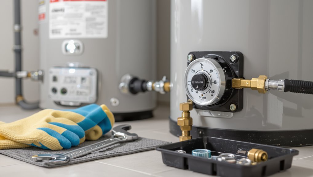
The gas control valve regulates burner operation and maintains the water temperature while incorporating safety features like thermocouples and automatic shutoffs.
Common valve types include manual and thermostatic models, typically comprising a thermostat, pilot assembly, gas inlet, and control knob.
Indicators that a valve may need replacement include persistent temperature fluctuations, inability to light the pilot, gas leaks, or visible corrosion and damage.
Role in temperature regulation and safety
Controls the flow of gas and monitors water temperature, the gas control valve serves as the central regulator that maintains set temperatures and prevents unsafe conditions.
It limits temperature via a thermostat, shuts gas during pilot failure or overheating, and works with safety features like thermocouples.
Understanding this role is essential before attempting how to change gas control valve on water heater.
Common types and parts of gas control valves
A gas control valve on a water heater combines several functions—thermostatic regulation, pilot management, and safety shutoff—into a compact assembly.
Common types include manual, millivolt, standing pilot, and electronic valves.
Typical parts are thermocouple/thermopile, thermostat dial, gas inlet/outlet, and safety solenoid.
Consider compatibility, capacity, and mounting when selecting a replacement.
- Types
- Thermostat
- Safety
- Connections
Signs a gas control valve needs replacement
When should a homeowner suspect the gas control valve is failing? Observable signs include inconsistent water temperature, pilot light outages, unusual gas odors, sizzling or hissing noises, visible corrosion or leaks, and trouble with ignition or maintaining flame.
Repeated burner cycling, unexplained high gas bills, or error codes on digital controllers also indicate malfunction and warrant inspection or replacement by a qualified technician.
Safety Precautions Before You Start
Before beginning work, the technician should verify appropriate personal protective equipment—gloves, eye protection, and flame-resistant clothing—is available and worn.
Gas supply must be shut off and connections tested with a proper leak detector or soapy water before proceeding.
If the leak cannot be isolated, the system is complex, or the person lacks confidence, a licensed gas technician should be contacted.
Required personal protective equipment (PPE)
Donning appropriate personal protective equipment (PPE) reduces the risk of burns, cuts, and inhalation hazards while replacing a water heater’s gas control valve.
The technician should wear gear that protects eyes, hands, skin, and respiratory system during disassembly and handling of components.
- Safety glasses or face shield
- Heat-resistant gloves
- Long-sleeve, flame-retardant clothing
- NIOSH-approved respirator or mask
Gas shutoff and leak testing procedures
Shut off the gas supply at the appliance or main valve and verify zero pressure before loosening any fittings; this eliminates ignition sources and reduces leak risk during the valve replacement.
Confirm closure with a manometer or built-in pressure gauge, then apply soapy-water or approved leak detector to all joints after reassembly.
Ventilate the area, wait recommended dwell time, and recheck before restoring gas.
When to call a professional instead of DIY
Recognize situations that require a professional: if the homeowner lacks experience with gas appliances, if the gas piping or fittings are corroded or damaged, if the water heater’s pilot or ignition systems behave unpredictably, or if local codes or the manufacturer’s warranty mandate licensed-service work.
Additionally, call a licensed technician for persistent leaks, carbon monoxide concerns, complex controls, unclear diagnostics, or when local inspectors require certified repair documentation.
Tools and Replacement Parts You’ll Need
The section lists the essential tools required for the job, such as adjustable wrenches, pipe wrenches, screwdrivers, and a gas leak detector.
It explains how to choose the correct replacement valve by matching model numbers, BTU ratings, and the type of ignition system (pilot light versus electronic ignition).
It also notes additional materials and consumables to have on hand, including pipe thread sealant, replacement gaskets, and appropriate fittings.
Essential tools
A few basic hand tools and the correct replacement parts are required to change a gas control valve safely and effectively.
The technician should prepare a compact set to access fittings, secure connections, and test for leaks while following safety procedures.
- Adjustable wrench and nut drivers
- Screwdrivers (Phillips and flat)
- Pipe thread sealant and tubing cutter
- Manometer and leak detector
Choosing the correct replacement valve (model, BTU, pilot vs. electronic)
After assembling the tool kit, the technician must select a replacement gas control valve that matches the heater’s specifications and operating style. Verify model number, inlet/outlet sizing, and BTU rating; choose pilot or electronic ignition compatible with the existing system. Consult manufacturer manuals and local codes before purchase.
| Requirement | Check |
|---|---|
| Model | Match exact part |
| BTU | Equal or slightly higher |
Additional materials and consumables
Several small consumables and a few specialty parts complement the basic toolkit when replacing a gas control valve on a water heater.
Recommended items include pipe thread sealant or gas-rated PTFE tape, high-temperature RTV or gasket material, replacement thermocouple or thermopile, compression fittings or flare nuts if required, spare pilot tubing, new mounting screws, and fuel-rated flexible connector if the existing one is corroded or damaged.
Preparing the Water Heater for Valve Replacement
Before beginning work, the gas supply and pilot must be turned off to eliminate any risk of ignition.
The water should be shut off at the inlet and the tank drained partially to reduce pressure and prevent spillage.
All gas lines and electrical connections should then be disconnected following safety procedures and local codes.
Turning off the gas supply and pilot
Shut off the gas supply at the house shutoff valve and extinguish the pilot to eliminate fuel flow and prevent ignition during valve replacement.
Confirm closure by attempting to light the pilot or using a gas detector.
Ventilate the area, keep flames and sparks away, and notify household members.
Tag the valve as “DO NOT OPERATE” until the repair is complete and inspected.
Shutting off water and draining the tank partially
Turn off the cold-water supply to the heater at the inlet valve and relieve tank pressure by opening a nearby hot-water faucet.
Attach a garden hose to the drain valve and route it to a safe drain or outdoors.
Open the drain valve slowly and monitor water temperature.
Close the valve when the water level drops below the gas control area to allow safe access.
Disconnecting gas line and electrical connections safely
Wear protective gloves and eye protection while preparing to disconnect gas and electrical lines, and verify the main gas supply is off at the appliance shutoff or meter prior to any work on fittings.
Confirm power is isolated at the breaker. Vent residual gas, use a wrench on appropriate fittings, cap or plug lines, label electrical connections, and follow local codes.
Test for leaks before restoring services.
Step-by-Step: Removing the Old Gas Control Valve
With the heater prepared and gas shut off, the technician first gains access to the control valve by removing any access panels and insulation.
Wires and the thermocouple are labeled and disconnected to guarantee correct reassembly and to prevent accidental cross‑connections.
Finally, the valve assembly is unbolted and withdrawn from the burner tube for replacement.
Accessing the control valve and removing access panels
Begin by ensuring the water heater is completely powered and fueled off, then allow the unit to cool before proceeding.
Locate the burner access door and outer panel. Remove screws securing the lower access panel, then slide or lift it away.
Unscrew the burner box cover to reveal the control valve. Keep fasteners organized and note panel orientation for correct reassembly.
Labeling and disconnecting wires and thermocouple
Before disconnecting anything, the technician should label each wire and the thermocouple to preserve their original locations and guarantee correct reassembly.
Use numbered tags or colored tape and photograph connections for reference.
After labeling, disconnect power at the breaker, then loosen terminal screws and gently remove wires.
Unscrew the thermocouple nut with an appropriate wrench, keeping parts organized for installation.
Removing the valve assembly from the burner tube
Carefully free the valve assembly from the burner tube by first ensuring all fasteners and remaining connections are removed.
The technician should rotate and gently pull the assembly straight out to avoid bending the tube or damaging the gasket surfaces.
Inspect the mating surfaces for debris or corrosion, note gasket condition, and set the old assembly aside on a protected surface for disposal or recycling according to local codes.
Step-by-Step: Installing the New Gas Control Valve
The replacement valve is first inspected for correct model, clean ports, and intact seals before any installation work begins.
The valve is then fitted onto the burner tube, secured with the proper fittings, and pipe sealant is applied to threaded gas connections before tightening to specified torque.
Finally, the thermocouple, pilot tubing, and electrical wiring are reconnected and checked for proper routing and leak-free operation.
Inspecting and prepping the replacement valve
Remove packaging and lay the replacement valve on a clean, well-lit surface to examine it for shipping damage, correct model number, and required fittings.
Verify gasket and O-ring presence, inspect threads and ports for debris, and confirm orientation markings.
Compare mounting holes and thermocouple connection to the old unit.
Gather required tools, thread sealant or tape, and replacement fasteners before proceeding.
Installing valve onto burner tube and securing fittings
With the replacement valve inspected and tools at hand, the technician aligns the valve inlet with the burner tube mouth and seats it squarely to avoid cross-threading.
They hand-start fittings, then tighten with the appropriate wrench to manufacturer torque specifications.
Thread sealant or tape is applied only where specified.
Once secure, connections are visually checked for proper seating and clearance before proceeding.
Reconnecting thermocouple, pilot tubing, and wiring
Reconnect the thermocouple, pilot tubing, and wiring in the precise order recommended by the manufacturer to guarantee safe, reliable operation.
Match fittings and terminals to their original positions, seating the thermocouple tip properly at the pilot flame.
Route pilot tubing without kinks and secure clips to prevent vibration.
Reattach electrical connectors firmly, ensuring correct polarity and snug, corrosion-free contacts before testing.
Applying pipe sealant and tightening gas connections properly
Begin by preparing all gas-threaded joints with an appropriate pipe thread sealant or approved gas-rated PTFE tape, following the valve manufacturer’s recommendations and local code.
Apply sealant evenly to male threads only; avoid contaminating pilot orifices. Hand-start fittings, then tighten with a wrench to manufacturer torque or snug plus a quarter turn.
Inspect for leaks with approved soap solution and correct any seepage.
Reassembly, Testing, and Commissioning
After the new gas control valve is secured, the technician restores water flow and purges air from the tank and downstream lines to prevent sputtering and pressure issues.
They then relight the pilot, set the thermostat to the required temperature, and perform gas leak tests and pressure checks at all fittings.
Finally, the technician verifies proper operation by observing flame characteristics and cycling the unit through normal operating conditions.
Restoring water and purging air from system
With the gas valve and associated fittings secured, the water supply can be reintroduced and the system purged of trapped air to guarantee proper operation and safe combustion.
Slowly open the cold-water inlet, check for leaks, and fill the tank.
Open nearby hot faucets until steady flow and no sputtering occur.
Close faucets, bleed any air from lines, and verify pressure is normal.
Relighting pilot and setting temperature
Once the tank is full and water lines run clear, attention turns to re-establishing the pilot flame and setting the thermostat for safe operation.
Follow the manufacturer’s pilot-light procedure: turn gas knob to pilot, depress, ignite, and hold until thermocouple heats.
Release slowly, confirm steady flame, then rotate thermostat to desired temperature (typically 120°F).
Observe burner ignition and stable operation.
Performing gas leak tests and pressure checks
Begin by verifying all fittings and connections made during reassembly are tight and correctly oriented before introducing gas.
Slowly open the gas supply and use an approved leak-detection solution or electronic detector along joints, valves, and pipe threads. Observe for bubbles or detector alarms for several minutes.
Next, perform a static pressure check with a manometer to confirm supply stability and absence of pressure drops.
Verifying proper operation and flame characteristics
After restoring gas and electrical connections, the technician observes burner ignition and steady-state operation to verify correct valve function and flame characteristics.
He confirms a crisp blue flame with minimal yellow tipping, even distribution across the burner, and stable flame while cycling thermostat.
He records manifold pressure, checks pilot stability, listens for abnormal noises, and guarantees safe venting and no gas odor before concluding the commissioning.
Troubleshooting Common Issues After Replacement
After replacing the gas control valve, common post-service issues can include a pilot that will not light or stay lit, no hot water or intermittent heating, and the presence or smell of gas indicating a possible leak.
Each symptom has specific causes and corrective steps, from cleaning or repositioning the pilot assembly and checking thermocouple function to verifying gas supply and burner operation.
If a gas smell or suspected leak occurs, the immediate action is to shut off the gas supply, ventilate the area, and contact a qualified technician or emergency services.
Pilot won’t light or stay lit causes and fixes
If the pilot won’t light or won’t stay lit after replacing the gas control valve, the problem is usually one of a few specific causes: a faulty thermocouple or thermopile, improper pilot flame size or alignment, debris or blockages in the pilot orifice, or a gas supply/pressure issue.
Inspect and clean the orifice, verify flame envelopes the sensor, test sensor continuity, guarantee correct gas pressure, and replace defective parts.
No hot water or intermittent heating
Confirming whether the new gas control valve resolves temperature problems requires a systematic approach: check that the pilot and burner are operating consistently, verify the thermostat and gas valve settings, inspect for air or sediment in the tank and supply lines, and test for proper gas pressure and thermocouple/thermopile function.
If intermittent heating persists, examine dip tube integrity, circulation patterns, and any bypass or mixing valves for faults or improper installation.
Gas smell or suspected leak immediate actions
Evacuate the area immediately and shut off the gas supply at the appliance or main valve while avoiding any actions that could create sparks.
Notify occupants, call emergency services or the gas utility from a safe location, and do not re-enter until cleared.
Ventilate if instructed by professionals.
Have a qualified technician inspect, repair, and pressure-test the system before restoring service.
Maintenance Tips to Extend Valve Lifespan
A concise maintenance routine helps preserve a gas control valve and prevent unexpected failures.
A checklist should include visual inspection, leak checks, thermocouple condition, and proper ventilation, along with simple preventive steps like keeping the area clean and avoiding corrosive exposure.
Professional servicing is recommended on a regular schedule or immediately if signs of malfunction or gas odor appear.
Routine inspection checklist
When performed regularly, a concise inspection checklist helps detect wear, leaks, and corrosion on the gas control valve before small issues escalate.
The checklist covers visual, functional, and safety checks to document condition and schedule service.
- Inspect for rust, cracks, or loose fittings.
- Check for gas odors and leak detection solution bubbles.
- Verify pilot and burner operation.
- Record readings and corrective actions.
Preventive measures to avoid premature failure
Implementing targeted preventive measures can significantly extend the service life of a water heater’s gas control valve by minimizing corrosion, wear, and malfunction.
Regularly drain sediment, maintain proper ventilation, guarantee secure fittings, and replace degraded gaskets or seals.
Keep surrounding area dry, monitor for gas odors and irregular pilot behavior, and apply manufacturer-recommended lubricants or anti-corrosion treatments sparingly to moving parts.
When to schedule professional servicing
Following routine preventive steps reduces strain on a gas control valve, but professional inspection and servicing remain necessary at set intervals and under certain conditions.
Schedule service annually or per manufacturer recommendations, sooner if irregular pilot behavior, smell of gas, leaking, strange noises, frequent cycling, or after major plumbing or gas-line work.
Professionals should also inspect older units, high-mineral water areas, or persistent temperature inconsistencies.
Cost, Warranty, and Compliance Considerations
Typical replacement costs are outlined, including parts, labor, and potential diagnostic fees.
Readers are reminded to check warranty terms and manufacturer specifications that may affect eligibility and required procedures.
Attention is also drawn to local building codes and permit requirements that can influence legal and safety obligations.
Typical replacement cost breakdown
A clear understanding of the cost components, warranty implications, and compliance requirements helps homeowners anticipate the total expense of replacing a water heater gas control valve. Typical costs include part, labor, permit, and testing fees; regional codes can affect pricing. Budget for inspection and potential upgrades to meet current safety standards.
| Item | Typical Cost |
|---|---|
| Part | $50–$200 |
| Labor & permits | $100–$400 |
Warranty and manufacturer specifications to check
Beyond cost components and permit requirements, checking warranty terms and manufacturer specifications can prevent voiding coverage or installing an incompatible part.
Verify model numbers, approved replacement parts, torque and piping specifications, and any required authorized-service stipulations.
Note warranty durations, transfer restrictions, and documentation needed for claims.
Retain receipts and photos of original parts and installation to support future warranty or service inquiries.
Local codes and permit requirements
When local codes require permits or inspections, homeowners should confirm jurisdictional requirements before replacing a gas control valve to avoid fines or forced rework.
Compliance often mandates licensed personnel, specified materials, and documented inspections.
Permit fees and inspection scheduling add cost and time.
Failure to obtain required approvals can void insurance or warranties and result in citations or mandatory corrective work.
Visual Aids and Reference Diagrams
A clear diagram labeling the valve components and their connections helps readers identify parts and plan safe disassembly.
A concise photo sequence showing each removal and installation step provides visual confirmation of correct technique and orientation.
Together, these visuals reduce uncertainty and support accurate, code-compliant work.
Diagram of valve components and connections
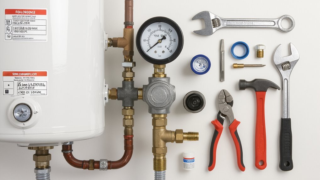
The diagram presents a clear schematic of the gas control valve, showing its main components—thermostat knob, pilot assembly, gas inlet and outlet ports, safety shutoff (thermocouple/thermopile) connection, and mounting interface—and the typical pipe and electrical connections to the water heater.
Labels identify fasteners, gasket locations, and flow direction; callouts note mounting orientation, wiring terminals, and common thread sizes for reference.
Photo sequence of removal and installation steps
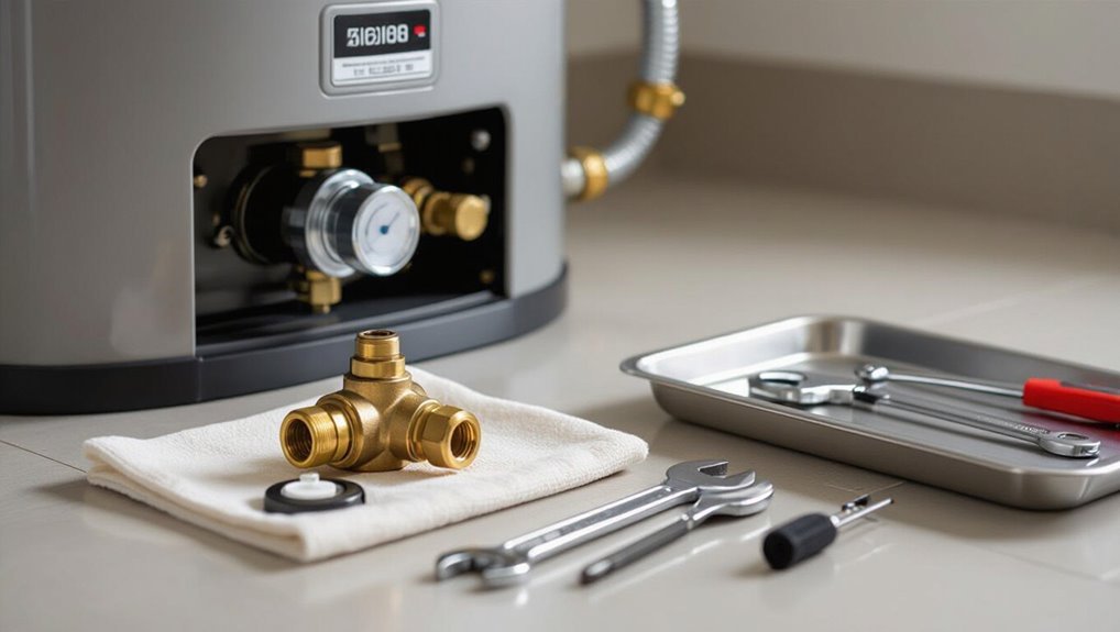
Begin by presenting a clear, numbered photo sequence that guides the technician through each removal and installation step, with each image paired to a concise caption and a corresponding diagram highlighting parts, fasteners, and flow direction.
Include wide shots for context, close-ups for torque points and seal surfaces, arrows for component movement, numbered fastener callouts, and before/after comparison images to verify correct assembly and orientation.
Conclusion
The replaced gas control valve becomes a small compass within the boiler’s belly, steering warmth safely through pipes as seasons turn. After careful precautions, correct parts, and methodical steps, the unit resumes steady service—its pilot light a quiet lantern against cold. Regular maintenance keeps that compass true; adherence to codes and warranties preserves trust. In that steady glow, homeowners find reassurance: practical vigilance transforms mechanical parts into reliable guardians of comfort.

