How to Find a Water Line Without Digging: 7 Proven Non-Invasive Methods
If you need to locate a buried water line without digging, there are seven effective non-invasive methods available. These include inspecting surface clues, using tracer dye or pressure tests, employing acoustic listening, utilizing electromagnetic pipe and tracer-wire locators, conducting thermal infrared scans, and applying ground-penetrating radar. The choice of method will depend on factors like the depth of the line, soil type, pipe material, and budget considerations. Before proceeding, it’s essential to conduct safety checks, notify utilities, and obtain necessary permits. For more detailed guidance on practical steps, equipment selection, and when to consult a professional, see the information below.
How to Locate a Buried Water Line Without Digging
Before attempting to locate a buried water line, one should make a quick assessment to determine whether digging can be avoided or minimized.
Safety and legal checks—such as contacting local utility notification services and reviewing property records—must be completed prior to any locating effort.
These steps reduce risk and guarantee compliance while guiding the choice of non‑invasive locating methods.
Quick assessment: Should you avoid digging?
When evaluating whether digging is necessary, the homeowner should weigh safety, cost, and the likelihood of locating the water line without excavation.
A quick assessment reviews visible clues, property plans, and non-invasive options like tracer gas, line-locators, or ground-penetrating radar.
If risks, unclear maps, or sensitive landscaping exist, prioritizing how to find a water line without digging and hiring specialists is prudent.
Safety and legal checks before locating underground utilities
Although noninvasive locating methods minimize disturbance, confirming safety and legal requirements is essential: utility notification services must be contacted, local permits and easement records reviewed, and any site-specific hazards—such as electrical, gas, or contaminated soils—noted before proceeding.
Professionals should verify maps, call 811 or local one-call centers, document permissions, and use protective measures and insurance checks to mitigate liability and risk.
Overview of Non-Invasive Detection Methods
Non-invasive detection methods vary in accuracy, cost, and suitability depending on soil conditions, pipe material, and required precision.
The article compares common options—such as electronic locators, ground-penetrating radar, and acoustic devices—against those criteria.
Guidance is provided on when a homeowner can attempt a DIY scan and when a professional should be called for safety or certainty.
Comparison of accuracy, cost, and suitability for each method
Because each detection technique relies on different physical principles and equipment, their accuracy, cost, and practical suitability vary considerably; a concise comparison helps users match method to need. A brief table clarifies tradeoffs and typical uses.
| Method | Notes |
|---|---|
| Ground-penetrating radar | High accuracy, moderate cost, best for dry soils |
| Acoustic listening | Variable accuracy, low cost, good for shallow leaks |
| Electromagnetic locators | Accurate for metallic lines, higher cost |
| Thermal imaging | Moderate accuracy, moderate cost, limited by depth |
When to call a professional vs. DIY approaches
When should a homeowner attempt locating a water line alone, and when is professional help warranted?
Homeowners may use maps, metal detectors, acoustic listening, or tracer dye for simple, shallow lines and low-risk zones.
Professionals are recommended for deep mains, suspected leaks, gas/electrical proximity, complex yards, or where permits and liability matter; they offer specialized equipment, accuracy, and safety assurances.
Using a Pipe and Cable Locator
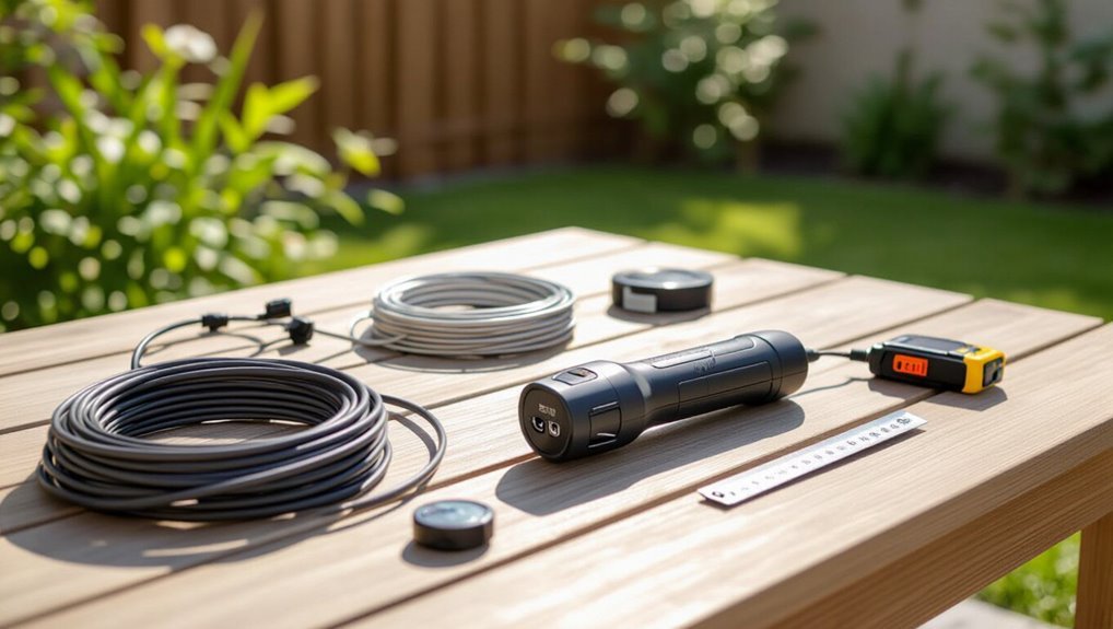
A pipe and cable locator uses a transmitter to inject an electrical signal onto a buried metallic pipe or tracer wire and a receiver to detect the signal above ground, mapping the line’s path.
Typical operation involves connecting or clamping the transmitter, selecting an appropriate frequency, then sweeping the receiver along the surface while noting signal strength and direction.
Performance depends on pipe material, soil conditions, depth, nearby conductive utilities, and operator skill, so success is highest with metallic lines, low-interference environments, and correct frequency selection.
How electronic locators work
Electronic pipe and cable locators operate by inducing or detecting an electrical signal on conductive utilities and then tracing that signal along the line to reveal position and depth.
Receivers sense signal strength and peak directly above the utility; advanced units compute depth from signal amplitude and known transmitter output.
Proper grounding, frequency selection, and interpretation minimize interference and distinguish parallel lines, joints, or breaks.
Step-by-step: using a transmitter and receiver
Begin by setting up the locator components: place the transmitter near the accessible section of the utility, connect its clamp or lead to the pipe or tracer wire, and position the receiver for initial sweeps.
Sweep slowly along the expected route, note strongest signal peaks, mark centerline and depth readings, adjust frequency or gain to confirm, retrace to verify continuity, and record findings for mapping.
Limitations and best conditions for success
Success with a pipe and cable locator depends on predictable conditions and an awareness of the technique’s inherent limits.
Effectiveness drops with non-conductive pipes, deep burial, parallel utilities, strong electromagnetic interference, or poor ground connections.
Ideal results occur with metallic or tracer-equipped lines, shallow depth, minimal nearby conductors, calibrated equipment, and experienced operators who verify readings and combine methods when ambiguity or safety concerns arise.
Acoustic Leak Detection Techniques
Acoustic leak detection uses the characteristic noise of pressurized water escaping from pipes to locate lines without excavation.
Equipment ranges from professional ground microphones and correlators to simple DIY listening sticks and stethoscopes.
Interpreting sounds requires experience to distinguish genuine leaks from background noise and other false positives.
How sound-based detection finds pressurized water lines
Technicians detect pressurized water lines by listening for the distinctive noises produced when water escapes under pressure and interacts with the pipe and surrounding soil.
Acoustic signatures—frequency, amplitude and rhythm—are analyzed to distinguish flow, leaks and background noise. Sound propagates along metallic and plastic pipes differently; technicians triangulate source locations using differential timing and pattern recognition to pinpoint pressurized line positions.
Equipment options and DIY listening methods
Choose from a range of tools when attempting to detect water lines by sound, from professional-grade correlators and ground microphones to simple DIY stethoscopes and smartphone apps; each option balances sensitivity, cost, and required expertise.
Professionals use correlators and contact sensors for accuracy, while homeowners can try metal rods, acoustic amplifiers, or app‑based recorders.
Proper placement and quiet conditions improve results.
Interpreting acoustic signals and false positives
After selecting a listening method or tool, interpreting what is heard becomes the next challenge. The technician distinguishes true leak signatures—steady, turbulent hissing or rhythmic flow—from false positives like traffic, wind, or nearby plumbing.
Cross-referencing multiple sensors, varying pressure, and relocating the device clarify source. Documentation and conservative excavation decisions reduce mistakes and unnecessary disruption.
Ground Penetrating Radar (GPR) for Water Lines
Ground penetrating radar (GPR) locates subsurface utilities by sending electromagnetic pulses into the ground and interpreting reflected signals to reveal contrasts between pipe materials and surrounding soil.
Its effectiveness depends on soil conditions and pipe depth—GPR typically works best in dry, sandy soils and may struggle in clay, highly conductive ground, or at greater depths.
Costs vary by equipment and site complexity, so hiring an experienced GPR operator is often recommended to guarantee accurate data collection and interpretation.
How GPR detects subsurface utilities
GPR emits high-frequency radio waves into the soil and measures the time and strength of returning reflections to reveal buried utilities. Reflections occur where electromagnetic contrasts exist—between pipe material, backfill, and surrounding soil.
Recorded signals produce radargrams; trained operators interpret hyperbolic signatures, continuous linear features, and depth estimates. Data layering and positioning produce maps that guide non-invasive utility locating and verification.
Typical depth and material limitations
Having explained how radargrams and hyperbolic signatures reveal buried utilities, the discussion turns to the practical limits of depth penetration and material detectability for water lines.
GPR typically reaches 0.5–5 meters in soils; sandy, dry ground yields greater depth, while clay or saline conditions severely attenuate signals.
Metallic or plastic pipes produce different reflections; small-diameter or deeply buried non-metallic lines may be indistinguishable from soil noise.
Cost considerations and hiring a GPR operator
Budgeting for GPR services requires weighing equipment, labor, and site factors that influence price. Rates vary by hour, mobilization, and scan complexity; typical jobs range from small flat fees to several hundred dollars per hour.
Hiring a certified operator reduces misreads and liability. Request references, insurance, calibration records, and a clear report format.
Compare quotes and inspect prior work samples before committing.
Electromagnetic Induction and Tracing
Electromagnetic induction and tracing use a transmitter to induce a signal on metal pipes or attached tracer wire so a receiver can follow the route without excavation.
The process typically involves clamping or coupling a signal to the line and sweeping the area while monitoring signal strength and direction.
If the pipe is nonmetallic, poorly connected, or the signal is masked by nearby utilities, alternative methods such as ground-penetrating radar or hydrostatic tracing should be considered.
Using induction to trace metal pipes and tracer wire
Technicians employ induction to trace buried metal pipes and tracer wires by inducing a signal onto the conductor and following its electromagnetic field with a receiver.
The method detects conductive continuity and locates route, bends, and depth estimates using signal strength and peak detection. It works on metallic lines or continuous tracer wire, tolerates shallow soil conditions, and minimizes surface disturbance while requiring calibrated equipment and trained operators.
Steps to attach a signal to a water line
Begin by preparing the tracing equipment and establishing a clear connection point to the water line: confirm the line material and continuity, shut off valves and relieve pressure if needed, clean and expose a metal surface or tracer wire, and select the appropriate transmitter settings and clamp or direct-connection method before energizing the signal.
Attach clamp or direct lead securely, set output level, verify signal on receiver, and document connection.
When this method fails and alternatives
If a direct clamp or direct-connection tracing fails to produce a readable signal, operators should turn to alternative methods such as electromagnetic induction and tracer wire locating.
Electromagnetic induction detects AC or induced fields from buried conductors without contact.
Tracer wire locating uses a conductive path installed with the pipe.
Both require calibrated receivers, careful sweep patterns, and verification to distinguish target lines from adjacent utilities.
Thermal Imaging and Infrared Scanning
Thermal imaging detects temperature differences at the surface that can indicate active water flow beneath, as moving water often produces a cooler or warmer signature compared with surrounding soil.
The method works best when water temperature contrasts with ground temperature and when scans are performed during stable ambient conditions, such as early morning or late evening.
Practical tips include scanning at multiple angles, noting transient hotspots or cold streaks, and correlating images with known pipe routes to avoid misinterpretation.
How temperature differences reveal active water flow
Infrared cameras detect subtle temperature differences at the ground surface that indicate moving water beneath: flowing water absorbs, conducts, and releases heat differently than surrounding soil, so wet zones or active lines often appear as consistent thermal anomalies against the background.
Technicians interpret patterns, gradients, and temporal changes to distinguish true flow from static moisture, mapping probable pipe paths and flow direction for targeted verification.
Best conditions for thermal detection
When environmental contrasts are pronounced, thermal imaging yields the clearest signals for locating buried water lines.
Ideal conditions include calm, dry air, minimal solar heating (pre-dawn or late evening), and stable ground temperatures.
Shallow installations produce stronger signatures; insulated or deep pipes reduce detectability.
Seasonal moisture differences and recent flow variability also enhance contrast, improving the likelihood of reliable thermal detection.
Practical tips for scanning and interpreting images
Following the discussion of ideal environmental conditions, attention turns to practical scanning technique and image interpretation.
Operators should move slowly, maintain consistent camera angle and height, and overlap sweeps to guarantee coverage.
Calibrate emissivity for surfaces, use temperature palettes to highlight contrasts, and record geotagged images.
Interpret patterns, not single frames: linear, repeating temperature anomalies often indicate buried water lines.
Visual Clues and Surface Indicators
Attention to landscaping, pavement patterns, and vegetation can reveal likely water line routes through worn soil, depressions, or unusually lush plant growth.
Utility maps, plats, and visible access points provide corroborating evidence and help narrow search areas.
Combining these surface indicators with detection tools yields a more reliable, noninvasive location strategy.
Signs in landscaping, pavement, and vegetation
Subtle surface cues—patterns in landscaping, pavement distress, and unusual vegetation—often indicate the presence of an underground water line.
Linear greener stripes, soggy patches, or moss bands mirror leaks or moist soil.
Pavement cracks, settled asphalt, or aligned depressions can trace pipe routes.
Consistent plant vigor differences along a path, especially near irrigation valves or meter areas, merit focused, noninvasive investigation.
Following utility maps, plats, and visible access points
Surface indicators often point to where to look, but confirming a pipe’s course usually requires referencing official records and obvious access points.
Utility maps and plats provide recorded easements, line types, and coordinates. Compare those documents with visible markers—meter boxes, curb stops, valves, and maintenance holes—to trace alignment.
Document discrepancies and contact utility holders for verification before any intervention.
Combining clues with detection tools
A few visible clues—discolored pavement, linear vegetation changes, utility markers, and small depressions—can be systematically combined with handheld detection tools to build a reliable picture of an underground water line’s route.
Inspectors correlate sighted patterns with metal detectors, electronic pipe locators, ground-penetrating radar, and acoustic listening devices, prioritizing corroborated signals, documenting offsets, and ruling out other utilities before marking likely alignments for noninvasive confirmation.
Using Tracer Dye or Noninvasive Pressure Tests
Tracer dye can reveal active flow paths by coloring water where lines surface or discharge, allowing detection without excavation.
Noninvasive pressure and shut-off tests help localize a problematic segment by comparing pressure changes and isolating zones.
Both methods have practical limits—dye effectiveness depends on dilution and flow, and pressure testing requires access to valves and may be constrained by system layout or environmental regulations.
How tracer dye can indicate flow without excavation
Several simple dye tests can reveal flow paths without excavation by introducing a visible or fluorescent marker into a known point and observing where it reappears.
Technicians monitor downstream outlets, vents, exposed joints, or catch basins for dye traces, confirming connectivity and approximate flow direction.
Results guide noninvasive mapping, leak identification, and verification of repairs, while minimizing disturbance and excavation needs.
Conducting pressure and shut-off tests to localize a section
Following dye checks to confirm flow paths, technicians move on to targeted pressure and shut-off tests to pinpoint the affected segment.
Valves are isolated systematically while pressure gauges monitor drops; sequential shut-offs localize leaks or dead-ends.
Data logging and comparative readings between sections reveal abnormal losses.
Results guide precise digging or further noninvasive inspection, minimizing disruption and focusing repair efforts efficiently.
Environmental and practical limitations
While tracer dye and noninvasive pressure testing can be effective, their accuracy and applicability are constrained by site-specific environmental and operational factors.
Soil composition, groundwater flow, and turbidity can obscure dye detection. Ambient pressure fluctuations, multiple service connections, and aging infrastructure complicate pressure interpretation.
Regulatory limits on additives, weather conditions, and access restrictions further reduce feasibility, requiring complementary methods or targeted excavation.
Step-by-Step Field Checklist for Finding a Water Line Without Digging
A concise field checklist guides a technician through finding a water line without disturbance, ensuring each step is completed in order and recorded.
Prior to work, tools are prepared and calibrated; scanning and marking follow a clear pattern; verification closes the loop.
Key items to follow include:
- Pre-inspection tasks
- Tool setup and calibration
- Systematic scanning and marking procedures
- Verification procedures
- Documenting findings
Pre-inspection tasks
Prepare the site by confirming access, safety, and available documentation before any detection begins.
Inspect visible landmarks, meter locations, valves, utility markers, and surface conditions.
Verify permits, property boundaries, and utility-company liaison.
Note potential hazards—traffic, vegetation, confined spaces—and record coordinates and baseline photos.
Establish communication plan, emergency contacts, and timing constraints to minimize disruption and guarantee legal compliance.
Tool setup and calibration
Begin by laying out each detection instrument and accessory in a clean, accessible arrangement, ensuring visual inspection for physical damage and correct model/version labels.
Verify batteries, connectors, and antennas; install fresh power sources.
Power on devices, allow warm-up, then set sensitivity, ground balance, and frequency per manufacturer specs.
Perform a known-target check and record calibration settings before field use.
Systematic scanning and marking procedures
With instruments calibrated and verified, the crew moves to a systematic scanning pattern across the work area. They sweep in parallel transects, overlap passes to prevent gaps, and maintain consistent sensor height and speed.
Detected signals are flagged immediately with color-coded markers and temporary stakes. Notes record grid coordinates, signal strength, and environmental conditions for subsequent analysis and handoff.
Verification and documenting findings
Confirm findings through repeat passes and independent methods before finalizing any marks.
The team records GPS coordinates, depths, readings, timestamps, and instrument settings.
Photographs and annotated site sketches accompany notes. Discrepancies trigger rechecks or alternate techniques.
A concise report consolidates raw data, interpretation, and confidence levels for stakeholders.
Securely store all records for regulatory compliance, future reference, and liability protection.
Common Challenges and How to Overcome Them
Operators frequently face interference from nearby utilities and urban clutter that can mask signals and complicate locating efforts.
Variable soil conditions and unexpected burial depths further challenge detection equipment and require adaptive techniques.
Misleading readings are common, so confirmatory methods—such as cross-referencing maps, using multiple sensors, or performing noninvasive verification—are essential.
Interference from other utilities and urban clutter
Many urban areas contain dense networks of buried cables, gas lines, sewers, and telecom conduits that can mask or mimic the signals used to locate water mains.
Locators must distinguish target signatures, employ multiple detection methods (acoustic, electromagnetic, ground-penetrating radar), cross-reference utility maps, and coordinate with utility owners.
Systematic verification and careful signal interpretation reduce false positives and improve accuracy.
Difficult soil types and buried depth issues
When soils range from loose sandy deposits to dense clay or rocky fill, and water mains sit at varying depths, locating signals can weaken, scatter, or be obscured; overcoming these conditions requires adapting equipment settings, selecting complementary detection methods, and planning targeted verification.
Practitioners adjust transmitter frequencies, increase receiver sensitivity, combine ground-penetrating radar with electromagnetic tracing, and schedule multiple passes to map depth changes and minimize false negatives.
Misleading readings and how to confirm accuracy
Even with optimized settings and multiple sensing methods, readings can still mislead: electromagnetic interference, nearby metallic utilities, soil conductivity anomalies, and frozen or saturated layers may create false positives or mask the target.
To confirm accuracy, cross-check with a different technology, perform repeat surveys at varied frequencies and orientations, validate against utility maps, and verify probe points or small test excavations before major work.
When to Hire a Professional Locator
When buried lines are deep, complex, or inconsistently mapped, a homeowner should consider that the task exceeds typical DIY capability.
The article will outline how to vet locators—checking certifications, references, equipment, and insurance—so readers can choose a reliable service.
It will also summarize typical costs and expected turnaround times to set realistic expectations.
Signs the job exceeds DIY capability
Several clear indicators show the task has outgrown DIY methods and warrants a professional locator.
Complex property layouts, multiple utility types, or undocumented lines increase risk.
Persistent unexplained leaks, repeated failed locating attempts, or local regulations requiring certified locators also demand expertise.
When safety, potential for costly damage, or project timelines are at stake, engaging a professional becomes the prudent choice.
How to vet and choose a locating service
A handful of clear criteria help property owners distinguish competent locating services from inexperienced ones: proper licensing and insurance, up-to-date locating equipment, verifiable references, and familiarity with local utility maps and regulations.
Evaluate credentials, ask about detection methods (electromagnetic, ground-penetrating radar), verify insurance and bonding, request recent job references, confirm regulatory compliance, and prefer firms offering written reports and clear liability limits.
Expected costs and turnaround times
Many homeowners weigh cost and timing as the primary factors in deciding whether to hire a professional locator.
Typical rates range from a flat fee for a single mark-up to hourly charges for more complex surveys, while turnaround can span from the same day for emergency calls to several days for scheduled jobs or GPR analysis.
Costs vary by region, scope, depth and required permits; ask for written estimates and availability.
Preventive Measures to Avoid Future Locating Problems
Preventive steps can greatly reduce future difficulty in locating water lines. Recommended measures include installing tracer wire and clearly labeling new pipes, maintaining accurate as-built records and maps, and following landscaping practices that preserve access to utilities.
Implementing these practices creates a reliable reference for homeowners and technicians when non-dig locating is required.
Installing tracer wire and labeling new lines
Install tracer wire alongside newly installed water lines to guarantee future locatability and reduce the need for exploratory digging.
Attach continuous, corrosion-resistant conductor to pipe or conduit, securing at regular intervals.
Terminate ends in accessible, labeled test points and tie into signal transmitters where appropriate.
Use durable, weatherproof surface markers indicating depth, direction, and installation date to aid future detection and maintenance.
Keeping accurate as-built records and maps
After placing tracer wire and marking test points, project teams should maintain thorough as-built records and updated maps to guarantee future locatability without excavation.
Records must include GPS coordinates, depths, pipe materials, connector locations, tracer wire routing and test results.
Digital maps with version control, standardized naming, and secure backups enable accurate sharing with operators and locators, reducing misidentification and unnecessary digging.
Best practices for landscaping and utility access
A combination of thoughtful landscaping decisions and clear access provisions greatly reduces future locating challenges for buried utilities.
Property owners should mark utility corridors, use tracer wires and detectable warning tape, and avoid deep-rooted plantings above lines.
Maintain accessible valve boxes, create durable service easements, and document locations in visible maps.
Regular inspections and coordination with utility providers prevent accidental damage and simplify future locating.
Conclusion
Locating a buried water line without digging is feasible using non-invasive tools and techniques described. Although some may worry these methods are unreliable, combining a pipe and cable locator, acoustic detection, and GPR greatly improves accuracy while avoiding costly excavation. For complex sites or uncertain results, hiring a professional locator guarantees safety and precision. Adopting preventive mapping and markers prevents future uncertainty, saving time and reducing risk on subsequent projects.