How to Open a Rinnai Tankless Water Heater: Step-by-Step Guide for Safe Access
To safely open a Rinnai tankless water heater, ensure the unit is powered down, gas and water are shut off, and pressure is relieved. Verify proper ventilation before proceeding. Locate the model plate, gather necessary tools, personal protective equipment (PPE), and the relevant service manual. Remove panels in the correct order, label wiring, and take photographs of components for reference. Inspect the heat exchanger, burners, and sensors for any scale buildup or damage. After inspection, reassemble the panels, restore gas and water supplies, and test for leaks and proper ignition. Follow this guide for detailed step-by-step procedures and essential safety checks.
Overview of Accessing a Rinnai Tankless Water Heater
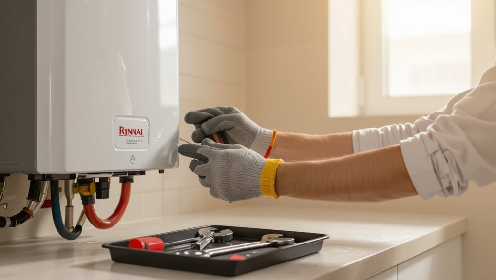
The section explains common reasons to open a Rinnai tankless water heater, such as inspection, maintenance, or part replacement.
It summarizes essential safety warnings and precautions including power and gas shutoff, ventilation, and protective equipment.
A concise tools and materials checklist is provided so the task can be performed efficiently and safely.
Why you might need to open the unit
Accessing a Rinnai tankless water heater becomes necessary for routine maintenance, troubleshooting, and occasional part replacement.
Technicians or informed owners may open the unit to clear scale, inspect heat exchanger and burners, replace sensors or valves, and diagnose error codes.
Knowing how to open Rinnai tankless water heater aids timely repairs, preserves efficiency, and prevents minor issues from escalating into costly failures.
Basic safety warnings and required precautions
Routine inspections and minor repairs often require opening a Rinnai tankless water heater, but doing so carries risks that must be managed before any panel is removed.
Technicians should disconnect power and gas, shut off water supply, ventilate the area, and allow the unit to cool.
Verify absence of pressure and gas leaks; wear protective gloves and eye protection.
Follow manufacturer warnings and local codes.
Tools and materials checklist
Before beginning any work, technicians should assemble a concise checklist of tools and materials tailored to the Rinnai tankless model at hand, ensuring efficiency and safety during access.
Necessary items include precision screwdrivers, adjustable wrench, multimeter, gasket replacements, thread sealant, safety gloves, eye protection, flashlight, and soft cloths. Recommended spares and model-specific manuals minimize downtime.
- Screwdrivers and wrench set
- Multimeter and flashlight
- Gaskets, sealant, cloths
- PPE and manual
Identify Your Rinnai Model and Manual Resources
The technician locates the model and serial number on the unit’s data plate—usually inside the front panel or on a side label—to confirm exact parts and procedures.
They consult the Rinnai service manual, matching the model number to diagrams, safety warnings, and step-by-step instructions for accessing panels and components.
If the manual indicates complex disassembly, gas or combustion work, or unclear fault diagnosis, a qualified professional is recommended over DIY.
Locating the model and serial number on the unit
Locating the model and serial number on a Rinnai tankless water heater is the first concrete step toward finding the correct manual, replacement parts, or service guidance.
The information appears on a metal or vinyl label on the unit’s exterior—typically inside the access panel, on the side, or near the inlet/outlet piping.
Record both numbers accurately before proceeding.
Where to find and how to read the Rinnai service manual
With the model and serial numbers recorded, the next step is locating the correct Rinnai service manual to guarantee procedures match the specific unit.
Manuals are available on Rinnai’s official website under Support > Manuals or via authorized dealer portals.
Verify model code, download the PDF, and consult sections: safety warnings, disassembly diagrams, parts lists, and troubleshooting charts before beginning any access or maintenance.
When to call a professional versus DIY
When should one tackle a Rinnai tankless water heater versus calling a professional?
One should attempt DIY for basic tasks: panel removal, visual inspections, and following the model-specific manual.
Call a licensed technician for gas, electrical, internal component repairs, persistent error codes, or if uncertainty about model specifics exists.
Safety, warranty preservation, and code compliance favor professional service when risks or complexity rise.
Pre-Access Preparations
Before accessing the unit, power and gas must be shut off and the water supply isolated while system pressure is safely relieved.
Attention should be given to venting and combustion air requirements to prevent hazardous fumes or backdrafting.
Appropriate protective gear and a clear, well-lit workspace should be established prior to any panel removal.
Turning off power and gas supply safely
Shut off the electrical supply and gas feed to the Rinnai unit to eliminate ignition and shock risks before any access.
The technician confirms breaker(s) are off at the panel and tags them, then closes the gas shutoff valve supplying the heater.
Electrical lockout and gas valve securement are verified visually.
If uncertain, contact a licensed electrician or gas technician before proceeding.
Shutting off water supply and relieving system pressure
Isolate the water feed and depressurize the system to prevent leaks and scalding during access.
Close the cold-water isolation valve and open a nearby hot faucet to relieve pressure.
Drain inlet and outlet lines using service valves or attached hoses into a bucket.
Verify pressure gauge reads zero.
Inspect for residual water in condensate or drain pans before removing panels.
Venting and combustion air considerations
Proper venting and adequate combustion air are critical to safe access and servicing of a Rinnai tankless water heater.
Technicians should verify vent terminations, clear obstructions, confirm proper vent material and slope, and guarantee intake air sources meet manufacturer clearances and local codes.
Sealed combustion units require intact ducts; atmospheric units need sufficient room or dedicated louvers to prevent backdrafting and CO hazards.
Protective gear and workspace setup
Donning appropriate personal protective equipment and arranging a clear, well-lit work area reduces risk during service access.
The technician guarantees isolation of power and gas, clears combustible materials, and positions tools within reach. Lighting and ventilation are confirmed before opening panels.
- Safety glasses, gloves, and hearing protection
- Non-slip footwear and knee pads
- Portable work light
- Tool tray and labeled fastener containers
Step-by-Step Guide to Opening the Outer Cover
The technician first inspects the unit exterior for screws, clips, or latches and notes their locations.
Next, the front panel is removed in a clear step sequence while electrical connectors and control panels are separated using proper safety precautions.
Removed panels and small parts are labeled and stored to prevent loss or damage.
Inspecting the exterior for screws, clips, or latches
Before attempting to open the unit, one should visually scan the outer housing for fasteners—screws, spring clips, or latches—that secure the cover.
Note locations, types, and any hidden retainers along edges or behind panels. Check for tamper stickers, plastic tabs, or recessed screws requiring specific drivers.
Photograph positions if needed. Confirm power and gas are off before any manipulation.
Removing the front panel: step sequence
Begin by confirming that gas and electrical supplies remain shut off and any nearby fittings are cool to the touch.
Remove visible screws or release clips in sequence: top first, then sides, then bottom.
Support the panel with one hand while loosening fasteners.
Tilt panel outward gently, disengage locating tabs, and lift straight off.
Place panel on a clean, stable surface to avoid damage.
Separating electrical connectors and control panels safely
With the front panel set aside and access to internal components clear, proceed to separate electrical connectors and the control panel following a strict safety-first approach. Power must remain disconnected.
Identify connector locking tabs, depress gently, and pull straight to avoid pins bending. Support the control panel to prevent strain on wiring.
Note connector orientation for reassembly and avoid forcing any stuck plugs.
Handling and storing removed panels and parts
After removal, each panel and component should be cataloged, labeled, and placed on a clean, stable surface to prevent damage and simplify reassembly.
Protective padding separates sharp edges; small parts go into labeled bags. Heavy items rest low to avoid tipping.
Photographs record orientation and fastener locations for reference.
- Panels on padded bench
- Screws in numbered bags
- Fragile parts cushioned
- Photos with notes
Accessing Internal Components
Once the outer cover is removed, the technician identifies the heat exchanger, gas valve, control board, and sensors by their labeled positions.
The heat exchanger cover is unfastened for inspection while wiring harnesses and tubing are disconnected, tagged, and set aside to preserve orientation.
A brief visual checklist is then used to note corrosion, cracks, loose connections, or thermal damage before reassembly.
Locating key internal components (heat exchanger, gas valve, control board, sensors)
A clear understanding of the internal layout helps locate the heat exchanger, gas valve, control board, and sensors inside a Rinnai tankless water heater.
The heat exchanger sits centrally and connects to inlet/outlet plumbing.
The gas valve is near the burner assembly at the lower front.
The control board mounts to the chassis side or front.
Sensors (temperature, flame) attach adjacent to respective components.
How to remove and inspect the heat exchanger cover
Begin by confirming the unit is fully powered down, gas and water supplies are shut off, and the area is cool to the touch; then remove the outer cabinet screws and lift off the front panel to expose the heat exchanger cover.
Unscrew fasteners securing the cover, lift it straight off, inspect fins and passages for scale, debris, or corrosion, and note any damaged seals or severe buildup for service.
Disconnecting and labeling wiring harnesses and tubing
Power should be verified off and the work area cool before any connectors are touched; then each wiring harness and tubing run is systematically disconnected and clearly labeled to preserve original routing.
Technicians document connector locations, note connector orientations, and use durable tags or numbered tape.
Quick-release clips are released gently; harnesses are not pulled.
Tubing is capped to prevent contamination and loss of fittings during reassembly.
Visual checklist for common wear or damage
With the cover removed and components exposed, the technician performs a systematic visual inspection to identify common signs of wear or damage before deeper disassembly.
Check for corrosion on heat exchanger fins, mineral buildup, cracked or brittle wiring insulation, loose or corroded connectors, oil or coolant leaks, scorched or warped circuit board areas, damaged fan blades, and compromised seals or gaskets.
Record and tag any defects.
Common Tasks After Opening (What You Can Do Yourself)
Once opened, the unit allows simple maintenance tasks such as cleaning the burner and combustion chamber.
The homeowner can also flush or inspect the heat exchanger, replace anode rods, filters, and other consumables, and reset error codes for basic diagnostics.
These procedures restore performance and can prevent common issues when performed carefully and according to the manual.
Cleaning the burner and combustion chamber
Remove loose debris and carbon buildup from the burner and combustion chamber before reassembling the unit to guarantee efficient, safe operation.
Use a soft brush and vacuum with a crevice tool, avoiding metal scrapers that can damage surfaces.
Inspect burners for corrosion or blocked ports; gently clear deposits.
Verify seals and gaskets remain intact.
Reinstall components per manufacturer torque and alignment specifications.
Flushing or inspecting the heat exchanger
Inspecting and flushing the heat exchanger guarantees ideal performance and prevents scale buildup that reduces flow and efficiency.
The technician visually checks for corrosion, blockages and leaks, then circulates descaling solution per manufacturer instructions using isolation valves.
Flush until clear water runs, rinse thoroughly, and verify no residual solution remains.
Reassemble panels, restore supply, and test for proper operation and normal temperatures.
Replacing anode/filters or simple consumables
Change or clean simple consumables—such as sacrificial anode rods, inlet strainers, and inline filters—before reassembling the unit to maintain corrosion protection and prevent debris from impairing flow or sensors.
Inspect parts for wear, replace corroded anodes, and rinse or swap filters per manufacturer specs.
Use correct replacement parts, lubricate O‑rings lightly, and torque fittings to recommended values to guarantee reliable seals.
Resetting error codes and basic diagnostics
After servicing the unit, technicians should clear stored error codes and perform basic diagnostics to confirm the heater operates normally.
They reset codes via the control panel or remote per manufacturer instructions, cycle power, and observe ignition, flame, and water temperature response.
Diagnostic checks include visual inspections, error log review, and simple gas/water flow verification.
Document findings and advise further service if faults persist.
Reassembly and Safe Restart Procedure
Reassembly begins with verifying and reconnecting electrical and gas lines, followed by reinstalling panels and tightening all fasteners.
The technician then restores water, gas, and power in the manufacturer-recommended sequence and brings the unit online.
Final checks include testing for leaks, confirming proper ignition, and ensuring the heater operates without error codes.
Reconnecting electrical and gas lines checks
Begin by visually inspecting and confirming that all internal wiring harnesses and gas fittings are clean, undamaged, and correctly routed before any connections are made.
Reconnect electrical connectors firmly, ensuring proper polarity and secure locking tabs.
Tighten gas fittings to manufacturer torque specs, then perform a leak test with soapy solution or electronic detector.
Verify grounding and restore power and gas following local codes and appliance instructions.
Reinstalling panels and securing fasteners
Secure the access panels and fasteners in the original order, ensuring each screw, clip, and seal is correctly seated and torqued to the manufacturer’s specifications.
Confirm gasket alignment and compression, replace any damaged hardware, and tighten progressively to prevent distortion.
Verify panel engagement by gently pulling edges and checking latches.
Document fastener locations and torque values for future maintenance records.
Restoring water, gas, and power in correct order
Restore services in the precise sequence prescribed by Rinnai to prevent damage and guarantee user safety: water first to purge air from the system, gas second to supply fuel once plumbing is confirmed leak-free, and electrical power last to enable controls and ignition.
Technicians should open water valves slowly, verify fittings visually, restore gas at the meter or supply valve, then reapply power, observing normal startup indications.
Testing for leaks, proper ignition, and error-free operation
With the system reassembled and utilities reinstated in the correct order, the technician conducts a methodical check for leaks, confirms reliable ignition, and verifies error-free operation before leaving the unit in service.
- Inspect joints and valves for drips under pressure.
- Observe gas valve and burner during startup.
- Monitor control panel for faults and error codes.
- Run hot-water cycles to confirm stable temperature and no alarms.
Troubleshooting Problems Found During Access
During access, the technician should note common error codes and their likely causes to guide further steps.
If a gas smell or leak is detected, the unit must be shut off and gas supply closed before evacuating the area and contacting the gas company or a qualified technician.
If the unit fails to ignite after reassembly or shows signs such as persistent burning odors, carbon monoxide alarms, or visible damage, professional service is required immediately.
Common error codes and likely causes
A list of common Rinnai error codes and their likely causes helps technicians quickly identify faults encountered while accessing the unit. Typical codes indicate ignition failure, flame loss, sensor errors, or overheat conditions; causes include gas supply issues, clogged burners, faulty thermistors, or blocked vents.
| Error Code | Likely Cause |
|---|---|
| C1 | Ignition failure |
| C3 | Flame loss |
| A1 | Thermistor fault |
| U0 | Overheat/blockage |
What to do if you detect a gas smell or leak
If a gas smell or suspected leak is detected while accessing the Rinnai tankless water heater, immediately stop work, evacuate everyone from the area, and move to fresh air before taking further action.
Once safe, do not operate electrical switches or flames. From outside, shut off the gas supply if trained.
Notify the gas utility or emergency services and a qualified technician; do not re-enter until cleared.
If the unit won’t ignite after reassembly
After confirming no gas leak and returning to the unit, proceed to check ignition if the Rinnai tankless water heater fails to light following reassembly.
Verify power supply, reset breakers, and inspect wiring connections and control board LEDs.
Confirm gas valve is open and inlet filter clear.
Cycle the power and attempt ignition.
If still dark, document error codes and consider calling a qualified technician.
Signs that require immediate professional service
When access reveals smells of gas, persistent burning odors, visible flame roll-out, significant corrosion, warped components, scorch marks, or electrical sparking, professional service is required immediately.
Technicians should inspect gas lines, heat exchanger integrity, venting, and electrical systems. Continued operation risks fire, explosion, carbon monoxide, or further equipment failure.
Isolate fuel and power, ventilate the area, and arrange certified service without delay.
Safety Tips, Maintenance Schedule, and Record-Keeping
The section outlines a concise routine maintenance checklist with recommended frequencies for filters, flushing, and burner inspections.
It also covers long-term measures to prevent scale and corrosion, such as descaling intervals and water treatment options.
Finally, it emphasizes documenting each service action and any parts replaced to maintain a clear service history.
Routine maintenance checklist and frequency
Although routine maintenance may seem minor, adherence to a concise checklist and schedule is essential for safe, efficient operation and warranty compliance.
- Inspect exterior and venting monthly for damage or obstructions.
- Check error codes and reset procedures after each service.
- Clean air intake and burner access panels every six months.
- Document date, technician, findings, and corrective actions in a log.
Long-term care to prevent scale and corrosion
Maintain vigilance against scale and corrosion through a targeted program combining routine descaling, corrosion control, and diligent records to preserve efficiency and safety.
Inspect anode rods, sacrificial components, and heat exchanger condition annually. Implement water-softening or scale inhibitors where hardness warrants.
Use manufacturer-approved descaling procedures and inhibitors. Schedule professional corrosion assessments periodically and log findings, treatment dates, and corrective actions for trend monitoring.
Documenting service actions and parts replaced
Begin each service visit by recording the date, technician name, odometer-like runtime hours (if available), and a concise list of actions performed and parts replaced, including part numbers and serials where applicable.
Maintain a centralized log (digital and/or physical), note warranty implications, attach invoices and photographs, and flag recurring failures.
Use consistent abbreviations, timestamp entries, and store backups for auditability and future diagnostics.
Parts, Warranty, and When to Hire a Technician
Before attempting repairs, the owner should verify warranty status and service coverage through Rinnai’s online registry or by contacting customer support.
Genuine replacement parts are available from authorized dealers and Rinnai’s parts catalog to guarantee compatibility and safety.
If repairs involve gas, combustion components, or complex diagnostics, a licensed technician should be hired, with expected costs varying by labor rates, parts, and travel.
How to verify warranty status and service coverage
How can an owner quickly confirm what parts and labor are covered under a Rinnai tankless water heater warranty?
The owner should locate the model and serial number, review the original warranty booklet or Rinnai’s online database, and register the product if needed.
For ambiguous cases, contact Rinnai customer support with documentation and installation date to determine coverage and any required service authorization.
Sourcing genuine Rinnai replacement parts
Locate genuine Rinnai replacement parts through official channels to guarantee compatibility and preserve warranty coverage: authorized dealers, Rinnai’s website parts catalog, and certified service technicians provide verified components, while third-party vendors may sell compatible but non-genuine items that can void warranty or reduce system reliability.
Record part numbers, purchase receipts, and OEM labels; confirm serial/model fitment before ordering to avoid incorrect components.
What to expect from professional service and cost factors
After securing genuine Rinnai replacement parts and confirming model fitment, homeowners should understand what professional service typically involves and which cost factors to expect.
Technicians inspect diagnostics, venting, gas connections, and combustion; replace parts under warranty when applicable; and provide labor estimates.
Costs vary by labor rates, part prices, travel, and emergency fees.
Hire a licensed technician for complex repairs or safety concerns.
Conclusion
In conclusion, the guide empowers readers to cautiously access a Rinnai tankless water heater, likening the process to lifting a curtain to reveal a stage of careful mechanics. By identifying the model, preparing tools, following the stepwise cover removal, inspecting internals, and reassembling with safe restart checks, most routine maintenance is achievable. Clear records, scheduled upkeep, and knowing warranty limits help decide when a qualified technician should be called.