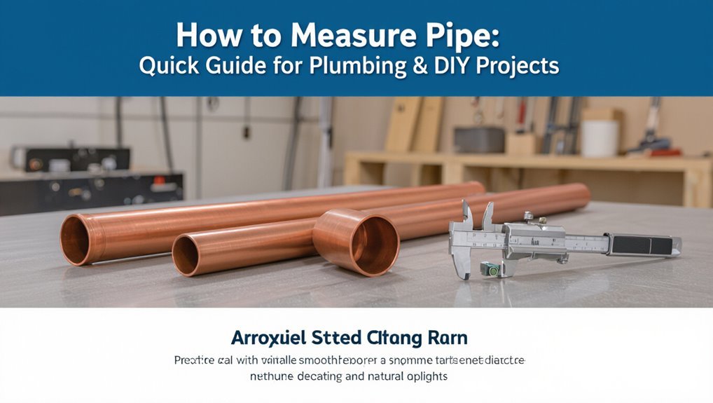
How to Measure Pipe: Quick Guide for Plumbing & DIY Projects
To measure a pipe accurately, first determine whether you need the outside diameter (OD) or inside diameter (ID). For precise measurements, use calipers for small pipes, and a tape measure or OD tape for larger ones. For in-service pipes, ultrasonic gauges can help measure wall thickness. Always measure perpendicular to the pipe’s axis and take multiple readings to account for any ovality. If you need the ID and don’t have special tools, you can measure the circumference and divide it by π, or use a flexible tape inside the pipe. Remember to mark your cut lines and consider the depths for fittings and sealants as well.
Measure Pipe Diameter (OD & ID) Quickly
When measuring pipe diameter quickly, a technician first determines whether outside diameter (OD) or inside diameter (ID) is required, since many fittings and charts reference one or the other; OD is measured across the pipe’s exterior, ID across the internal bore.
The technician uses calipers for precision, noting wall thickness when only OD is accessible. For flexible or corrugated tubing, a ruler across several diameters averages irregularities.
Record measurements in millimeters and inches as needed, and compare to nominal pipe sizes rather than raw measurements. Clean ends and remove scale to avoid false readings that can misfit couplings or seals.
Choose the Right Measurement Method for Your Job
When selecting a measurement method, the technician first confirms the outside diameter to make sure fittings and clamps will match.
Next, wall thickness is checked to verify strength, flow characteristics, and corrosion allowance.
The chosen tools and techniques depend on whether OD or wall measurements are primary for the job.
Measure Outside Diameter
Measure the outside diameter (OD) of a pipe by selecting the method that matches the pipe material, available tools, and required accuracy: calipers for precise metal or plastic pipes, a tape measure for larger or flexible pipes, and specialty OD gauges for fittings where access is limited.
The examiner records measurements at multiple points around the circumference to detect ovality, notes whether measurements include coating or insulation, and converts units when necessary.
For buried or fixed systems, use indirect measuring techniques and manufacturer specs.
Accurate OD supports proper fitting selection and avoids leaks or mechanical stress.
- Use calipers for tight tolerances
- Tape for long runs
- OD gauges for confined spaces
- Record multiple readings
Check Pipe Wall Thickness
After confirming outside diameter, attention turns to wall thickness, since it determines strength, pressure rating, and compatibility with fittings.
A caliper or micrometer measures wall thickness directly on cut pipe; take multiple readings around the circumference for accuracy.
For in-service pipes, ultrasonic thickness gauges provide noninvasive measurements through the wall.
Reference material specifications or pipe charts to convert nominal sizes and schedules into expected thickness values.
When replacing or connecting, match measured thickness to required pressure classes and fitting tolerances.
Record measurements and acceptable tolerances, and when uncertain, consult manufacturer data or a professional to guarantee safety and code compliance.
Tools Primer: Caliper, Tape, Ruler – When to Use Each
Which tool fits a job depends on required accuracy, object shape, and access. The caliper suits precise work and small diameters, offering digital or vernier readings for tight tolerances. A tape measure handles long runs and rough layout where millimeter precision is unnecessary. A rigid ruler provides straight-edge checks and short measurements when stiffness prevents sagging. Choice considers pipe material, visibility, and whether interior measurements are needed.
- Caliper: high precision, limited reach
- Tape: long distance, flexible around curves
- Ruler: short, straight measurements, stable reference
- Combination: use complementary tools for verification
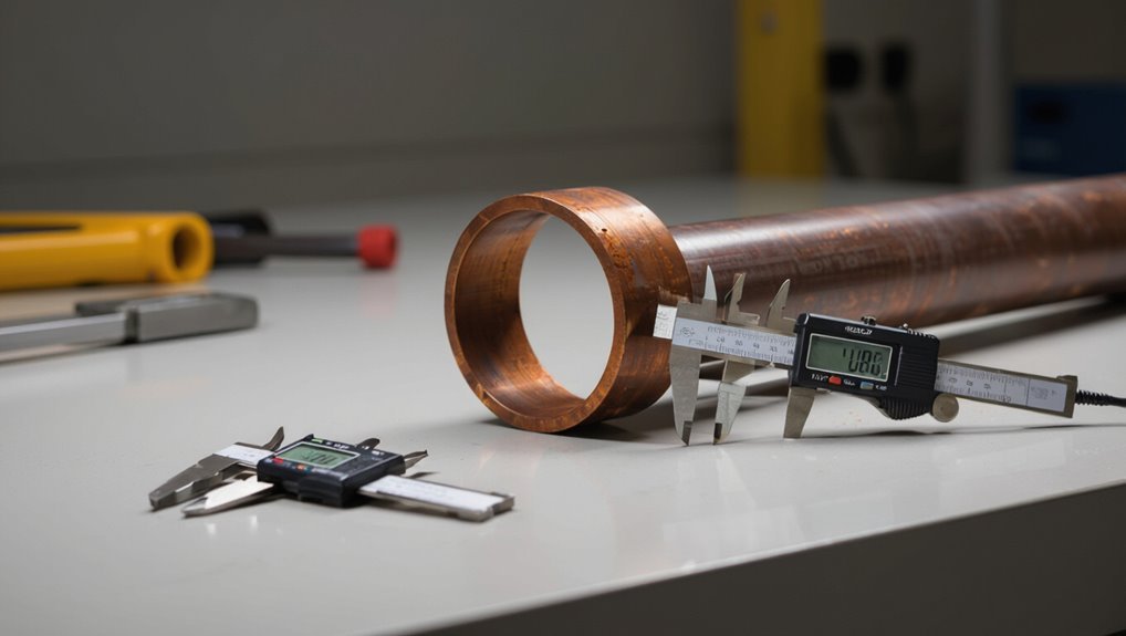
How to Measure Pipe Outer Diameter (OD)
Determining a pipe’s outer diameter (OD) begins with selecting the appropriate instrument and positioning it perpendicular to the pipe axis to avoid skewed readings.
For small pipes, a caliper provides the most accurate measurement: close jaws gently around the exterior, read the digital or vernier scale.
For larger pipes, use a flexible tape measure around the widest external circumference and divide by pi for diameter, or employ an OD tape marked directly in diameter.
Note measurement units and convert as needed.
Record multiple readings at different points to detect ovality and report the largest consistent value for fitting and fabrication.
How to Measure Pipe Inner Diameter (ID) Without Special Tools
Measuring a pipe’s inner diameter (ID) without specialized tools can be done accurately with common items once the outer diameter is known or can be estimated. The method uses simple subtraction: ID = OD − 2 × wall thickness.
Wall thickness can be assessed with calipers, a ruler and feeler gauges, or by measuring an accessible cut end. For fittings without visible walls, use a flexible tape or string inside, mark the circumference, then divide by π (3.1416) to get ID. Verify by sliding a known-size object.
- Measure OD precisely
- Determine wall thickness
- Use circumference-to-diameter method
- Confirm with a gauge
Nominal Pipe Size vs. Actual OD/ID: What Those Numbers Mean
The article explains that nominal pipe size is a reference label rather than an exact measurement, originating from historical standards and used for matching fittings.
It contrasts nominal size with the actual outer diameter (OD) and inner diameter (ID), noting that OD and ID must be measured directly to guarantee proper fit and flow.
Practical guidance on how to measure OD versus ID follows to help readers apply these distinctions in plumbing and DIY projects.
Nominal Size Explained
In conversations about plumbing, nominal pipe size (NPS) often causes confusion because its number does not directly state the pipe’s outside or inside diameter; instead, it serves as a standardized label that groups pipes by capacity and fitting compatibility. The term simplifies specification across materials and schedules, linking a size name to expected flow and compatible fittings rather than precise measurements.
Users should treat NPS as a reference, consult manufacturer tables for actual dimensions, and verify material-specific variations when selecting components. Clear understanding prevents mismatches and guarantees proper joints, seals, and system performance.
- NPS is a naming convention
- Actual OD/ID vary by material
- Schedule affects wall thickness
- Tables give precise dimensions
Measuring OD vs ID
After explaining how nominal pipe size functions as a labeling system, attention shifts to how those labels relate to actual outside and inside diameters.
The distinction matters: nominal size often corresponds to approximate interior flow capacity for older pipe types, while actual outside diameter (OD) and inside diameter (ID) are measurable physical dimensions.
OD determines fit with fittings, brackets, or slip joints; ID determines flow area and pressure characteristics.
Wall thickness links OD and ID and is specified by schedule or standard.
For accurate selection, installers measure OD and ID directly or consult manufacturer charts converting nominal size to true dimensions for each material and schedule.
How Pipe Schedule (Wall Thickness) Affects ID, OD, and Fittings
When wall thickness increases for a given nominal pipe size, the internal diameter decreases while the outside diameter remains constant for most rigid pipe systems. This relationship influences flow capacity, pressure rating, and compatibility with fittings. Thicker walls raise pressure class but reduce ID, altering fluid velocity and required pump sizing.
Fittings designed for a nominal size assume specific IDs or joining methods; mismatches cause leaks or assembly issues. Understanding schedule numbers guarantees correct part selection and performance prediction.
- Schedule changes affect flow rate and pressure capacity.
- OD consistency preserves external coupling fit.
- ID variation alters hydraulic calculations.
- Specify schedule when ordering fittings.
Measure Pipe Length and Mark Cuts for Fittings
Having confirmed pipe schedule and chosen compatible fittings, the next step is to measure pipe lengths and mark precise cut points for those fittings.
Measure from fixed reference points—wall, flange, or existing pipe centerline—to each fitting face, accounting for fitting insertion or socket depth.
Add or subtract length allowances specified by the fitting manufacturer; when using couplings or unions, include gap tolerances.
Transfer measurements onto the pipe with a pencil or scribe, using a square for 90° cuts and angle guides for miters.
Double-check each mark before cutting; miscuts waste material and complicate alignment.
Measure Threaded Pipe and Threaded Fittings Accurately
For threaded pipe and fittings, accurate measurement requires accounting for thread engagement, thread runout, and any sealant or tape thickness to make certain proper final length and alignment. The technician measures from the sealing face or shoulder, not the thread crest, allowing for the portion that will be consumed by engagement. Use calipers to verify major and minor diameters and thread pitch gauges to confirm NPT, BSP or other standards. Account for tape thickness by reducing measured pipe length by the expected compression amount. Verify fit with dry assembly before final sealing to prevent misalignment or leaks.
- Measure to the sealing face
- Use calipers and gauges
- Subtract sealant compression
- Dry-fit before sealing
Measuring Flexible Hose and Corrugated Pipe Correctly
Typically, measuring flexible hose and corrugated pipe requires accounting for bend radius, compressed length, and end fittings so the finished assembly fits without strain.
Measurements should record overall installed length between connection points along the planned routing, noting any curves.
Add the hose’s minimum bend radius to prevent kinking and allow for movement; measure along the centerline of bends.
For corrugated pipe, include peak-to-peak compression tolerances and expected elongation under pressure.
Always measure to the sealing face of fittings or adapter centers.
Verify manufacturer length specs and mark installation cut points clearly before trimming to guarantee proper fit.
Measure for Compression, Slip, and Push‑Fit Connections
Measurement for compression fittings begins with recording the nut depth so the pipe is inserted far enough to engage the olive without bottoming out.
For slip connections the installer notes the socket depth and marks the pipe to guarantee full engagement before solvent or adhesive is applied.
Push‑fit systems require measuring the insertion length indicated by the manufacturer and marking the pipe to confirm it reaches the internal stop.
Measuring Compression Nut Depth
Measure the compression nut depth by seating the nut on the pipe and marking the point where the pipe shoulder meets the inside of the nut; this guarantees the ferrule will compress at the correct position for a secure seal.
The practitioner then measures from the pipe end to the mark, noting any nut wall thickness that reduces insertion depth.
Record the measurement for repeat fittings and trim the pipe squarely if needed.
Verify fit by dry-assembling before final tightening and inspect for gaps.
Accurate depth prevents leaks and ferrule damage.
- Seat nut and mark
- Measure to mark
- Dry-assemble to check
- Adjust and retest
Determining Slip And Push‑Fit Length
Determine slip and push‑fit insertion lengths by accounting for fitting stop positions, tube wall thickness, and any depth lost to seals or retaining clips. The installer measures to the fitting’s internal stop, subtracts wall thickness, then adds allowance for O‑rings or clips that prevent full seating. Mark the pipe, cut square, deburr, and test fit; adjust if resistance or visible gaps occur. Record standard depths for repeatability. Use the table for common fittings and notes.
| Fitting type | Typical depth (mm) | Notes |
|---|---|---|
| Slip socket | 22 | Include socket stop |
| Push‑fit | 15 | Allow for O‑ring |
| Compression | 10 | Nut engagement only |
Read Pipe Markings, Stamps, and Material Codes for Sizing
When inspecting a length of pipe, the markings, stamps, and material codes stamped or printed along its surface provide the quickest reliable clues to size and type.
These identifiers often include nominal diameter, schedule or wall thickness, material designation (PVC, CPVC, PEX, copper), and standards (ASTM, ISO).
Reading them allows selection of compatible fittings and pressure ratings without disassembly.
If codes are faded, combining partial stamps with measured OD and wall thickness confirms size.
Keep a reference sheet of common codes handy to decode abbreviations and match pipe to project requirements.
- Nominal size and OD codes
- Schedule/wall thickness
- Material designations
- Standard/specification numbers
Common Measurement Mistakes and How to Avoid Them
Common errors include measuring only the inside of a pipe instead of the outside diameter, which can lead to misfit fittings.
Neglecting wall thickness when planning joins or pressure requirements can compromise performance.
Always mark cuts clearly and double-check measurements before trimming to avoid wasted material.
Measure Outside Diameter
Measuring outside diameter (OD) requires consistent technique and the right tools to avoid errors that lead to poor fittings or leaks. The technician places calipers perpendicular to the pipe axis, avoids measuring over paint or burrs, and repeats readings to confirm accuracy.
Careful alignment and firm but gentle contact prevent compression or gaps. For flexible or oval pipes, measurements at multiple points reveal true OD. Document the value and measurement method for future reference.
- Use digital calipers for repeatable precision.
- Avoid edge contact on beveled ends.
- Clean the surface before measuring.
- Record multiple measurements and average them.
Account For Wall Thickness
Accounting for wall thickness is essential because neglecting it leads to mismatched fittings, weakened joints, and incorrect flow calculations.
Practitioners should record both outside diameter and nominal wall thickness (or schedule) to determine internal diameter accurately.
Use calipers for precise wall measurements on accessible pipe, or refer to manufacturer specs and standards when calipers cannot reach.
Remember material-specific tolerances: cast iron, copper, PVC, and steel differ.
When replacing or joining pipe, match internal diameter and thread/fit type, not just outside measurements.
Document measurements and material type to prevent errors during ordering and assembly.
Double-Check Cutting Marks
Often overlooked, cutting marks are the last chance to correct measurement errors before permanent cuts are made.
Observing marks from multiple angles reduces parallax and confirms alignment.
The installer verifies measure twice, checks square and centerline, and adapts for fittings or bevels.
Clean, visible marks improve saw or cutter accuracy; smudged lines invite mistakes.
A brief dry-fit after marking confirms reach and orientation.
Consistent marking practice saves material and time by preventing rework.
- Verify marks from eye level and along the pipe axis
- Mark both ends and reference points for fittings
- Use a square or guide for perpendicular cuts
- Re-measure critical segments before cutting
Quick Measurement Checklist to Bring to the Job Site
For a quick trip to the job site, a compact checklist keeps measurements consistent and prevents costly returns. The list should include tape measure, calipers, marker, square, level, measuring wheel, and pipe gauge for diameter.
Add a notepad or preprinted measurement sheet, a calculator or phone with conversion app, and masking tape for temporary labels. Include PPE: gloves and safety glasses.
Note common offsets and fittings needed, plus a space for recorded inside/outside diameters and cut lengths. A final line for verification initials guarantees accountability. Keep the checklist laminated and attached to the tool bag.
Conclusion
Accurate pipe measurement turns guesswork into certainty, saving hours and costly mistakes. The guide’s clear methods and tool choices make sizing so straightforward it feels like having a microscope strapped to a tape measure. Readers can quickly identify OD, ID, and connection types, read markings correctly, and avoid common pitfalls. With a concise checklist for job-site use, even DIYers and pros will finish projects faster, cleaner, and with far less stress.