How to Fix Rinnai Code 11: Step-by-Step Troubleshooting for Hot Water Heaters
To fix Rinnai Code 11, which indicates ignition failure or flame loss in tankless water heaters, start by power-cycling the unit and ensuring that both gas and water supplies are on. If the issue persists, inspect the venting, intake, igniter, flame sensor, thermistors, and wiring for blockages, corrosion, or loose connections. Test voltages and sensor resistances; clean or replace any faulty components. If problems continue, evaluate the cost of repairs against replacement options and consider contacting a qualified service technician for further assistance.
What Rinnai Code 11 Means for Your Hot Water Heater
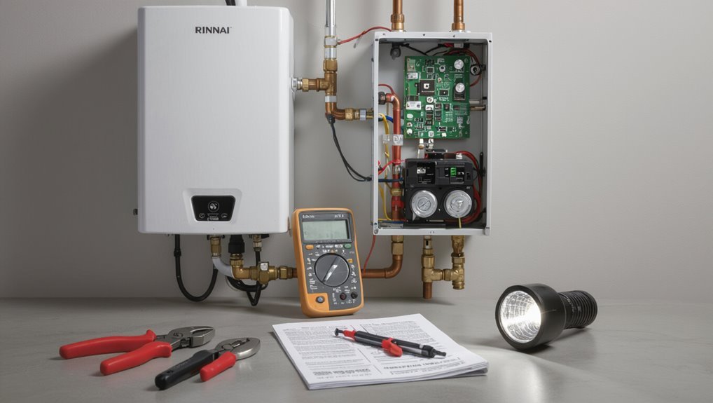
Rinnai Code 11 indicates an ignition failure or flame loss that prevents the heater from maintaining a stable burner flame. This code appears on many Rinnai tankless models and may be shown as “11,” “Err 11,” or a similar fault indicator depending on the unit and remote display.
Typical symptoms include repeated shutdowns, failure to produce hot water, extended ignition attempts, and error lights or beeps.
Direct explanation of Code 11 and its implications
Code 11 signals a flame failure in the tankless water heater’s ignition sequence, meaning the burner attempted to light but the system did not detect a sustained flame.
This fault halts heating and indicates ignition, fuel, or combustion-air issues.
Troubleshooting focuses on safe diagnosis: inspect gas supply, venting, flame sensor and ignition components; see how to fix rinnai code 11 before calling a technician.
Which Rinnai models use Code 11 and variant displays
Many tankless units across Rinnai’s lineup will flag a flame-failure event as an 11-type fault, but display formats and model-specific behaviors vary.
Older wall-hung units (RE, RUR series) and newer condensing models (RUC, EX series) may show “11,” “E11,” or segmented codes on remote controllers.
Digital panels, wireless remotes, and integrated diagnostics differ; consult model-specific manuals for exact code presentation.
Common symptoms associated with Code 11
Although the fault specifically signals flame failure, it typically presents through a few consistent symptoms that point to ignition or combustion interruptions.
Users often notice no hot water or intermittent heating, repeated ignition attempts with clicking, error LED or display Code 11, unusual odors or soot, and unit lockouts requiring manual reset.
Performance drops during high demand also occur.
Safety Precautions Before Troubleshooting
Before attempting any repair, the technician should gather required tools and materials and confirm the correct replacement parts.
The unit must be safely shut down and both electrical power and gas supply isolated according to the manufacturer’s instructions.
If the fault persists, combustion smells are present, or the technician is unsure at any step, service should be stopped and a licensed professional contacted.
Tools and materials needed
A small set of basic tools and safety items is required to diagnose and address a Rinnai Code 11 fault safely.
Recommended items: insulated screwdrivers, multimeter, flashlight, wrench set, soft brush, replacement O-rings and sensors, thread sealant, and a non-contact voltage tester.
Personal protective equipment: safety glasses, mechanic gloves, and a dust mask.
Keep manufacturer documentation and a camera for reference.
How to safely shut down the unit and isolate power/gas
Power down the Rinnai unit and secure all energy sources before any inspection or repair begins.
The technician isolates electrical supply at the breaker and confirms zero voltage with a meter.
Close the gas shutoff valve on the appliance supply line and verify no odor or pressure.
Wait several minutes for residual gas to dissipate.
Tag the controls and notify household occupants.
When to stop and call a professional
When should troubleshooting stop and a licensed technician be called?
If ignition attempts fail repeatedly, gas odor is present, water leaks occur, error codes persist after basic resets, or safety devices trip, cease DIY work.
Complex internal repairs, combustion issues, flammable smells, or uncertainty about gas lines require immediate professional service.
Contact a licensed technician to diagnose and repair safely.
Quick Restart Steps to Try First
A brief power reset is often the simplest first step: the unit should be turned off via the control panel or by switching the dedicated breaker, then left without power for 30–60 seconds before being restored.
When choosing between the control panel and breaker, the manual-off via panel is preferred for a controlled restart, while the breaker can be used if the panel is unresponsive.
After power is restored, observe the unit for correct ignition and any recurring error codes for at least several minutes to confirm whether the issue cleared.
How to perform a safe power reset
Begin by switching the Rinnai unit off at its dedicated circuit breaker or service switch to cut electrical supply safely.
Wait one minute to allow internal capacitors to discharge.
Turn off any external gas supply if recommended by the manual.
After waiting, restore the breaker or service switch, then observe startup behavior and error codes.
Document results and proceed with further diagnostics if Code 11 persists.
Resetting the unit through the control panel vs. breaker
Compare the two restart methods before choosing one: using the unit’s control panel offers a targeted, software-level reset that preserves electrical isolation and may clear transient faults.
On the other hand, cutting power at the breaker forces a full hardware reboot that can discharge capacitors and reset peripheral modules.
The control-panel reset is quicker and less intrusive; breaker cycling is deeper but requires ensuring the unit is fully de-energized.
What to observe after restart and timing expectations
Once power is restored, observe the unit for at least five minutes to note startup behavior, error codes, and any unusual sounds or smells.
Expect normal ignition within seconds, blower and burner sequencing, and steady LED or display status.
If Code 11 reappears immediately or within minutes, record timing and conditions, then proceed to diagnostics or contact certified service.
Step-by-Step Diagnostic Checklist for Code 11
A concise diagnostic checklist guides the technician through the most likely causes of Code 11, prioritizing verifiable readings and safety checks.
It begins with logged error patterns and power quality, then moves to gas delivery and combustion systems, and finishes with water flow and connections. Following a clear sequence reduces unnecessary parts replacement and speeds repair.
- Check error log and exact error pattern; confirm timestamps and repeatability
- Inspect power supply and voltage stability; verify gas supply and gas valve operation
- Examine water flow and inlet/outlet connections; inspect ignition system and flame sensing components
Check error log and exact error pattern
Where did the Code 11 originate and how often does it recur? The technician examines the unit’s error log, noting timestamps, frequency, and accompanying codes or lockouts.
Patterns—sporadic versus repetitive—indicate transient faults or persistent failures. Correlating events with user activity or environmental factors narrows causes.
Accurate logging guides targeted testing and determines whether firmware updates or component replacement are warranted.
Inspect power supply and voltage stability
Several quick checks establish whether the unit’s power feed is the source of Code 11: verify incoming AC voltage at the service disconnect, confirm stable DC voltage on the control board, and inspect wiring and connections for looseness, corrosion, or thermal damage.
Measure under load, compare readings to service specifications, tighten terminals, replace compromised leads, and retest to guarantee voltage remains within acceptable tolerance.
Verify gas supply and gas valve operation
Begin by confirming that the gas supply to the unit is present, clean, and pressurized to the manufacturer’s specification before testing valve function.
Next, isolate and visually inspect the gas valve and lines for leaks, corrosion, or blockages.
Measure inlet and outlet gas pressures, verify solenoid activation and continuity, and confirm valve seats and diaphragms operate smoothly per service manual.
Examine water flow and inlet/outlet connections
With gas supply and valve operation confirmed, attention moves to the water side: inspect inlet and outlet connections, flow restrictions, and sensor interfaces that can trigger Code 11.
Check for loose fittings, cross‑threading, scale buildup, clogged screens, and kinked supply lines.
Verify proper flow rate and pressure, validate check valves/openings function, and confirm temperature sensors and flow switches are secure and unobstructed.
Inspect ignition system and flame sensing components
Inspect the ignition and flame sensing components methodically to isolate faults that can produce Code 11.
Technicians should power down, verify electrode condition and gap, clean or replace corroded igniters, and confirm secure wiring and connectors.
Check flame rod cleanliness and position, test continuity and resistance values, and confirm proper grounding.
Reassemble and cycle unit to verify ignition sequence and flame detection.
Check venting and exhaust for obstructions
After verifying ignition and flame-sensing components, the technician should move on to the venting and exhaust path, since blockages or restrictions can prevent proper combustion airflow and trigger Code 11.
Inspect intake and exhaust terminals, roof penetrations, and horizontal runs for debris, bird nests, or crushed ducting.
Confirm proper slope, seals, and clearances; remove obstructions and test for unobstructed airflow before reattempting ignition.
Verify temperature sensors and thermistors
Verify the temperature sensors and thermistors next, since faulty readings can falsely signal flame loss or overheat conditions that produce Code 11.
Inspect sensor placement and physical condition, compare resistance to manufacturer specifications, and test continuity with a multimeter.
Replace any sensor outside tolerance.
After replacement, reset the unit and observe operation to confirm stable temperature feedback and elimination of the fault code.
Look for wiring damage, loose connectors, or corrosion
With sensors and thermistors checked, attention turns to the wiring harness and terminations that carry those signals. Damaged conductors, loose connectors, or corroded contacts can introduce intermittent or incorrect readings that mimic flame or overheat faults.
Inspect insulation for cuts, pinch points, or rodent damage. Wiggle connectors under power to reveal intermittent faults.
Clean corroded terminals with contact cleaner, tighten secure fittings, and replace compromised wiring.
Test control board and replace if necessary
Begin by isolating the control board as the next logical suspect when sensors, wiring, and connectors check out but Code 11 persists. A faulty board can fail to interpret flame or temperature inputs or misdrive outputs, producing the same symptoms as sensor or wiring faults.
Verify board voltages, signal continuity, and relay/transistor function per manual. Replace the PCB if diagnostics show intermittent faults or component failure.
Detailed Procedures for Common Causes
The following section outlines concise, actionable procedures for the most frequent triggers of Code 11: ignition or flame failure, inadequate gas pressure or supply, venting and condensate obstructions, faulty thermistors or temperature sensors, and control board faults.
Each cause is paired with step-by-step checks and recommended repairs or part replacements, including when to call a qualified technician.
Safety precautions and diagnostic tips are emphasized to guarantee accurate identification and secure corrective action.
Fixing ignition or flame failure
Diagnose ignition or flame failure by systematically checking the most common causes—gas supply, ignition spark, flame sensor, and venting—before replacing parts.
Inspect electrode gap and wiring for corrosion or looseness; clean or adjust electrodes.
Clean the flame sensor with fine abrasive and reinstall.
Verify exhaust venting is clear and draft correct.
Replace faulty igniter or sensor only after testing.
Resolving insufficient gas pressure or supply issues
Check gas pressure and supply continuity first, since inadequate flow is a frequent cause of Code 11; this involves measuring inlet and manifold pressures, confirming gas meter and regulator function, and ensuring shutoff valves and fittings are fully open and leak‑free.
If pressures fall outside specifications, inspect upstream piping for restrictions, test for slow leaks, verify correct supply sizing, and coordinate corrections with the gas utility or a certified technician.
Clearing vent blockages and condensate issues
Several straightforward inspections can quickly identify vent obstructions and condensate problems that trigger Code 11.
Inspect intake and exhaust terminations for debris, nests, or ice; clear blockages with flexible brushes or compressed air.
Check condensate drain and trap for clogs or freezing; flush with warm water and replace damaged tubing.
Verify proper slope and secure fittings to prevent recurrence.
Replacing faulty thermistors or temperature sensors
Begin by isolating the unit and cutting power at the breaker to guarantee safety before handling any sensors.
Technicians should access the panel, locate thermistors per schematic, document wiring positions, then disconnect and test resistance values against manufacturer specs.
Replace any out-of-range sensor with OEM parts, secure connectors, restore panels, reapply power, and verify proper temperature readings and error-code clearance.
Repairing or replacing the control board
If replacing thermistors did not clear Code 11, attention should turn to the control board, a frequent source of intermittent ignition and flame-sensing faults.
Inspect for burn marks, swollen components, or loose connectors.
Verify voltage and signal continuity per service manual.
Replace the board with OEM parts if diagnostics indicate failure, document configuration settings, and test multiple ignition cycles to confirm resolution.
Addressing water flow restrictions and scale buildup
Inspect the unit for signs of restricted flow and mineral buildup, since scale and debris are common causes of low water circulation that trigger Code 11.
Flush cold-water inlet, clean filter screens, and descale heat exchanger per manufacturer instructions.
Check faucets, flow sensors, and plumbing for obstructions.
Restore proper flow, verify sensor operation, and retest.
Recommend periodic maintenance or water-softening to prevent recurrence.
Diagnostic Tests and Measurements
Technicians proceed with targeted diagnostic tests and measurements to isolate the cause of a Rinnai Code 11 fault.
They verify gas pressure and electrical parameters, confirm thermistor resistance, and use temperature or combustion tools where needed. Results are compared to manufacturer specifications before any component replacement.
- Measure gas pressure and confirm it is within acceptable range.
- Perform electrical checks: voltage, continuity, and proper grounding.
- Test thermistor resistance and use a combustion analyzer or infrared thermometer for temperature verification.
How to measure gas pressure and acceptable ranges
Measuring gas pressure requires a few specific tools—manometer or digital gauge, appropriate fittings, and a regulator adapter—and a clear procedure to obtain accurate inlet and manifold readings.
Technicians isolate the supply, connect the gauge at the appliance test port, record static inlet pressure, then run the unit to note manifold (operating) pressure.
Acceptable ranges: natural gas inlet 6–8″ WC, manifold ~3.5–4″ WC; propane ~11–13″ WC.
Electrical tests: voltage, continuity, and grounding
Begin by verifying the electrical integrity of the water heater with three basic tests: voltage, continuity, and grounding.
Measure supply voltage at terminals, confirming correct nominal values and stable readings under load.
Check continuity across connectors, harnesses, and safety switches for open circuits.
Verify chassis-to-earth resistance is low and bonding is secure.
Record results and compare to manufacturer tolerances.
How to test thermistor resistance and expected values
To test the thermistor, isolate the heater, disconnect the sensor from the control board, and measure its resistance with a calibrated digital multimeter at room temperature.
Compare the reading to the manufacturer’s specified nominal value and temperature-resistance curve to determine if the sensor is within tolerance.
Typical Rinnai inlet thermistors read about 10 kΩ at 25°C, decreasing with rising temperature; replace if outside tolerance.
Using a combustion analyzer or infrared thermometer
After verifying thermistor values, the next step is to assess combustion and surface temperatures using a combustion analyzer or an infrared thermometer to confirm safe, efficient operation.
The technician should measure CO, O2, and flue temperature with a combustion analyzer to verify proper combustion.
Use an infrared thermometer to spot abnormal heat on the heat exchanger or venting.
Record readings and compare to manufacturer specifications.
When to Replace Parts vs Replace the Unit
The discussion weighs repair options by comparing the cost and remaining lifespan of a control board versus replacement.
It notes that sensors and valves are typically replaced when failures are isolated and parts are affordable relative to expected service life.
It also outlines clear signs—recurrent faults, extensive corrosion, or high cumulative repair costs—when replacing the entire unit is more economical.
Cost and lifespan considerations for control board replacement
When evaluating whether to replace a Rinnai control board or retire the entire unit, owners should weigh replacement cost, remaining appliance lifespan, and the likelihood of future failures.
Consider parts and labor estimates versus typical tankless longevity (10–15 years), recent repair history, and warranty coverage.
If cumulative repairs approach new-unit cost or the unit nears end-of-life, replacement is often more economical and reliable.
When sensor or valve replacement is appropriate
If a Rinnai tankless shows recurring Code 11 errors tied to flow or temperature inconsistencies, owners should determine whether individual sensors or valves are the root cause before committing to full-unit replacement.
Replacement is appropriate when diagnostics isolate a faulty flow sensor, temperature probe, or diverter valve, when parts are available and affordable, and when installation restores stable readings without further systemic errors.
Signs that indicate full unit replacement is more economical
After determining that individual sensors or a valve are not the sole causes of repeated Code 11 faults, owners should evaluate whether replacing the entire Rinnai unit is more cost-effective than swapping multiple components.
Indicators include frequent failures across systems, high cumulative repair costs approaching replacement value, discontinued parts, extensive corrosion or water damage, and unreliable performance after prior repairs.
Preventive Maintenance to Avoid Code 11 Recurrence
Preventive maintenance reduces the likelihood of Code 11 by addressing common causes before they escalate. A concise routine combining homeowner checks and periodic professional service helps maintain reliability and efficiency.
The following priorities should be included in any maintenance plan:
- Regular inspection schedule with seasonal checks and recommended professional service intervals
- Flushing and descaling procedures to prevent buildup
- Keeping vents and condensate drains clear
Regular inspection schedule and seasonal checks
A regular inspection schedule, tailored to usage intensity and local climate, reduces the likelihood of Rinnai Code 11 by catching worn components, venting issues, and condensation-related faults before they escalate.
Monthly visual checks, quarterly combustion and vent inspections, and pre-winter assessments for cold climates guarantee seals, sensors, and exhaust paths remain sound.
Document findings and schedule repairs promptly to prevent recurrence.
Flushing and descaling procedures
Flushes and descaling cycles remove mineral buildup and sediment that impair heat exchange and exhaust flow, both common contributors to Rinnai Code 11.
Technicians should follow manufacturer procedures: isolate water, connect pump and descaling solution, circulate for recommended duration, then flush thoroughly with clean water.
Repeat annually or more often in hard-water areas. Record chemicals used, concentrations, and service dates for warranty and diagnostics.
Keeping vents and condensate drains clear
Regular inspections of vents and condensate drains minimize the risk of blockages that can trigger Rinnai Code 11.
Technicians should clear debris, bird nests, and scale from exhaust and intake vents, and flush condensate lines to prevent buildup.
Guarantee proper pitch and trap integrity so condensate drains freely.
Record findings and corrective actions to monitor recurring issues and verify long‑term operation.
Recommended professional service intervals
For proactive prevention of Code 11 recurrence, technicians should schedule professional inspections and maintenance at defined intervals tailored to system age, usage, and water quality.
Recommended cadence: annual thorough service for newer units, biannual checks for high-demand or hard-water installations, and immediate evaluation after fault history.
Services should include combustion analysis, condensate system inspection, vent integrity checks, and preventive component replacement as needed.
Example Troubleshooting Scenarios and Solutions
The following examples present common Code 11 situations with clear step-by-step remedies.
Each scenario highlights typical causes and practical checks that a technician or homeowner can perform safely. Brief solutions focus on ignition, demand-related faults, and cold-weather impacts.
- Scenario: Unit fails to ignite after power outage — stepwise fix
- Scenario: Intermittent Code 11 only during peak demand — stepwise fix
- Scenario: Code 11 after freeze or cold weather — stepwise fix
Scenario: Unit fails to ignite after power outage stepwise fix
After a power outage, a Rinnai unit that displays Code 11 and refuses to ignite often needs a systematic restart and verification of electrical and gas inputs before further diagnostics.
The technician should reset power at breaker, cycle the unit per manual, confirm battery backup if present, verify gas supply and valve position, inspect venting and ignition components visually, and log results before pursuing component replacement.
Scenario: Intermittent Code 11 only during peak demand stepwise fix
When intermittent Code 11 appears only during peak demand periods, the technician shifts focus from simple restart and supply checks to load-related causes and transient conditions.
They inspect inlet pressure under load, verify gas meter and regulator performance, check venting for flow restrictions, and monitor combustion stability with a manometer.
Recommended fixes include pressure regulator replacement, adding demand balancing, or installing a pressure regulator with better transient response.
Scenario: Code 11 after freeze or cold weather stepwise fix
Because freezing temperatures can introduce moisture, ice, and brittle components, a Code 11 appearing after cold weather signals likely obstruction or impaired gas flow and sensor malfunction from freeze-related damage.
Inspect venting and condensate lines for ice, thaw safely, check gas inlet and fittings for blockage or leaks, verify flame rod/sensor condition, replace brittle tubing, and restart unit.
Seek professional service if persistent.
Parts, Costs, and Where to Get Replacements
The section outlines common replacement parts, typical price ranges, and the trade-offs between OEM and aftermarket options for resolving Code 11. It also explains how to locate the correct part numbers for a specific Rinnai model. The brief table below summarizes typical parts and cost expectations.
| Part / Topic | Typical Range or Note |
|---|---|
| Igniter, flame sensor, control board | $20–$350 depending on part |
| OEM vs aftermarket, finding part numbers | OEM offers fit assurance; use model/serial from unit for exact matches |
Common replacement parts, typical price ranges, and OEM vs aftermarket notes
Identify the most frequently replaced components for a Rinnai unit—ignition board, thermistor/temperature sensor, flame rod/igniter, and gas valve—and outline typical price ranges and sourcing options.
Typical costs:
- ignition board $60–$250
- thermistor $15–$60
- flame rod/igniter $10–$80
- gas valve $150–$600
OEM parts cost more; aftermarket alternatives are cheaper but vary in reliability.
Authorized dealers, online retailers, and HVAC suppliers are common sources.
How to find correct part numbers for your Rinnai model
After covering which parts commonly fail and typical price ranges, locating the exact part number for a Rinnai unit is the next step to guarantee a proper match.
Check the model/serial plate on the unit, consult the owner manual or Rinnai parts lookup online, and cross-reference OEM numbers with authorized dealers.
Confirm compatibility before purchase; save receipts and part documentation.
When to Call Rinnai Support or a Licensed Technician
Before contacting Rinnai support or hiring a licensed technician, gather the model and serial numbers, the exact Code 11 readout, recent error logs, and a brief history of troubleshooting steps already taken.
The caller should also confirm technician credentials by asking for license numbers, proof of insurance, and Rinnai certification where applicable.
Warranty status and whether repairs or parts replacements are covered should be verified prior to authorizing any paid work.
What information and error logs to provide before calling
When contacting Rinnai support or a licensed technician about a Code 11, they should be given a concise packet of details:
- model and serial numbers,
- installation date,
- recent service history,
- exact error code sequence and timestamps,
- flame or ignition behavior,
- gas/electric supply status,
- water pressure readings,
- steps already attempted,
- photos or short video of the unit and error display,
- and any relevant environmental changes.
How to verify technician credentials and warranty considerations
With the diagnostic packet prepared, the next step is to confirm that any technician engaged is properly credentialed and that service actions will not void remaining warranty coverage.
Verify licensing, Rinnai-authorized dealer status, and insurance; request identification and written estimates.
Check warranty terms for authorized service requirements and claim procedures.
Contact Rinnai support with serial/model and diagnostic details before authorizing repairs.
Closing Checklist Before Restarting Service
Before restoring full operation, a technician completes final safety and functionality checks to confirm combustion, venting, and controls are normal.
All repairs and tests are logged with timestamps, parts used, and any deviations from standard procedures.
A follow-up maintenance appointment is scheduled if needed to verify long-term performance.
Final safety and functionality checks
Complete a systematic closing checklist to verify the appliance is safe and fully functional prior to returning it to service.
Verify combustion air and vent paths are clear, gas connections are leak-free, and ignition cycles operate normally.
Confirm water temperature, pressure, and flow meet specifications.
Inspect for error codes, secure panels, and guarantee all safety devices (pressure relief, flame sensor) respond correctly before restoring regular use.
Logging work done and scheduling follow-up maintenance
Having confirmed safety systems and operational parameters, the technician documents all actions taken, components replaced, test results, and any anomalies observed in the service record.
The entry includes date, time, serial numbers, and measured values. Recommendations for parts, warranty notes, and client instructions are recorded.
A follow-up service is scheduled based on manufacturer intervals or observed wear, with reminders set and customer notified.
Conclusion
A brief investigation into the Code 11 theory reveals it most often signals an ignition failure rather than a mysterious system collapse. The technician notes that simple resets or blocked air/fuel issues commonly resolve the fault. While occasional component replacement is required, empirical steps—safe shutdown, inspection, restart—regularly restore operation. If uncertainty or persistent errors remain, Rinnai support or a licensed technician should be engaged to confirm diagnosis and complete repairs.