How to Install a Vent Pipe: Step-by-Step DIY Guide for Homeowners
To install a vent pipe successfully, first verify local codes and permits, then select the appropriate vent material (PVC, ABS, or metal) and size based on fixture units. Plan a direct and short route through wall cavities and the roof, minimizing offsets. Mark and cut the necessary openings, then assemble and support the pipe securely with proper straps. Ensure to flash and seal the roof penetration correctly according to your roof type, and finally, conduct pressure and airflow tests. This step-by-step guide also highlights common mistakes, potential costs, and advises when to consult a professional for more complex issues.
Which Vent Pipe Is Right for Your Home?
Choosing the right vent pipe depends on the home’s plumbing layout, local building codes, and the types of fixtures served.
The installer evaluates pipe material—PVC, ABS, or cast iron—based on durability, cost, and compatibility with existing lines.
Pipe diameter is chosen from fixture units; larger stacks or multiple fixtures require greater capacity.
Routing considers shortest, most direct paths to the roof while minimizing bends that impede airflow.
Roof penetration methods and flashing types are matched to roofing material to prevent leaks.
Proper slope and secure supports are specified to prevent sagging and make certain continuous ventilation for trap seals.
Check Local Codes and Permits
Before beginning work, the installer should verify permit requirements with the local building department.
Code specifications for vent pipe materials, sizing, and placement often vary by municipality and climate zone. Confirming these variations early avoids costly rework and potential violations.
Permit Requirements
Although plumbing projects may seem simple, installing a vent pipe often triggers local permitting requirements that must be confirmed before work begins.
Homeowners should contact the local building department to determine permit necessity, application procedures, fees, and required documentation.
Plans or simple drawings may be required showing pipe routing, materials, and roof penetrations.
Inspections are commonly mandated at rough-in and final stages; scheduling, access, and correction procedures must be understood.
Failure to obtain permits can result in fines, forced removal, or complications when selling the property.
When uncertain, consult a licensed plumber or the authority having jurisdiction for authoritative guidance.
Code Variations By Area
Across jurisdictions, vent pipe requirements can differ substantially, so installers must verify local plumbing codes, amendments, and municipal ordinances before proceeding. Variations affect pipe size, slope, termination height, materials, and required inspections. Homeowners should consult municipal codebooks or building departments, obtain permits when required, and schedule official inspections to make certain compliance. Failure to follow local rules can lead to rework, fines, or unsafe systems. Professional consultation is advised for unclear cases. The following summary highlights common distinctions:
| Element | Common Variations |
|---|---|
| Size & Slope | Minimum diameters, maximum offsets |
| Termination | Roof height, clearance requirements |
Choose Vent Pipe Material and Diameter
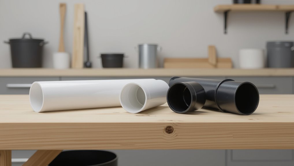
When selecting vent pipe material and diameter, the installer should balance durability, code requirements, and system capacity; common materials include PVC, ABS, copper, and cast iron, each with distinct corrosion, temperature, and stiffness characteristics that affect installation and longevity.
The installer evaluates fixture units and run length to determine required diameter—typically 1¼”–2″ for individual fixtures, larger for groups—to preserve trap seal integrity and prevent siphoning.
Compatibility with fittings, solvent or solder methods, thermal expansion, and roof penetration details influence choice.
Local code adoption may mandate specific materials or sizes; document selections before procurement and rough-in.
Tools, Fasteners, and Safety Gear Checklist
A concise list of required tools and appropriate safety gear follows to guarantee the vent pipe is installed correctly and safely.
Essential tools include a tape measure, pipe cutter, drill, sealant applicator, and appropriate fasteners for the chosen material.
Recommended safety gear comprises gloves, eye protection, a dust mask, and fall protection when working at height.
Tools Needed
Several essential tools, fasteners, and safety items are required to install a vent pipe safely and correctly.
A cordless drill with masonry and wood bits, reciprocating saw or hole saw sized to pipe diameter, adjustable wrench, pipe cutter, and tin snips are primary cutting and fastening tools.
A tape measure, level, chalk line, and marker assure alignment.
Fasteners include stainless steel screws, pipe straps, flashing, and appropriate sealant or roof cement.
A caulking gun and plumber’s tape complete joins.
Protective gloves, eye protection, and a dust mask are noted here but detailed under the dedicated safety section.
Safety Gear
Before putting tools and fasteners to use, the installer should verify personal protective equipment and site safeguards are in place. The installer inspects hard hat, eye protection, gloves, and respirator for fit and damage, confirms ladder stability, and makes certain work area is ventilated and clear. Fasteners are organized and matched to material; tools are checked for safety features and cord integrity. A concise checklist reduces omissions and accidents.
| Item | Purpose |
|---|---|
| Hard hat | Impact protection |
| Safety glasses | Eye protection |
| Gloves | Hand protection |
| Respirator | Dust/fume protection |
Plan the Vent Route Through Walls and Roof
Determine the most direct, code-compliant path for the vent that minimizes roof penetrations and avoids plumbing, electrical, and structural obstructions. Inspect attic and wall cavities to locate studs, joists, rafters, wiring, and HVAC ducts.
Use stud finders and inspection holes to trace a straight vertical route where possible; offset only when required by structure. Choose a routing that places wall penetrations away from windows and doors and on roof slopes that allow proper flashing installation.
Mark penetration points on both interior and exterior surfaces. Verify local code clearances to combustibles and neighboring vents before cutting or drilling.
Calculate Vent Rise, Slope, and Allowable Runs
When calculating vent rise, slope, and allowable runs, the installer must translate fixture unit loads and trap sizes into minimum vertical rise and maximum horizontal length per code tables, then apply required slope for proper drainage and condensate flow.
The technician cross-references local plumbing code charts to determine stack size and maximum developed length for each fixture group.
Vertical rise guarantees adequate air column to prevent trap siphonage; horizontal runs must not exceed specified limits without additional venting.
Required slope (typically 1/4″ per foot for drainage) and pitch for condensate lines are verified, and combined vents are sized accordingly.
Measure and Mark Cutting Points Accurately
Having established vent rise, slope, and allowable runs, the installer next measures and marks exact cutting points to translate those calculations into accurate pipe lengths.
The installer confirms each segment’s required length, adds coupling or fitting allowances, and notes orientation for offsets and inspection access.
Using a tape measure and carpenter’s pencil, marks are placed square to the pipe axis; a straightedge guarantees alignment across multiple pieces.
Measurements are double-checked against fittings and joint clearances.
For metal pipe, scribe lines align with cutting tools; for plastic, wrap marks with masking tape to prevent splintering.
Labels identify piece destination and orientation.
Cut Drywall and Roof Decking Safely
The installer marks exact cut locations on drywall and roof decking before any tooling begins.
Surrounding surfaces are protected with drop cloths and tape to prevent damage and debris spread.
Cuts are made with the appropriate blades and steady technique to guarantee safe, clean openings.
Mark Cut Locations
Begin by transferring the vent’s centerline and pipe diameter to the ceiling and roof deck using measurements from the vent flange; accurate, clearly marked reference lines prevent misalignment between interior and exterior cuts.
Verify alignment by measuring from fixed framing points and repeating dimensions on both sides of the roof slope.
Mark the cut outline for drywall with a pencil and for decking with a contrasting marker so lines remain visible in varied light.
Note joist and rafter locations to avoid structural members; shift the opening slightly if necessary.
Double‑check clearances for the flashing and pipe collar before cutting.
Protect Surrounding Surfaces
While cutting drywall and roof decking, workers should shield adjacent surfaces to prevent gouges, dust infiltration, and moisture damage by using protective barriers such as drop cloths, adhesive-backed foam, and rigid corner guards.
Seal openings with painter’s tape or removable plastic to contain dust.
Place sacrificial plywood under tools to prevent blade marks on flooring and deck sheathing.
Protect nearby insulation and electrical boxes with fitted covers.
Keep fastener heads and tool rests capped to avoid punctures.
Remove trim or molding and store safely.
Inspect barriers periodically during work and replace compromised pieces immediately to maintain continuous protection.
Cut Safely And Cleanly
After protective barriers are in place and inspected, cutting drywall and roof decking requires steady technique and the right tools to produce clean, safe openings for the vent pipe. Workers mark the hole using the vent template, verify clearances from studs and rafters, and probe cavities for wiring or plumbing.
A drywall saw or oscillating tool trims plasterboard; a circular saw with blade depth set or jigsaw cuts decking from above, avoiding roof shingles when possible. Cuts proceed slowly, supporting removed panels to prevent splintering. Debris is collected promptly, edges are sanded, and openings are checked for correct diameter and alignment.
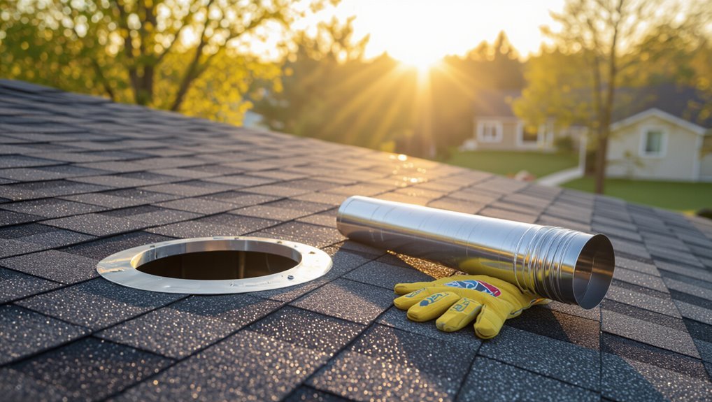
Install Roof Flashing and Boot After Cutting
With the pipe protruding through the roof, the installer fits the flashing base over the pipe and seats it flush against the shingles, ensuring the upper flap slips beneath the surrounding courses to shed water.
The flashing is aligned so its lower edge rests on exposed shingles, and fasteners are placed through predrilled holes into roof decking, avoiding nail contact with the pipe.
The rubber boot is slid down over the pipe and adjusted to sit snugly against flashing, trimmed if needed for a tight fit.
Excess material is removed, and fasteners are checked for security before proceeding.
Seal Roof Penetrations to Prevent Leaks
Attention turns to sealing around the flashing and collar to guarantee a waterproof roof penetration.
Proper sealant application technique—choosing compatible products, creating continuous beads, and tooling seams—secures the barrier against weather.
Careful inspection and neat workmanship prevent gaps that lead to leaks.
Flashing And Collar Installation
When a vent pipe penetrates a roof, properly installed flashing and a fitted collar form the primary waterproof barrier; they direct water away from the pipe and under surrounding shingles to prevent leaks.
Install step flashing under upper shingles and over lower shingles, bending to match roof pitch. Slide the base flashing around the pipe, make certain the flange sits flush, and fasten with corrosion‑resistant nails placed on flange high enough to shed water.
Fit a split or adjustable collar over the pipe, seating it inside the flashing throat. Trim excess pipe boot if necessary so the collar seals snugly without gaps.
Sealant Application Techniques
For effective long-term protection, sealant must be chosen and applied to create a continuous, flexible barrier between flashing, collar and pipe without interfering with shingles or roof drainage. The installer inspects surfaces, cleans debris, and primes if manufacturer recommends. A consistent bead is applied where collar meets pipe and along flashing edges; tooling smooths and forces sealant into gaps. Excess is wiped; curing time is observed before re-roof traffic. Compatibility with roofing materials and UV resistance are verified. Periodic inspection and touch-up prevent leaks. Tools and materials are kept minimal and appropriate for neat, durable seals.
| Item | Purpose |
|---|---|
| Sealant type | Flexibility, adhesion |
| Primer | Improve bond |
| Caulking gun | Even bead |
| Tooling spatula | Smooth finish |
Assemble and Join Vent Pipe Sections
Beginning at the roof penetration and working downward, assembling and joining vent pipe sections requires correct alignment, secure connections, and proper sealing to maintain system integrity.
Each section is fitted male-to-female, slid fully home, and rotated to align seams. Apply approved sealant or gasket at joints per manufacturer instructions before final engagement. Tighten any clamp bands or threaded couplings evenly to avoid distortion.
Inspect each joint visually and by hand for gaps, ensuring proper overlap and continuity of slope where required.
Clean burrs and debris from cut ends prior to joining to prevent leaks and blockages.
Support and Strap Vertical Vent Pipe Runs
Proper support is essential for vertical vent pipe runs, beginning with strap spacing guidelines to prevent sagging and joint stress.
The paragraph briefly contrasts common support types—pipe straps, clamps, and hangers—and notes material and load considerations.
It also emphasizes secure anchoring to the structure to transfer loads and limit movement.
Strap Spacing Guidelines
Typically, vertical vent pipes require support straps at regular intervals to prevent sagging, misalignment, and undue stress on joints. Guidelines vary by pipe material and diameter: smaller PVC may need straps every 4–6 feet, larger metal pipes every 6–8 feet. Straps should be placed near joints and at top and bottom runs. Avoid overtightening; allow slight movement for thermal expansion. Inspect straps for corrosion and secure to structural members only. Follow local code for maximum spacing.
| Pipe Type | Diameter Range | Typical Spacing |
|---|---|---|
| PVC | 1–2 in | 4–6 ft |
| Metal | 2–4 in | 6–8 ft |
Support Types Explained
When supporting vertical vent pipe runs, several strap and hanger types are used to maintain alignment, control movement, and distribute load without restricting thermal expansion.
Metal band straps secure pipe to framing, offering firm lateral restraint while allowing slight axial movement when slotted or fitted with neoprene.
Saddle clamps cradle pipe at intervals, distributing weight to hangers or ledgers.
Clevis hangers permit vertical adjustment and isolate vibration.
Split-ring hangers accommodate insulation and protect finishes.
Adjustable pipe supports provide precise elevation control near changes in condition.
Selection depends on pipe material, diameter, temperature, and code requirements; proper choice prevents sagging and undue stress.
Anchoring To Structure
Having selected appropriate straps and hangers, attention turns to anchoring the vertical vent run to the building structure to control lateral loads, prevent displacement, and permit specified axial movement.
Install supports at code-prescribed intervals, fastening to studs, joists, or masonry with corrosion-resistant anchors. Allow slip joints or sliding brackets where thermal expansion is expected; secure only at designated anchor points to avoid stressing the system. Use vibration-isolating pads where mechanical noise may transmit. Verify alignment plumb and level, tightening fasteners to manufacturer torque.
Inspect penetrations and seal around pipe with fire- and weather-rated materials per local codes before final testing.
Run Vent Pipe Through Attic or Crawl Space
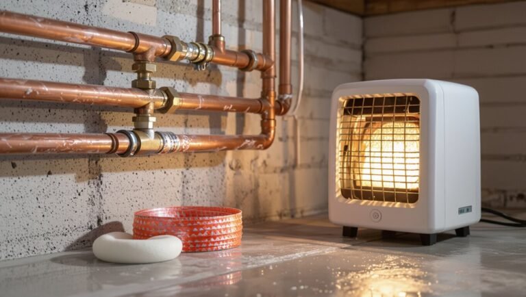
In confined spaces such as attics or crawl spaces, routing a vent pipe requires attention to slope, support, and thermal concerns to maintain proper drainage and prevent condensation or freezing. The installer measures a straight run, keeps a 1/4″ per foot slope where required, and secures the pipe with straps every 4–6 feet. Insulation or heat tracing is added in cold areas. Penetrations through fire-rated assemblies use appropriate collars and sealing. Access panels are planned for future inspection.
| Item | Purpose |
|---|---|
| Slope | Drainage |
| Supports | Stability |
| Insulation | Prevent freezing |
| Seals | Fire/air barrier |
Tie Into Existing Plumbing Stacks
The installer first identifies the main stack location to determine the appropriate connection point.
They follow local tie-in height rules to guarantee proper venting and prevent siphoning.
After making the connection, the joint is sealed and the system is pressure-tested for leaks.
Locate Main Stack
A main soil stack serves as the backbone for venting and waste removal, so locating it accurately is essential before tying a new vent into existing plumbing stacks.
Identify the stack by tracing visible pipe runs in basements, crawlspaces, or utility rooms; follow vertical cast-iron or PVC lines from fixtures to the roof.
Use access panels, cleanouts, and building plans to confirm position.
Mark stack location on framing and underside of joists, noting nearby obstructions and structural members.
Verify material changes and connection points for compatibility.
Document measurements and photographs to guide routing and prevent interference during vent tie-in.
Tie-In Height Rules
Ensuring proper tie-in height prevents trap siphonage, backflow, and venting inefficiencies when connecting a new vent to an existing plumbing stack.
The new vent must join the stack above the highest fixture’s flood level rim it serves, typically at least 6 inches higher, to maintain air passage and prevent sewage entry.
For multi-story systems, tie-ins occur above the branch drain connection serving the same fixtures to avoid interference.
Local codes dictate minimum distances and offsets from cleanouts and other vents; follow manufacturer and code tables for diameters and heights.
Verify slope, alignment, and secure support to avoid stress on joints.
Seal And Test
After the new vent is tied into the stack at the proper height, attention turns to sealing and testing the connection to confirm integrity and code compliance.
The joint is cleaned, fluxed or primed as required, and fitted with the correct couplings, solvent welds, or mechanical seals.
External flashings and roof penetrations are resealed with compatible, weatherproof materials.
A pressure test follows: cap the vent, introduce water or air to specified test pressure, and monitor for leaks for the required duration.
Any leak is located, repaired, and retested.
Documentation of results and inspection by authorities completes the process.
Install a Vent Cap and Rain Screen Correctly
How should the vent cap and rain screen be fitted to prevent water entry while preserving airflow? The vent cap must align flush with the pipe, using a gasket or silicone sealant to block leaks while avoiding obstruction of the outlet.
The rain screen—a perforated or louvered sleeve—should surround the cap, fastened to the exterior with corrosion-resistant screws and sealed at its base to shed water. Assure clearances for airflow and rodent screens that do not clog.
Verify cap orientation per manufacturer instructions and trim excess material. Regularly inspect and clear debris to maintain function and prevent moisture intrusion.
Test Vent Airflow and Pressure After Installation
Begin testing the vent system by measuring airflow and static pressure to confirm the installation performs to specifications. A technician uses an anemometer at the vent outlet and a manometer at accessible test ports to record cubic feet per minute (CFM) and inches of water column (in. w.c.). Compare readings to design values or appliance manufacturer requirements. Verify consistent flow across operating ranges and note any unexpected pressure drops indicating restrictions. Repeat measurements after a short run period to detect thermal or condensation effects. Document results, include instrument calibration references, and retain data for future maintenance or warranty claims.
Troubleshoot Common Vent Pipe Problems and Noises
Identify the source and character of the problem before making repairs: common vent pipe issues include blockages, improper slope, loose joints, condensate accumulation, and insufficient draft, each producing distinct symptoms such as reduced flow, gurgling, whistling, or banging.
A methodical approach isolates causes and selects corrective actions: inspect lines, listen at fittings, and check slope and traps. Recommended responses address specific faults.
- Clear blockages with a snake or compressed air.
- Re-establish correct slope and support brackets.
- Tighten or reseal loose joints; replace damaged sections.
- Drain condensate and add traps or insulation to prevent recurrence.
Annual Inspection and Maintenance Checklist
Regularly, a concise annual inspection and maintenance checklist guarantees vent pipes remain safe and functional by identifying wear, blockages, and alignment issues before they cause failures. Inspect flashing, seals, and pipe condition; clear debris and nests; test airflow with a smoke source; tighten loose straps; and note corrosion or cracks for prompt repair. Record findings, dates, and actions in a log. Schedule professional assessment if ventilation remains poor or damage is extensive. Use the checklist to prioritize repairs and prolong system life.
| Item inspected | Action required |
|---|---|
| Flashing | Check seal |
| Pipe | Inspect corrosion |
| Straps | Tighten |
| Opening | Clear debris |
| Airflow | Test |
Vent Penetrations: Shingle, Metal, and Flat Roofs
After completing the annual checklist, attention turns to how vent pipes pass through different roof types, since flashing, sealants, and attachment methods vary with materials and slope. Guidance outlines appropriate penetrations for common roofs, emphasizing compatibility and weatherproofing.
- Shingle roofs: use a rubber boot with metal flange, tuck under shingles above the pipe, seal lower edge with compatible roofing cement.
- Metal roofs: select a low-profile flashing sized for rib geometry, secure with neoprene washers and non-corrosive fasteners, seal seams with approved sealant.
- Flat roofs: employ a raised curb or prefabricated roof drain-style flashing, use membrane-compatible adhesive.
- Inspect for proper slope and drainage around penetration.
Common DIY Mistakes That Cause Leaks or Blockages
Often homeowners underestimate how small installation errors compound into leaks or blockages; common DIY mistakes include improper sealing, wrong flashing selection, insufficient slope, and tight bends that trap debris.
Inadequate sealant bead or poorly seated gaskets let water infiltrate roof and chase onto sheathing.
Flashing sized or shaped incorrectly fails to shed runoff at roof pitches.
Pipes set without a slight downward exterior pitch collect condensation and waste, inviting clogs.
Excessive or sharp elbows increase turbulence and snag solids.
Loose fasteners, mismatched materials causing corrosion, and neglected vent caps similarly shorten service life and raise leak or blockage risk.
When to Call a Pro: Red Flags and Safety Limits
Small installation errors can quickly escalate into dangerous conditions or costly repairs, and there are clear signs that a professional should be engaged instead of continuing as a DIY project. When uncertain, stopping prevents harm.
Key red flags include:
- Structural compromises such as cutting load-bearing rafters or unclear roof framing that risks leaks or collapse.
- Persistent sewer gas smells or recurring backpressure indicating venting or sewer line issues beyond basic fixes.
- Complex roof flashing, multiple penetrations, or working on steep or high roofs that require safety harnesses and experience.
- Local code confusion, permit requirements, or inspections where compliance decisions are necessary.
Typical Time and Cost Breakdown for a Vent Install
A typical residential vent installation takes between two and six hours for a single fixture when performed by a skilled plumber or qualified DIYer. Time varies with access, roof penetration, routing, and permit work.
Labor rates range widely; expect $150–$600 for pro labor in many regions. Material costs for pipe, fittings, flashings, and sealants typically add $30–$200.
Complex jobs (multiple fixtures, long runs, roof work, or attic insulation) raise hours and may require $500–$1,500 total. Permit fees and unexpected repairs (rotted decking, code corrections) increase expense; obtaining multiple quotes reduces cost uncertainty and scope surprises.
Conclusion
Homeowners can install vent pipes safely by following code, choosing proper materials, and using correct flashing techniques, yet some worry they lack skill. This guide shows the steps and precautions to prevent leaks and blockages; with patience and the right tools, success is achievable. If complexity or height feels overwhelming, that concern is valid — hiring a pro protects investment and safety, turning anxiety into relief and confidence in the outcome.