How to Test Hydrostatic Pressure: Step-by-Step Methods for Accurate Results
To conduct a hydrostatic pressure test, isolate the fluid-filled section, fill it with water, and pressurize it to a specified target while monitoring for leaks. Technicians should attach calibrated gauges, purge air, gradually increase pressure, stabilize for thermal effects, and maintain the pressure for a designated period, logging readings and observations. If any failures occur, repairs and retesting are necessary. Documentation should include dates, personnel involved, and corrective actions taken. Adhering to safety protocols and standards is essential for reliable results, and understanding procedural variations and troubleshooting methods can enhance testing accuracy.
What Hydrostatic Pressure Is and Why Accurate Testing Matters
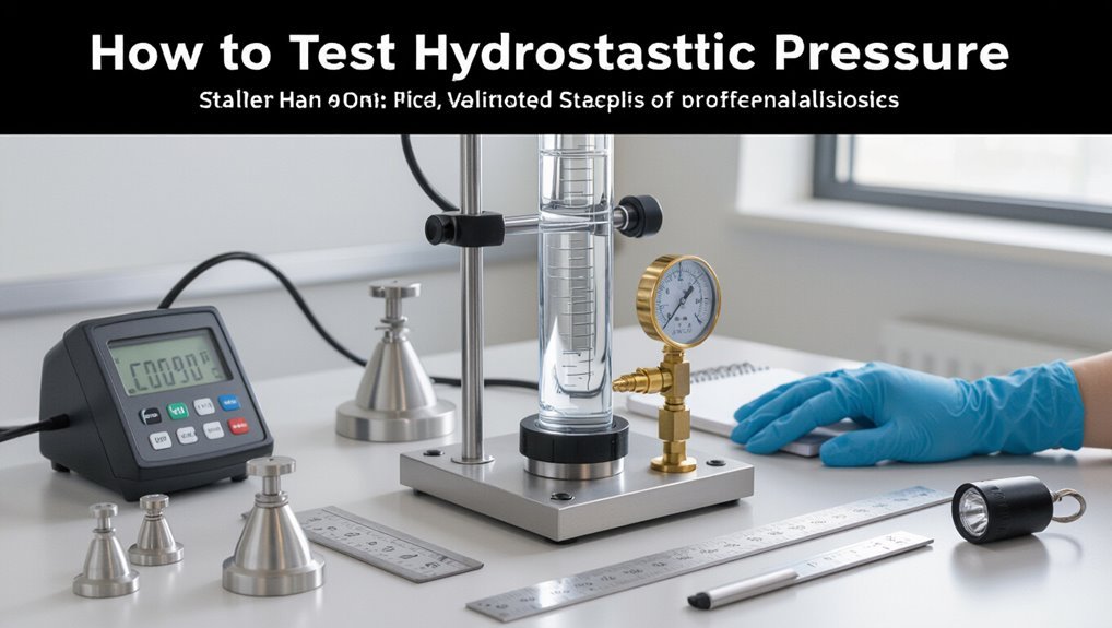
Hydrostatic pressure is the force exerted by a fluid at rest, increasing with depth and influenced by fluid density and system geometry.
It is a critical parameter in plumbing, pipelines, storage tanks, hydraulic equipment, and geotechnical applications where containment and load-bearing depend on accurate values.
Incorrect pressure readings can mask leaks, provoke structural failures, and create significant safety hazards.
Definition of hydrostatic pressure in fluids and systems
Pressure in a fluid at rest arises from the weight of the fluid above and transmits equally in all directions, a principle that defines hydrostatic pressure.
It equals fluid density times gravitational acceleration times depth, plus any applied surface pressure.
Understanding this definition and its variables underpins how to test hydrostatic pressure accurately, ensuring measurements reflect depth, density, temperature, and sealed system conditions.
Common applications (plumbing, pipelines, tanks, hydraulic systems, geotechnical)
Testing hydrostatic conditions is essential across plumbing, pipelines, storage tanks, hydraulic machinery, and geotechnical works because it verifies integrity, detects leaks, and confirms safe operation under expected loads.
Routine testing guarantees compliance with codes, informs maintenance scheduling, validates repairs, and supports design verification.
Applications include domestic water systems, municipal and oil/gas pipelines, industrial storage vessels, pressurized actuators, and soil/retaining structure assessments.
Risks of incorrect pressure readings (leaks, structural failure, safety hazards)
Misreading or mismeasuring hydrostatic forces can lead to undetected leaks, compromised structural integrity, and significant safety hazards.
Inaccurate readings may allow pressure spikes, fatigue, or corrosion to go unnoticed, escalating repair costs and downtime.
Emergency failures can injure personnel, pollute environments, and cause regulatory penalties.
Reliable testing prevents misdiagnosis, guarantees design limits are respected, and supports timely maintenance and risk mitigation.
Quick Overview: How to Test Hydrostatic Pressure (Direct Answer)
A standard hydrostatic pressure test typically involves isolating the section, filling it with water, pressurizing to a specified value, holding the pressure while monitoring for drops, and inspecting for leaks.
Simple residential checks can be performed by a competent homeowner with the right gauge and fittings, but complex systems, high pressures, or regulatory requirements warrant a licensed professional.
The choice to call an expert depends on system complexity, safety risk, and local code or warranty implications.
Typical steps summarized for a standard hydrostatic pressure test
Begin by isolating the system and relieving any trapped pressure.
Then attach calibrated gauges and pressure source, fill with compatible fluid, and purge air pockets.
Apply target test pressure incrementally, monitor for stability and leaks for the specified hold period, record pressure and observations, and slowly depressurize.
Restore normal connections, document results, and tag the system as tested.
When to call a professional vs. DIY testing
When should a professional be engaged rather than attempting a DIY hydrostatic pressure test?
A professional is recommended for complex systems, high-pressure lines, confined spaces, commercial installations, ambiguous leak sources, regulatory compliance, or when calibration and certified reports are required.
DIY is acceptable for simple, low-pressure domestic checks with proper tools and safety knowledge; otherwise hire licensed technicians to guarantee accuracy and safety.
Preparatory Steps Before Testing
Before beginning a hydrostatic pressure test, the team confirms all safety measures and any required permits are in place.
A concise equipment checklist is prepared while the target section is inspected for visible damage and properly isolated.
The appropriate test fluid and its acceptable temperature range are selected to match system materials and test objectives.
Safety precautions and required permits
Although hydrostatic testing is a routine procedure, strict adherence to safety protocols and permitting requirements is essential to protect personnel, property, and the environment.
Authorities must be notified and required permits obtained before testing. Risk assessment, confined-space and lockout/tagout procedures, pressure relief and emergency plans, and qualified personnel verification are mandatory.
Clear exclusion zones, communication protocols, and documentation guarantee compliance and accountability.
Equipment checklist
A concise equipment checklist guarantees all tools, gauges, and safety devices are present, calibrated, and in serviceable condition prior to initiating hydrostatic pressure testing.
Technicians confirm calibration certificates, pressure gauges, hoses, plugs, and personal protective equipment. Documentation and spare parts are prepared. A clear workflow prevents delays and hazards.
- Calibrated pressure gauge
- High-pressure hoses
- Test plugs and fittings
- PPE (gloves, eye protection)
- Calibration certificates and spare parts
Inspecting the system for visible damage and isolating the test section
Inspect the system visually for corrosion, cracks, dents, loose fittings, and signs of previous leaks, documenting any defects that could affect test integrity.
Then isolate the test section by closing valves, removing or blanking branches, and installing temporary blinds or isolation caps.
Verify isolation with pressure or vacuum checks, tag isolation points, and guarantee safe access and drainage before proceeding.
Selecting test fluid and acceptable temperature range
Having confirmed isolation and documented any defects, the next decision is the choice of test fluid and the acceptable temperature range for the test.
The tester selects compatible, non-corrosive fluids—typically water or a specified glycol mix—avoiding additives that alter material properties.
Temperature limits must respect component ratings; record ambient and fluid temperatures, and adjust pressure calculations for thermal effects before proceeding.
Step-by-Step Hydrostatic Pressure Test Procedure
The procedure proceeds through five clear steps beginning with sealing and isolating the system to guarantee test integrity.
The system is then filled slowly to purge air, pressurized at a controlled ramp rate to the specified test pressure, and allowed to stabilize with temperature compensation.
Finally, the pressure is held for a designated observation period to check for any loss.
Step 1 Sealing and isolating the system
Begin by isolating the section of piping or equipment to be tested and securing all service valves in their closed positions to prevent flow into the test zone.
Inspect and cap open ends with rated blind flanges or test caps.
Verify seals, bolting torque, and gasket condition.
Install pressure ports and vents for safe bleeding.
Confirm lockout/tagout and document isolation before proceeding.
Step 2 Filling the system slowly to remove air pockets
Slowly introduce test fluid into the isolated section at a low flow rate to displace trapped air without creating pressure surges.
Monitor vents and bleed points sequentially, allowing trapped pockets to escape until steady, bubble-free flow appears.
Verify all high points and blind ends are purged.
Maintain controlled flow to prevent fluid hammer and guarantee complete wetting of wetted surfaces before proceeding to subsequent steps.
Step 3 Pressurizing to the test pressure and monitoring ramp rate
Increase system pressure gradually to reach the specified test pressure, adhering to a controlled ramp rate to prevent sudden loads and thermal effects.
Operators monitor pressure gauges and data loggers continuously, adjusting valves to maintain the ramp profile.
Record ramp duration, intermediate pressures, and any deviations.
Observe for abnormal noise, visible leakage, or unexpected structural responses, and halt if unsafe conditions arise.
Step 4 Stabilization period and temperature compensation
After reaching the target pressure and verifying ramp behavior, allow the system to stabilize so pressures, temperatures, and readings can equilibrate before inspection.
During this period, monitor temperature closely and apply compensation factors for fluid expansion and sensor drift.
Record stabilized pressure and temperature values, adjust instrumentation calibration if needed, and document elapsed stabilization time to guarantee subsequent measurements reflect thermal equilibrium rather than transient effects.
Step 5 Holding period and observation for pressure loss
Begin monitoring the system for the designated holding period, maintaining target pressure while observing for any pressure loss or anomalous behavior.
Technicians record gauge readings at prescribed intervals, log ambient conditions, and note transient fluctuations.
Any steady decline beyond acceptable tolerance triggers extended monitoring or isolation checks.
Observations focus on pressure stability, instrument integrity, and documentation for subsequent diagnostic steps and final test reporting.
Step 6 Inspecting for leaks and performing dye/soap tests
Technicians systematically inspect all joints, fittings, valves, and accessible pipe surfaces for evidence of leakage, using visual checks combined with dye or soapy water testing to pinpoint active or hairline leaks.
They apply dye or soapy solution, observe bubbling or colored streaks, document leak location and severity, and mark corrective action points for repair teams, ensuring accurate records for follow-up diagnostics.
Step 7 Depressurizing safely and draining the system
Depressurize the system methodically to eliminate trapped pressure before opening drains or performing repairs.
Technicians open isolation valves and vent points in a controlled sequence, monitor pressure gauges until zero, and confirm zero differential across components.
Use approved bleed valves, avoid sudden releases, and wear PPE.
Once depressurized, open drains to remove fluids into suitable containment and verify system stability before work.
Step 8 Documenting results and corrective actions
With the system confirmed depressurized and drained, the next task is to record test outcomes and any corrective measures taken.
The inspector logs pressure readings, duration, leak locations, personnel, timestamps, and equipment IDs. Photographic evidence and calibrated instrument certificates are attached.
Nonconformities trigger documented corrective actions, root-cause analysis, and verification records. Reports are filed per regulatory and company retention policies.
Test Methods and Variations
Different hydrostatic approaches are compared, from static pressure holds and targeted leak-detection procedures to continuous monitoring methods.
Pressurization can be achieved with pumps or by gravity feed, and equipment ranges from portable handheld testers to dedicated bench or test-rig setups.
Procedures are adapted to material type, with specific protocols for PVC, steel, concrete, and earthen barriers.
Static hydrostatic test vs. leak detection tests
Distinguishing between a static hydrostatic test and leak detection methods is essential for selecting the appropriate approach to verify system integrity. Static tests apply sustained pressure to confirm strength; leak detection seeks slow loss points with sensitive techniques. Choice depends on risk, standards, and defect type.
| Method | Purpose |
|---|---|
| Static | Strength verification |
| Leak detection | Locate small leaks |
| Combined | Thorough assessment |
Pump-based pressurization vs. gravity feed methods
Compare pump-based pressurization and gravity feed methods by focusing on how pressure is generated, controlled, and maintained during testing.
Pump systems actively deliver and regulate fluid pressure with precision, enabling rapid stabilization and adjustable setpoints.
Gravity feeds rely on elevation head, offering simplicity and passive stability but limited maximum pressure and slower response.
Choice depends on required accuracy, range, and test duration.
Portable handheld testers vs. bench/test-rig setups
After outlining how pressure is generated and controlled by pumps or gravity feeds, attention shifts to the form factor of test equipment: portable handheld testers versus bench or test-rig setups.
Portable units offer rapid field diagnostics, ease of transport, and limited-range accuracy.
Bench rigs provide higher stability, broader pressure capacity, repeatability, and instrumentation integration for detailed data.
Selection depends on required precision, environment, and test duration.
Tests for different materials: PVC, steel, concrete, earthen barriers
Different materials require tailored hydrostatic test approaches because their mechanical properties, failure modes, and permissible deformations vary considerably.
PVC testing emphasizes leak detection and low-pressure limits; steel requires higher-pressure cyclic and tensile-corrosion assessments; concrete needs crack mapping, permeation and staged loading; earthen barriers demand seepage, pore-pressure monitoring and staged saturation.
Instrumentation, ramp rates and acceptance criteria adjust to material-specific behavior and standards.
Tools, Instruments, and Calibration
Selection of appropriate pressure gauges, transducers, and digital manometers is essential to obtain reliable hydrostatic test results.
Equally important are hoses, valves, pumps, and fittings specified for the test pressure and fluid, along with documented calibration frequency and verification procedures.
Recommended instrument accuracy and resolution should match the application’s safety and tolerance requirements to guarantee meaningful measurements.
Pressure gauges, transducers, and digital manometers
Pressure measurement relies on a range of instruments—mechanical gauges, electronic transducers, and digital manometers—each offering specific advantages in accuracy, response time, and deployment for hydrostatic testing.
Mechanical gauges provide rugged simplicity; transducers enable remote monitoring and high precision; digital manometers combine portability with data logging.
Selection depends on required accuracy, range, environmental conditions, and periodic calibration to maintain traceability and reliability.
Hoses, valves, pumps, and fittings specifications
After establishing suitable pressure measurement devices, attention shifts to the fluid-handling components that connect and control the test circuit: hoses, valves, pumps, and fittings.
Components must match maximum test pressure, fluid compatibility, temperature range, and required flow. Use rated hoses with proper burst margin, pressure-relief and isolation valves, corrosion-resistant fittings, and pumps with stable pressure delivery.
Inspect and replace damaged parts before testing.
Calibration frequency and verification procedures
Routine calibration intervals and clear verification procedures guarantee measurement accuracy and regulatory compliance for all test instruments used in hydrostatic testing.
Calibration schedules should follow manufacturer guidance and risk-based intervals.
Verification before each test includes zero checks, leak inspections, and reference gauge comparisons.
Records must document dates, technician IDs, traceable standards, and corrective actions.
Periodic audits confirm adherence and instrument readiness.
Recommended accuracy and resolution for different applications
Several classes of hydrostatic testing tasks demand specific accuracy and resolution levels for tools and instruments to guarantee valid results and safe outcomes.
Precision requirements vary: critical pressure vessels and safety systems need ±0.1% full-scale accuracy and fine resolution; industrial pipelines and general maintenance tolerate ±0.5–1% with coarser increments.
Selection should match risk, regulatory standards, and calibration traceability.
Interpreting Results and Acceptance Criteria
The procedure outlines methods for determining acceptable pressure loss based on system type, test duration, and applicable standards.
It explains how to convert measured pressure changes into equivalent stresses or forces for engineering assessment and safety margins.
It specifies a concise reporting format and the mandatory data points required for compliance verification.
How to determine acceptable pressure loss
How much pressure loss is acceptable depends on the system design, test method, and applicable codes or standards; acceptable limits are therefore defined by comparing measured decay against specified thresholds for the pipe material, operating pressure, and test duration.
The tester references project specifications or standards (e.g., ASME, ASTM, local codes), considers temperature effects and instrumentation accuracy, and documents compliance or required repairs.
Converting pressure readings to stress/force for engineering assessment
Converting measured hydrostatic pressure into engineering quantities requires applying basic mechanics: pressure multiplied by the relevant area yields force, while internal pressure in a pipe induces hoop and longitudinal stresses calculable from thin- or thick-wall formulas depending on wall thickness.
Engineers compare computed stresses to material allowable limits, include safety factors, consider nonuniform loading and corrosion allowances, and document margins for acceptance.
Reporting format and required data points for compliance
A concise, standardized report guarantees measured hydrostatic pressures and derived stresses can be evaluated against regulatory and project-specific acceptance criteria.
The report lists test location, date/time, equipment IDs, calibration certificates, fluid properties, sensor resolution, raw and averaged readings, conversion calculations, uncertainty estimates, environmental conditions, operator name, applied acceptance thresholds, pass/fail determinations, and signatures for traceability.
Common Problems During Testing and How to Fix Them
Common problems during hydrostatic testing include air entrapment causing false readings, transient temperature effects that alter pressure, and leaks at joints, seals, or instrumentation points.
Technicians must also account for inaccurate gauges and calibration drift to guarantee valid results. The following section outlines practical identification and corrective techniques for each issue.
Air entrapment and false readings
Several factors can cause air entrapment during hydrostatic pressure tests, leading to misleading pressure decay or fluctuations that mimic leaks.
Trapped air compresses, causing transient drops and rebounds; insufficient venting, slow fill rates, and high-point pockets are common causes.
To prevent false readings, purge air thoroughly, use bleed valves at high points, perform controlled fills, and monitor stabilization before recording results.
Transient temperature effects and compensation techniques
After addressing air entrapment, attention shifts to temperature-related transients that can distort hydrostatic readings. Rapid temperature changes alter fluid density and instrument zero, producing drift.
Testors should stabilize ambient and fluid temperatures, allow thermal equilibration, and apply manufacturer-recommended temperature compensation or calibration curves.
Logging temperature alongside pressure enables post-test correction and identifies residual thermal-induced anomalies for accurate results.
Leaks at joints, seals, and instrumentation points
Inspecting joints, seals, and instrumentation points is essential because even minor leaks can invalidate hydrostatic tests by allowing pressure loss or introducing air.
Technicians should perform visual inspections, soap-bubble or dye tests, and hand-tighten fittings per torque specs.
Replace degraded O-rings, reseal flanges, and secure instrument ports with proper gaskets.
Retest after repairs and document locations and corrective actions.
Inaccurate gauges and calibration drift
When gauges drift or display inconsistent readings during a hydrostatic test, the resulting measurements can be misleading and compromise safety or acceptance criteria; consequently, verifying instrument accuracy and maintaining calibration are critical.
Inspect gauges for damage, compare with a calibrated reference, document discrepancies, and adjust or replace instruments.
Implement scheduled calibration, use certified traceable standards, and train staff on recognizing drift to guarantee reliable results.
Safety Considerations and Regulatory Requirements
Safety during hydrostatic testing requires strict use of appropriate personal protective equipment and maintenance of designated safe working distances to protect personnel from high-pressure failures.
Compliance with applicable industry standards and codes (for example ASME, ASTM, ISO, and local regulations) should govern procedures, documentation, and acceptance criteria.
Environmental precautions, including containment and proper handling or disposal of discharge and contaminated fluids, must be planned and implemented to prevent pollution and regulatory violations.
Personal protective equipment and safe working distances
Personal protective equipment (PPE) and established safe working distances are essential controls during hydrostatic pressure testing to minimize risk from sudden ruptures, high-pressure fluid release, and flying debris.
Operators should wear impact-rated face shields, chemical-resistant gloves, hearing protection, and protective clothing.
Barriers and exclusion zones must be defined by pressure level and equipment size, enforced with signage and monitored access to guarantee compliance.
Industry standards and codes referenced (ASME, ASTM, ISO, local)
Recognizing that PPE and exclusion zones are only part of a compliant hydrostatic testing program, industry standards and codes provide the technical and administrative framework that governs test planning, equipment selection, pressure limits, inspection, and documentation.
Applicable references include ASME pressure vessel and piping codes, ASTM test methods, ISO conformity guidelines, and local regulations; adherence guarantees safety, traceability, acceptance, and legal compliance.
Environmental precautions for discharge and contaminated fluids
When hydrostatic tests involve fluid discharge or potential contamination, stringent environmental precautions must be integrated into planning and execution to prevent soil, water, and air pollution and to comply with regulatory permits.
Procedures include characterizing fluids, obtaining permits, using containment, treating or recycling effluent, documenting chain-of-custody, notifying authorities of incidents, and training personnel on spill response, disposal protocols, and recordkeeping to guarantee compliance and minimize impact.
Practical Tips to Improve Accuracy and Efficiency
The author recommends repeating and validating hydrostatic tests according to documented procedures to confirm results and identify anomalies.
Employing data logging and automated monitoring is advised to reduce human error and provide an auditable record.
Regular scheduling and preventive maintenance of test equipment and systems help prevent future failures and preserve measurement integrity.
Best practices for repeating and validating tests
Establish clear repetition and validation protocols before starting a series of hydrostatic pressure tests to guarantee results are reliable and comparable.
Specify sample size, repetition count, and time intervals. Use consistent setup, calibration checks, and blind repeats where feasible.
Record ambient conditions and procedural deviations.
Compare results statistically, flag outliers, and document corrective actions.
Archive raw data and validation reports for traceability.
Using data logging and automated monitoring to reduce human error
Integrating data logging and automated monitoring into hydrostatic pressure testing minimizes manual transcription errors and guarantees continuous, time-stamped records of pressure, temperature, and flow conditions.
Automated alerts detect excursions, enabling prompt corrective action. Centralized storage simplifies audit trails and trend analysis, while configurable sampling rates capture transient events.
Redundant sensors and checksum-verified files further protect data integrity, reducing operator-dependent variability and improving repeatability.
Scheduling and maintenance practices to prevent future failures
Following rigorous data logging and automated monitoring, a structured schedule of inspections and preventative maintenance keeps hydrostatic systems reliable and reduces unplanned failures.
Technicians should document routines, calibrate gauges periodically, replace seals and filters on set intervals, and prioritize corrective actions from trend analysis.
Scheduled pressure testing, spare-parts inventory, and clear escalation procedures minimize downtime and extend component life.
Troubleshooting Case Examples
The following troubleshooting case examples present concrete fault patterns and stepwise responses for common hydrostatic test problems.
Case 1 outlines diagnostic steps for persistent slow pressure loss.
Case 2 considers likely causes of a rapid pressure drop after an initial hold.
Case 3 provides a verification workflow for inconsistent readings between gauges.
Each case focuses on observable symptoms, probable sources, and prioritized actions to confirm and correct the issue.
Case 1: Persistent slow pressure loss diagnostic steps
Begin by isolating the system and confirming the rate of pressure loss over a fixed period to establish a baseline for diagnosis.
Inspect visible fittings, valves, and seals for weeping. Perform a soap-bubble or electronic leak test along joints and connections.
Monitor temperature and gauge accuracy.
Sequentially isolate sections to localize loss, document findings, and prioritize repairs or component replacements based on leak severity.
Case 2: Rapid pressure drop after initial hold likely causes
Investigate sudden pressure loss that follows an initial successful hold by checking for fast-acting failures such as a ruptured hose, a blown seal, or an open safety relief valve.
These events typically produce a sharp drop within minutes and are distinguishable from slow seepage by their rate and audible or visible signs at the time of failure.
Inspect fittings, test valves, monitor for fluid spray, and isolate sections to localize the breach.
Case 3: Inconsistent readings between gauges verification workflow
When inconsistent readings appear between pressure gauges, a systematic verification workflow helps separate instrument error from true system variation.
The technician isolates sections, compares simultaneous readings at a common tee, swaps gauges and hoses, checks zero and calibration certificates, and inspects for leaks or thermal effects.
Record results, apply statistical comparison, and replace or recalibrate the faulty instrument before retesting the system.
Recommended Resources and Further Reading
The following resources guide best practices for hydrostatic pressure testing, covering applicable standards, equipment manuals, and formal training.
Readers are encouraged to consult official standards and manufacturer documentation before performing tests. Certification courses and hands-on workshops provide practical competency and safety instruction.
- ASME, ASTM, and ISO standards relevant to pressure testing
- Manufacturer operating and maintenance manuals for test pumps and gauges
- Industry white papers and technical bulletins on test procedures
- Accredited training courses and certification programs for technicians
- Continuing education seminars and practical workshops
Key standards, manuals, and manufacturer guides
Standards, technical manuals, and manufacturer guides form the backbone of reliable hydrostatic pressure testing by defining accepted procedures, safety limits, equipment specifications, and documentation practices.
Key references include industry standards (e.g., ASME, ASTM, ISO), equipment operation manuals, and manufacturer calibration and maintenance instructions.
These sources guarantee test validity, traceability, and compliance; users must follow latest editions and reconcile differences among applicable documents.
Training courses and certification programs
Following established standards and manufacturer guidance, practical training and formal certification confirm personnel apply those documents correctly and safely.
Courses cover pressure measurement principles, test setup, leak detection, data logging, and emergency procedures.
Accredited programs from industry bodies and manufacturers provide hands-on practice, assessments, and certification.
Regular recertification verifies competency with evolving standards, technologies, and safety practices, reducing risk and improving test reliability.
Conclusion
Accurate hydrostatic pressure testing guarantees systems hold up under real-world conditions, and the guide equips technicians with clear, repeatable steps. By preparing thoroughly, following procedural variations, and observing safety and regulations, practitioners can avoid common pitfalls. Attention to calibration, leak detection, and documentation keeps results trustworthy. When challenges arise, methodical troubleshooting turns a potential showstopper into a learning opportunity, ultimately helping teams keep projects on track and operations running like clockwork.