How to Test a Solenoid Coil: Step-By-Step Guide With Tools, Multimeter Checks & Safety Tips
To effectively test a solenoid coil, start with a visual inspection for any signs of burns, corrosion, loose connections, or damaged insulation. Next, ensure safety by isolating power and confirming zero energy before proceeding with electrical tests. Use an ohmmeter to check the coil’s resistance against its specifications, perform continuity tests, and if necessary, conduct megohm insulation tests. For advanced diagnostics, tools like an LCR meter, oscilloscope, or thermal imaging may be utilized. Remember to wear personal protective equipment (PPE) and follow lockout/tagout procedures. Common issues include open windings, shorted turns, or increased resistance due to corrosion. Detailed step-by-step procedures and safety tips will further guide you through the testing process.
How to Tell If a Solenoid Coil Is Faulty Quick Summary
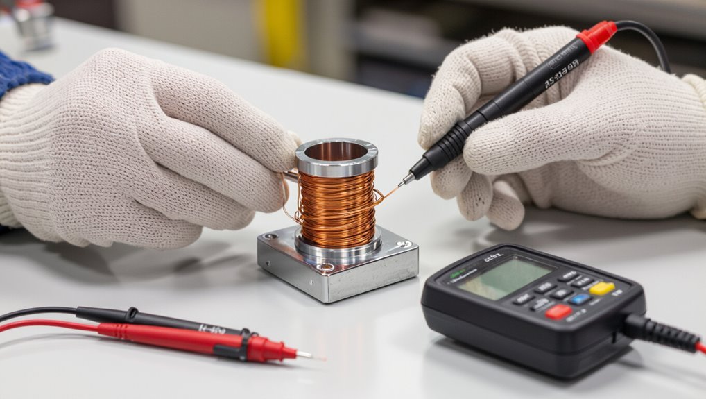
Common symptoms of a bad solenoid coil include no actuation, intermittent operation, humming or burning smells, and visible signs of overheating or insulation damage.
Quick resistance and continuity checks can confirm an open or shorted coil, while high current draw or physical damage often indicates replacement of the entire solenoid assembly is more practical.
Testing is recommended when symptoms are limited or electrical readings are ambiguous; replace the assembly when damage is obvious or repair is impractical.
Common symptoms of a bad solenoid coil
How can one quickly recognize a failing solenoid coil? Common symptoms include intermittent or no actuation, buzzing or humming, overheating, visible burn marks, and tripped fuses or relays.
Reduced pull force, slow response, or stuck plunger also indicate issues.
Technicians use how to test a solenoid coil procedures—visual inspection, resistance and continuity checks—to confirm these symptoms before further action.
When to test the coil versus replacing the solenoid assembly
Having identified signs like intermittent actuation, buzzing, or visible damage, a technician must decide whether to test the coil or replace the entire solenoid assembly.
Test the coil when wiring looks intact, connectors are clean, and the unit is serviceable; replace the assembly if insulation is burnt, the plunger is seized, corrosion is severe, or labor/time costs exceed testing and repair.
Safety Precautions Before Testing a Solenoid Coil
Before testing a solenoid coil, the technician should don appropriate PPE such as insulated gloves and eye protection.
Electrical isolation and lockout/tagout procedures must be completed to remove power and prevent accidental energization.
Any connected pressurized or mechanically linked systems should be depressurized or mechanically secured before work begins.
Required personal protective equipment (PPE)
When preparing to test a solenoid coil, technicians must wear appropriate personal protective equipment to prevent electrical shock, burns, and exposure to sharp edges or hot surfaces.
Required PPE includes insulated gloves, safety glasses or face shield, flame-resistant clothing, and closed-toe, non-conductive footwear.
Hearing protection is recommended in noisy environments.
Disposable gloves may protect against contaminants but not electrical hazards.
Electrical isolation and lockout/tagout steps
Any electrical source that could energize the solenoid must be identified and isolated prior to testing.
Power feeds are de-energized, breakers or disconnects locked out and tagged per site procedures.
Verify zero energy with a properly rated tester.
Retain tagout documentation and notify affected personnel.
Only authorized trained personnel perform re-energization after completion and clearance.
Handling pressurized or mechanically linked systems
Inspect equipment linked to the solenoid for stored energy or mechanical restraints and secure those sources prior to electrical work.
Verify depressurization of pneumatic or hydraulic lines, drain reservoirs, and lock moving parts.
Tag energy-isolated valves and bleed points.
Use blocking or mechanical locks to prevent unintended motion.
Confirm zero-energy state with gauges or indicators before coil access or testing.
Tools and Materials You Need
Testing a solenoid coil requires a reliable multimeter set to measure resistance and voltage, with capacitance or diode settings useful for some diagnostics.
Additional items include a test light, clamp meter, stable power source, insulated jumper leads, and insulated screwdrivers for safe connections.
For more advanced troubleshooting, an oscilloscope, LCR meter, or dedicated continuity tester can be used.
Multimeter: features and settings required
Because accurate coil diagnostics depend on precise measurements, a reliable digital multimeter is essential for solenoid testing.
It should measure resistance (ohms) with good resolution, continuity with audible tone, and DC voltage/current ranges. Auto-ranging simplifies use; hold and backlight functions help in awkward positions.
Low input impedance and proper input protection improve safety and reduce false readings.
Additional tools: test light, clamp meter, power source, jumper leads, insulated screwdrivers
Beyond a capable multimeter, a few more hand tools and test devices make solenoid work faster and safer.
A test light quickly verifies power presence; a clamp meter measures coil current without disconnecting circuits.
A regulated DC power source and jumper leads allow controlled bench energizing. Insulated screwdrivers protect against shorts during adjustments.
Each tool speeds diagnosis while reducing risk.
Optional diagnostic equipment: oscilloscope, LCR meter, continuity tester
Several specialized instruments can reveal coil behaviors that basic tools miss.
An oscilloscope visualizes transient waveforms, spikes, and contact bounce during activation. An LCR meter measures inductance, capacitance, and resistance precisely, aiding coil health assessment.
A continuity tester quickly confirms circuit integrity and detects open windings. Together these diagnostics pinpoint faults, validate repairs, and complement multimeter and clamp meter checks.
Solenoid Coil Basics You Should Know
A solenoid coil is a wound conductor that produces a magnetic field when energized, converting electrical input into linear or rotary motion to actuate mechanisms.
Key specifications to note include rated voltage, coil resistance, and duty cycle, which determine compatibility and thermal limits.
Coils come in common varieties—DC versus AC, push versus pull, and specialized valve solenoids—each affecting test methods and expected readings.
What a solenoid coil is and how it works
A solenoid coil is a cylindrical winding of conductive wire designed to produce a controlled magnetic field when an electric current passes through it.
The magnetic field concentrates along the coil axis, generating force that moves a ferrous plunger or interacts with nearby magnetic components.
Operation relies on electromagnetic induction and field geometry to convert electrical energy into linear mechanical motion for valves, relays, and actuators.
Typical coil specifications: voltage, resistance, duty cycle
Voltage, resistance, and duty cycle form the core specifications that determine a solenoid coil’s electrical compatibility, heat generation, and usable operating pattern.
Voltage rating matches supply to prevent insulation breakdown.
Resistance dictates current draw and power dissipation (I = V/R, P = V^2/R).
Duty cycle specifies allowable energized time versus rest to manage temperature and longevity; adherence prevents overheating and premature failure.
Common types: DC vs AC, push/pull, valve solenoids
Different coil categories reflect their electrical source, motion style, and application: DC and AC coils differ in drive waveform and construction.
Push and pull types describe plunger movement, and valve solenoids are optimized for fluid control.
DC coils offer steady force and simpler electronics; AC coils handle alternating supply with laminated cores.
Push/pull choice depends on required stroke and mounting; valve coils focus on quick response and sealing.
Visual and Mechanical Inspection Steps
A quick visual and mechanical inspection can reveal obvious faults such as burns, discoloration, corrosion, or loose connections on the coil housing and terminals.
The examiner should check connectors, pins, and insulation for damage or contamination that could affect continuity and contact.
If testing requires removal, the technician must follow safety procedures to disconnect power, note wiring positions, and extract the coil without stressing adjacent components.
External inspection: burns, discoloration, corrosion, loose connections
When inspecting a solenoid coil externally, begin with a close visual scan for burns, discoloration, corrosion, and loose connections, since these indicators often reveal overheating, moisture ingress, or mechanical stress.
Note charred enamel, faded varnish, rusted metal, and greenish deposits.
Check mounting points and exposed wiring for movement or fraying.
Document findings and isolate the device for further testing or repair.
Checking connectors, pins, and insulation
Inspect connectors, pins, and insulation closely for signs of wear, deformation, corrosion, or insulation breaches that can compromise electrical continuity and safety.
Verify pin straightness, secure seating, and absence of looseness or oxidation.
Check insulating sleeves and wires for cracks, brittleness, or melted areas.
Confirm connectors mate firmly without play and that any locking clips or seals are intact and functional.
How to safely remove the coil for testing
Having confirmed connector integrity and insulation condition, proceed to remove the coil for hands-on visual and mechanical inspection by first isolating power and relieving any stored pressure or fluid in the system.
Wear insulated gloves, tag out power, and drain lines.
Note orientation, document mounting fasteners, disconnect electrical leads, and gently extract the coil.
Inspect for cracks, corrosion, deformations, and debris before testing.
Multimeter Tests: Step-by-Step
The technician begins multimeter testing by measuring coil resistance with an ohmmeter, comparing the reading to the manufacturer’s expected ohms to spot shorted or open windings.
A continuity check follows to confirm whether the circuit registers closed or open, with an open reading indicating a break in the coil.
If leakage or insulation breakdown is suspected, a megohmmeter is used to measure insulation resistance and identify unacceptable leakage to ground.
Measuring coil resistance (ohmmeter) procedure and expected values
A basic multimeter set to the low ohms range provides a quick way to verify a solenoid coil’s continuity and approximate condition: Disconnect power, isolate coil leads, and measure resistance across terminals.
Record stable resistance; compare to manufacturer specs (typically low ohms for power solenoids, higher for pilot coils).
Significant deviation indicates shorted turns or open winding; document values for troubleshooting.
Continuity test interpreting open/closed readings
When a multimeter is set to continuity mode and connected across solenoid coil terminals, it reports either a closed circuit (usually with a beep and low ohm reading) indicating intact winding, or an open circuit (no beep, infinite resistance) indicating a break in the coil.
A stable closed reading confirms continuity; intermittent beeps or fluctuating resistance suggest partial breaks, poor connections, or corroded terminals requiring repair or replacement.
Insulation resistance and leakage checks with megohmmeter (when needed)
Several situations call for insulation resistance testing with a megohmmeter: suspected moisture ingress, aging insulation, high-voltage systems, or when a standard continuity check appears normal but intermittent leakage is suspected.
The technician isolates the coil, applies the prescribed test voltage, records megohm readings, and compares against manufacturer limits.
Low values indicate leakage or breakdown; dry, clean coils should show very high megohm readings.
Live Tests and Functional Checks
With power safely applied at the correct voltage, the solenoid should be observed for proper actuation using insulated leads or a bench power supply with current limiting.
A test light or clamp meter can confirm the expected current draw during operation to identify electrical anomalies.
The technician should listen for the magnetic pull and watch for smooth mechanical movement or binding as part of the functional check.
Applying correct voltage to observe actuation safe methods
Before applying power, the technician verifies the coil’s rated voltage and any polarity or duty-cycle requirements to guarantee the test replicates normal operating conditions.
The technician uses a regulated bench supply or appropriate battery, sets voltage precisely, and limits test duration.
Insulating probes, a fuse or current limiter, and remote switching minimize shock and damage while observing audible click and mechanical movement for proper actuation.
Using a test light or clamp meter to verify current draw
Technicians confirm coil current by placing a test light or clamp meter in the circuit while energizing the coil. The chosen tool provides different information— a test light indicates whether current flows and roughly how strong the draw by brightness, whereas a clamp meter measures actual amperage without breaking the circuit.
Record readings, compare to specifications, and note intermittent or excessive draws indicating shorted turns, high resistance, or supply issues.
Listening and observing for magnetic pull and mechanical movement
Listen for the distinct snap or hum and watch for visible movement when the coil is energized, since these immediate auditory and visual cues confirm magnetic pull and basic mechanical function.
The technician notes armature travel, latch engagement, and consistent response under repeated activation.
Absence of sound or motion suggests weak winding, sticky plunger, or mechanical obstruction; further diagnostics with meters and disassembly follow.
Advanced Diagnostic Methods
Advanced diagnostics employ specialized instruments to reveal issues not visible in basic checks.
An oscilloscope verifies the coil drive waveform for distortion or timing faults, while an LCR meter quantifies inductance and impedance to detect winding degradation.
Thermal imaging identifies hot spots that indicate shorted turns or excessive resistance.
Using an oscilloscope to check coil drive waveform
Connect an oscilloscope to the coil drive circuit to visualize the voltage and current waveforms during operation, enabling precise assessment of timing, amplitude, and transient behavior that a simple multimeter cannot reveal.
Observe rise/fall times, duty cycle, and any ringing or overshoot.
Compare waveforms against expected profiles to identify drive faults, intermittent connections, diode clamp issues, or PWM anomalies affecting coil performance.
LCR meter for inductance and impedance testing
An LCR meter provides precise measurements of a solenoid coil’s inductance, resistance and impedance across frequency, enabling diagnosis of winding integrity, shorted turns, and resonance behavior that simple continuity checks miss.
The technician compares measured values to specifications, observes frequency-dependent impedance to detect faults, and uses phase angle and Q factor to assess coil quality.
Test setups require proper lead compensation and secure connections.
Thermal imaging to find hot spots
Thermal imaging quickly reveals localized heating in solenoid coils and associated components, making it a powerful diagnostic tool for detecting high-resistance joints, shorted turns, and insulation breakdown under load.
Technicians scan coils during steady-state operation, comparing temperature patterns to expected baselines. Hot spots indicate electrical or mechanical faults requiring repair or replacement.
Use calibrated cameras, observe safety distances, and document findings for trend analysis and verification.
Interpreting Test Results and Common Fault Patterns
Test results are next assessed to distinguish high resistance or open coils, which often indicate broken windings, corrosion, or poor connections and typically require cleaning, rewiring, or coil replacement.
Low resistance or shorted turns point to insulation failure and localized heating risks that usually necessitate coil replacement and inspection for thermal damage.
Intermittent readings often correlate with vibration, loose terminals, or marginal insulation and call for mechanical stabilization, retorquing, and repeated testing under operating conditions.
High resistance or open coil causes and remedies
Diagnose high resistance or an open solenoid coil by correlating multimeter readings with likely physical causes and simple remedies.
High resistance often indicates corrosion, loose connections, or partial wire breakage; clean terminals, tighten fittings, and reflow solder joints.
An open coil usually results from broken windings or severe overheating; inspect insulation, continuity, and replace the coil if repairs are impractical or unsafe.
Low resistance/shorted turns diagnosis and consequences
When a solenoid coil measures considerably lower resistance than its specified value, it often indicates shorted turns—localized insulation breakdown between adjacent windings that creates parallel current paths and reduces overall impedance.
This condition typically leads to excessive current draw, overheating, diminished magnetic force, and eventual coil failure, so readings must be interpreted in the context of the coil’s nominal resistance, its temperature, and any recent exposure to moisture, mechanical damage, or electrical surges.
Detection involves comparing measured resistance to specs, inspecting for burn marks, checking for hotspots during energization, and considering replacement since rewind or repair is rarely cost‑effective for small or sealed coils.
Intermittent faults and vibration-related issues
Consider intermittent faults—often caused by vibration, thermal cycling, or marginal solder/joint connections—as a distinct class of coil problems that require different interpretation of test data than steady-state failures.
Technicians should perform vibration, tap, and thermal stress tests while monitoring resistance, continuity, and insulation.
Record transient opens, fluctuating readings, and contact noise.
Repair by securing leads, reflowing joints, or replacing compromised coils.
When to Repair, Rewind, or Replace the Coil
Decisions about repairing, rewinding, or replacing a solenoid coil hinge on assessments of windings condition, insulation integrity, and the feasibility of restoring original specifications.
Cost comparisons should weigh repair or rewind labor and turnaround against the price and reliability of a new coil.
When replacing, the choice between OEM and aftermarket units requires consideration of compatibility, warranty, and long-term performance.
Criteria for repairability and rewind feasibility
Evaluating whether a solenoid coil should be repaired, rewound, or replaced depends on a concise evaluation of damage severity, cost-effectiveness, and expected remaining service life.
Assess insulation integrity, number and location of winding breaks, core damage, and contamination.
Consider availability of matching wire gauge and tooling, winding complexity, achievable insulation class, and whether repairs restore original specifications and reliability before committing to rewind.
Cost vs. replacement considerations
Weigh repair, rewind, and replacement by comparing total lifecycle costs, downtime impact, and the likelihood of restored performance meeting original specifications.
Consider labor, parts, testing, and warranty differences. Rewind may save on expensive units if insulation, core, and winding geometry allow reliable restoration.
Replace when costs approach or exceed new coil price, safety compliance is uncertain, or long-term reliability is critical.
OEM vs aftermarket replacement coils
After comparing repair, rewind, and replacement on cost, downtime, and reliability, the choice between OEM and aftermarket replacement coils becomes the next practical consideration.
OEM coils match original specifications, warranty support, and often longer life. Aftermarket options can be cheaper and more available but vary in quality.
Choose OEM for critical systems; consider reputable aftermarket suppliers when cost and lead time dominate decision factors.
Preventive Maintenance to Extend Coil Life
Preventive maintenance focuses on protecting the coil from environmental hazards through proper sealing and enclosure choices to prevent moisture, dust, and corrosive exposure.
Correct installation practices, including specified connector torque and secure mounting, reduce mechanical stress and electrical faults.
A routine inspection schedule with clear checklists and record keeping helps detect early degradation and documents maintenance actions.
Environmental protection and sealing strategies
Because solenoid coils are often exposed to moisture, dust, chemicals, and temperature extremes, implementing targeted environmental protection and sealing strategies is essential to extend service life and maintain reliable operation.
Use IP-rated enclosures, conformal coatings, potting compounds, and gasketing to prevent ingress.
Select materials resistant to chemicals and UV.
Provide ventilation or thermal barriers for temperature control and schedule inspections for seal integrity and corrosion.
Proper installation and connection torque
When installing a solenoid coil, correct mounting and precise terminal torque are critical to guarantee reliable operation and prevent premature failure.
Mounting surfaces should be clean, flat, and aligned to avoid stress.
Use manufacturer-specified torque values for terminals and mounting hardware; over- or under-tightening causes loose connections, heat, or deformation.
Recheck torque after initial run-in and vibration exposure.
Recommended inspection schedule and record keeping
Although routine visual checks catch obvious issues, a documented inspection schedule and consistent record keeping are essential to extend solenoid coil life and verify maintenance actions.
A recommended plan includes monthly visual inspections, quarterly electrical tests (resistance, insulation), and annual thorough assessments.
Records should log date, tester, readings, torque values, corrective actions, and parts replaced to identify trends, justify replacements, and support warranty claims.
Common Testing Mistakes and How to Avoid Them
Common testing errors can lead to false diagnoses or damaged equipment if not recognized and corrected. The following brief list highlights the most frequent pitfalls and what to watch for when verifying a solenoid coil.
Careful adherence to proper procedures prevents misinterpretation and unsafe practices.
- Misreading multimeter results
- Testing on a powered circuit without isolation
- Ignoring temperature and duty-cycle effects
Misreading multimeter results
How can a simple multimeter reading lead to an incorrect diagnosis of a solenoid coil? Misinterpretation arises from wrong range selection, poor probe contact, residual circuit continuity, or ignoring temperature effects.
Measuring resistance without noting coil inductance or intermittent opens can mislead.
Proper technique: select correct mode, guarantee solid connections, isolate coil, and repeat readings to confirm consistency before declaring failure.
Testing on a powered circuit without isolation
Never test a solenoid coil while it remains connected to a live circuit without first isolating power, because voltage presence can produce misleading readings, damage test equipment, or create personal injury hazards.
Tests on energized circuits risk parallel paths, phantom continuity, and false resistance or continuity results.
Always de-energize, lock out/tag out, and verify zero voltage before measuring to guarantee accurate, safe diagnostics.
Ignoring temperature and duty-cycle effects
After de-energizing and verifying a solenoid before testing, technicians must also account for temperature and duty-cycle effects that alter coil performance.
Temperature shifts resistance and magnetic properties; cold coils may read high resistance, hot coils low.
Duty cycle affects heating and recovery—measure under representative conditions or allow stabilized temperatures.
Document ambient conditions and apply correction factors to avoid misdiagnosis.
Quick Reference Tables and Readouts
Quick reference tables and readouts give technicians immediate guidance on expected values and likely faults. Below is a concise lookup for typical resistance ranges and symptom-to-fault correlations:
| Item | Reference |
|---|---|
| Coil resistance by voltage/type | 10–50 Ω (12V), 100–500 Ω (24V), varies by coil design |
| Symptom → Probable fault | No click → open coil; weak pull → high resistance/intermittent |
These tables should be used as starting points for measurements and troubleshooting.
Typical resistance ranges by coil voltage and type
A concise reference for typical solenoid coil resistances helps technicians quickly determine whether a coil is within expected tolerance for its voltage and type.
Typical ranges:
- 12V automotive coils 0.5–5 Ω (low‑ohm);
- 24V industrial coils 2–20 Ω;
- 48–120V control coils 50–500 Ω;
- high‑voltage pilot coils 1k–10k Ω.
Note variance by manufacturer, duty cycle, and temperature.
Common symptom-to-fault correlation table
One concise table links observable symptoms to the most likely coil faults and recommended immediate checks, enabling technicians to triage issues quickly.
It lists symptoms (no pull, intermittent operation, buzzing, overheating, high current), probable causes (open winding, shorted turns, loose connector, low supply, coil saturation), diagnostic steps (resistance, insulation, supply voltage, continuity, thermal inspection) and priority actions.
Step-by-Step Checklist for Field Technicians
The field technician follows a concise checklist to guarantee safe, efficient, and repeatable solenoid coil testing.
It covers tasks to complete before arrival, the on-site testing sequence, and steps for documenting results and recommendations.
This structured approach reduces errors and speeds troubleshooting.
- Preparation before arrival
- On-site testing sequence
- Post-test documentation and recommendations
Preparation before arrival
Prepare a concise kit and checklist before departing for the site to guarantee efficient, safe solenoid coil testing.
The technician verifies required tools, spare parts, and calibrated multimeter; confirms PPE, lockout/tagout materials, and portable lighting; reviews schematic and access permissions; checks vehicle stock, battery chargers, and communication devices; and notifies site personnel of arrival time and safety constraints.
On-site testing sequence
Having confirmed tools, documentation, and site permissions, the technician proceeds with a structured on-site testing sequence to verify solenoid coil condition and circuit integrity.
Steps: lockout/tagout, visual inspection, measure coil resistance, insulation/resistance test, check supply voltage and continuity, apply controlled actuation if safe, observe mechanical response, record anomalies, isolate faults, and prepare for safe restoration or escalation.
Post-test documentation and recommendations
A concise, orderly report guarantees test results are useful for maintenance decisions and compliance records.
The technician logs coil ID, location, test date/time, instrument settings, measured resistance/insulation values, and pass/fail status.
Note observed defects, corrective actions, and parts replaced. Attach photos and meter screenshots.
Recommend follow-up interval and safety warnings. Store records per site protocol for traceability and audits.
Visual Aids and Diagrams to Include
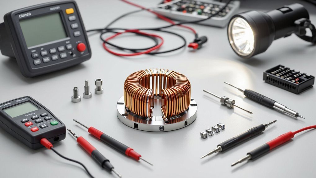
The section should present clear illustrations showing multimeter probe placement on coil terminals to guarantee correct continuity and resistance measurements.
Include wiring diagrams and connector pinout tables for common solenoid models to aid quick identification in the field.
A concise flowchart mapping diagnostic steps and decision points will help technicians reach correct conclusions efficiently.
Multimeter probe placement on coil terminals
Position probes directly on the solenoid’s coil terminals to obtain an accurate resistance reading, ensuring the meter leads contact clean, exposed metal and not insulated or corroded surfaces.
Place black (common) on one terminal and red (positive) on the other, maintain steady pressure, avoid sliding.
For compact terminals use fine-tipped probes or alligator clips.
Record readings and repeat to confirm consistency.
Typical wiring and connector pinouts
When identifying typical solenoid wiring and connector pinouts, technicians should expect a small set of standardized arrangements—commonly two-terminal coils, three-pin connectors with a switched power and ground plus a signal or diode, and multi-pin modules that include power, ground, control input, and feedback lines.
Diagrams should label pin numbers, wire colors, continuity paths, and diode orientation; include a legend and common vehicle or equipment examples.
Flowchart for diagnostic decision-making
Begin by mapping the diagnostic path as a clear decision tree that guides technicians through successive tests and outcomes, from initial visual inspection to final component replacement.
The flowchart should include nodes for visual checks, continuity/resistance, insulation, coil activation, signal/input verification, and failed/pass branches.
Use standardized symbols, brief labels, and color-coding for swift interpretation and consistent troubleshooting.
Conclusion
A concise final check confirms that systematic testing—visual inspection, continuity and resistance checks, insulation testing, and functional trials—reliably identifies solenoid coil faults. For instance, a field tech diagnosed a farm irrigation failure by measuring an open circuit in a solenoid coil, replacing it before a heatwave ruined seedlings; timely testing prevented crop loss and saved the farmer from costly repairs. Routine, safe procedures minimize downtime and extend component life.