How to Replace a Thermocouple on a Water Heater: Step-by-Step DIY Guide
To replace a thermocouple on a water heater, follow these steps for a safe and effective process. Start by turning off the gas supply and ensuring proper ventilation while wearing personal protective equipment (PPE). Next, remove the access panels to access the thermocouple. Disconnect the old thermocouple from both the pilot assembly and the gas control. Install the new thermocouple, ensuring the tip is centered in the pilot flame, and secure all connections without over‑tightening. Finally, relight the pilot, check for gas leaks, and test the millivolts to ensure everything is functioning correctly. Follow this guide for a detailed, step-by-step process.
What a Thermocouple Does in a Water Heater and Why Replacement May Be Needed
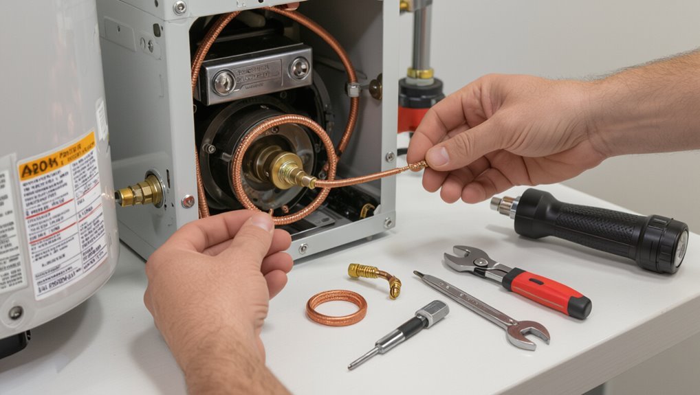
The thermocouple senses pilot flame temperature and signals the gas valve to stay open, making it essential for safe burner operation.
Typical signs of a failing thermocouple include a pilot that won’t stay lit, intermittent heating, or the pilot extinguishing unexpectedly.
Because a faulty thermocouple can allow gas to flow without a lit pilot or shut off heat unexpectedly, it poses both fire and carbon monoxide hazards.
Role of the thermocouple in gas water heaters
Because it senses the pilot flame and converts that heat into a millivolt electrical signal, a thermocouple acts as the safety switch that keeps gas flowing only when the burner is lit.
It prevents gas leaks by shutting the valve if flame is absent. Understanding this role helps users approach how to replace a thermocouple on a water heater safely and effectively.
Common signs the thermocouple is failing
When a thermocouple begins to fail, it typically exhibits a small set of clear, diagnosable symptoms that indicate it no longer reliably senses the pilot flame or produces sufficient millivoltage to hold the gas valve open.
Common signs include a pilot that won’t stay lit, intermittent heating, frequent relighting cycles, and visible corrosion or soot on the thermocouple tip indicating degraded performance.
Safety risks of a faulty thermocouple
A faulty thermocouple compromises the water heater’s safety system by failing to reliably detect the pilot flame and shut off gas flow, which can allow unburned gas to accumulate or cause burner instability.
Replacement is therefore necessary not only to restore proper operation but to prevent risks such as gas leaks, accidental ignition, and carbon monoxide production.
Additional hazards include system overheating, equipment damage, and potential explosion risk.
Tools, Materials, and Safety Precautions Required
A concise checklist of tools and replacement parts—wrenches, a new thermocouple matched to the heater model, thread sealant, and a gas-rated leak detector—should be assembled before starting the job.
The correct thermocouple is selected by matching model specifications, length, and connection type to the existing unit.
Gas safety precautions, a cleared and ventilated work area, and clear criteria for when to call a professional (e.g., uncertain gas fittings, persistent leaks, or lack of experience) must be established.
Tools and replacement parts checklist
Several essential tools and parts are required before starting the thermocouple replacement to guarantee the job proceeds safely and efficiently.
The technician should gather tools, parts, and PPE, confirming compatibility and condition. Typical checklist items include a basic wrench set, replacement thermocouple, and leak-tested fittings.
Verify gas shutoff tools and a lighter are available for relighting pilot.
- Adjustable wrench
- Replacement thermocouple
- Gas leak detector solution
How to choose the correct thermocouple for your heater model
With the checklist completed, the technician must select a thermocouple that matches the water heater’s make, model, and gas valve specifications to guarantee safe operation and reliable pilot control.
Reference the manufacturer’s part number, measure length and end fittings, verify temperature rating and millivolt output, and choose compatible materials (copper/iron types).
When uncertain, consult the heater manual or supplier for cross-reference guidance.
Gas safety precautions and preparing the work area
Safety is paramount when working on gas-fired water heaters, so the technician must shut off the gas supply, ventilate the area, and eliminate ignition sources before beginning.
Wear safety glasses and gloves, have a fire extinguisher nearby, and use a non-sparking flashlight.
Clear the workspace, protect flooring, keep tools organized, and verify no gas odor remains before proceeding with thermocouple replacement.
When to call a professional instead of DIY
When should a homeowner attempt a thermocouple replacement, and when is a licensed technician required?
A homeowner may proceed for simple, accessible pilots with basic tools, clear shutoff, and confidence in gas handling.
A licensed technician is required for complex systems, unclear diagnostics, persistent gas leaks, damaged fittings, unusual venting, or lack of local code familiarity.
Prioritize safety and permits.
Step-by-Step Preparation Before You Start
Before beginning work, the gas supply and pilot light should be turned off and the water supply shut off with system pressure relieved.
The technician should locate the thermocouple, remove any access panels, and expose the burner assembly.
Clear photos and notes must be taken to document wire and tube connections for accurate reassembly.
Turning off the gas supply and pilot light
Shut off the water heater’s gas supply and extinguish the pilot to eliminate ignition sources before handling the thermocouple.
Confirm the gas control valve is fully closed and, if present, turn off the appliance shutoff.
Wait a few minutes for residual gas to dissipate.
Do not attempt thermocouple work while the pilot is lit or the gas remains on; verify with smell or detector.
Shutting off the water supply and relieving system pressure
Begin by turning off the cold-water supply valve feeding the water heater to stop incoming water flow.
Then open a nearby hot-water tap to relieve pressure in the tank and downstream lines.
Drain a few gallons from the drain valve into a bucket to lower tank level if needed.
Verify pressure has equalized before proceeding with any access or component work.
Locating the thermocouple and removing access panels
With the water supply off and pressure relieved, the technician locates the thermocouple by inspecting the burner assembly at the base of the heater. The thermocouple is the thin metal probe positioned near the pilot light and connected by a copper or braided tube to the gas valve.
They remove ignition and access panels using a screwdriver, set fasteners aside, and clear insulation to expose the pilot assembly for replacement.
Taking photos/notes to document connections
Why document the connections before disconnecting anything? Photograph and label each wire, tubing, and fitting from multiple angles.
Note orientation, color codes, and terminal positions on paper or a phone memo. Clear images and brief notes prevent reconnection errors, save time, and guarantee safety.
Store photos where they are easily accessible during reassembly to confirm correct placement.
Removing the Old Thermocouple
The technician begins by loosening the fitting that secures the thermocouple to the gas control valve, taking care not to strip the connection.
Next, the thermocouple is detached from the pilot assembly and withdrawn from its clip or bracket.
Finally, surrounding components—pilot tube, fittings, and seals—are inspected for corrosion or damage that could affect the new thermocouple.
Disconnecting the thermocouple from the gas control valve
Begin by shutting off the gas supply and confirming the pilot is extinguished.
Then allow the area to cool before touching any components.
Using an adjustable wrench, loosen the nut securing the thermocouple at the gas control valve.
Pull the thermocouple straight out once free, avoiding bending.
Inspect the valve connection for debris or damage and set the old thermocouple aside for disposal.
Detaching the thermocouple from the pilot assembly
Carefully withdraw the thermocouple from the pilot assembly by loosening its mounting bracket or retaining clip and sliding the sensor tip clear of the pilot hood.
Guide the probe gently to avoid bending, unthread or lift any securing screw, and free the thermocouple lead from routing clips.
Remove it fully from the burner area, keeping track of hardware for correct reinstallation.
Inspecting surrounding components for damage
With the thermocouple removed and set aside, inspect the burner area and pilot assembly for signs of wear, heat damage, or soot buildup.
Examine wiring insulation, pilot tube integrity, electrode condition, and mounting brackets.
Look for corrosion, loose connections, or warped components that could impair ignition.
Note any debris or blockages and document parts needing cleaning or replacement before installing the new thermocouple.
Installing the New Thermocouple
The new thermocouple is routed and positioned so its tip sits squarely in the pilot flame for reliable sensing.
It is then secured at the pilot assembly and connected to the gas control valve, tightening the fitting to the manufacturer’s torque or snugness specification.
Finally, the installer checks routing to keep the lead clear of heat sources and pinch points before restoring gas and testing operation.
Positioning the thermocouple tip in the pilot flame
Position the new thermocouple so its tip sits directly in the center of the pilot flame, where the flame is hottest and most stable.
Verify the tip is aligned with the flame’s inner blue cone, not merely the outer yellow flicker.
Small adjustments may be needed while observing flame shape; guarantee consistent contact without bending the sheath.
Test pilot flame response after positioning.
Securing the thermocouple at the pilot assembly
After confirming the thermocouple tip sits securely in the pilot flame, attention shifts to fastening the body at the pilot assembly.
The installer aligns the thermocouple shaft with its mounting bracket or clip, slides it into the retaining slot, and secures any screws or spring clips.
Verify the thermocouple is straight, free of kinks, and firmly held without over-tightening that could deform the sensor.
Connecting the thermocouple to the gas control valve and tightening correctly
Carefully thread the thermocouple’s compression nut onto the gas control valve by hand until it seats.
Then use an appropriately sized wrench to tighten it just enough to form a gas-tight connection without distorting the sensor.
Make certain the thermocouple tip remains positioned at the pilot flame.
Avoid overtightening that can crush the tubing, and confirm the nut is snug with no visible gaps.
Verifying correct routing to avoid heat or pinch points
With the thermocouple secured to the gas control valve, attention shifts to routing the sensor tube so it avoids heat sources and pinch points.
The installer inspects the path, keeping the tube clear of burner flames, exhaust ducts, sharp edges and tight clamps.
Gentle curves prevent kinks; enough slack accommodates thermal expansion.
Secure clips spaced evenly, without compressing the tube, guarantee reliable operation.
Testing and Recommissioning the Water Heater
With the new thermocouple in place, gas supply is restored and the pilot is relit following the appliance’s safety procedure.
The technician observes pilot stability and flame shape, then verifies burner ignition and warm-water production.
Finally, a leak check and thorough safety inspection confirm the system is operating correctly before returning the heater to normal service.
Restoring gas and relighting the pilot safely
Restore gas flow and relight the pilot only after confirming the thermocouple and gas connections are secure, the burner assembly is clean, and all venting is unobstructed.
Follow manufacturer pilot lighting steps: set control to pilot, depress gas knob, ignite per instructions, hold for required warm-up, then release and turn to ON.
Check for gas odor; if detected, shut off and ventilate before calling a professional.
Observing pilot stability and flame characteristics
After the pilot is relit and the area is verified safe, attention should shift to the pilot flame and burner behavior to confirm proper operation.
Observe flame size, color, and steadiness: a steady blue flame with minimal yellow indicates correct combustion.
Watch for flickering, lifting, or interruption when other appliances operate.
If instability persists, shut gas off and inspect assembly, connections, or call a professional.
Testing burner operation and hot water production
Begin testing burner operation and hot water production by initiating a controlled run cycle: light the pilot, open the main gas valve, and set the thermostat to a mid-range temperature.
Observe burner ignition, flame stability, and consistent cycling.
Verify hot water at a nearby tap after several minutes, checking for steady temperature rise and adequate flow.
Record any irregularities for further adjustment.
Leak check and final safety inspection
Perform a thorough leak check and final safety inspection before returning the water heater to regular service.
Inspect all fittings, valves, and the replacement thermocouple joint for moisture.
Verify the T&P valve operation and confirm proper venting.
Restore covers and guarantee flame safety device remains secure.
Document findings and corrective actions.
- Check for visible drips and dampness
- Test T&P valve and drain
- Confirm proper combustion venting
Troubleshooting If the Heater Still Won’t Stay Lit
If the water heater still will not stay lit, the technician should first confirm the thermocouple is correctly positioned in the pilot flame and securely connected.
Next steps include inspecting the pilot assembly and gas control valve for faults, and using a multimeter to check millivolt output and interpret whether readings indicate a weak thermocouple or a downstream control failure.
If tests point to multiple failing parts, replacement of both the thermocouple and any faulty pilot or gas control components may be necessary.
Confirming correct thermocouple placement and connection
Once the thermocouple has been replaced, verifying its placement and electrical connection is essential to rule out installation errors as the cause of a persistent pilot failure.
Confirm the sensor tip sits securely in the pilot flame, straight and centered, with no insulation or debris blocking heat.
Make sure the compression nut is tight and the wire to the gas valve is clean, undamaged, and firmly connected.
Diagnosing pilot assembly or gas control valve problems
Begin troubleshooting the pilot assembly and gas control valve by systematically isolating each component to identify the source of a persistent pilot outage.
Inspect the pilot orifice for clogging, verify pilot flame shape and size, check pilot tubing for leaks or blockage, and guarantee the thermopile or sensor contacts are clean and secure.
Replace damaged pilot parts or the gas control valve as needed.
Multimeter tests and what voltage readings mean
Use a multimeter to measure the thermopile or thermocouple output and the gas control valve input to pinpoint where voltage is dropping.
Measure millivolts with pilot lit: typical thermocouple ~20–30 mV, thermopile higher (several hundred mV).
If source is proper but valve sees low voltage, wiring or connector fault likely.
Readings near zero indicate failed sensor or open circuit.
When multiple components may need replacement
Diagnose methodically when a water heater continues to fail despite a good thermocouple or thermopile, because multiple parts often contribute to pilot instability.
Inspect and test the pilot assembly, gas valve, control module, and wiring for faults or corrosion.
Replace any worn pilot orifice, faulty gas control, or intermittent ignition module.
Verify gas pressure and proper grounding before reassembly and final testing.
Maintenance Tips to Extend Thermocouple Life
A brief maintenance routine can considerably extend a thermocouple’s service life by catching wear and contamination early.
Technicians should follow a regular inspection schedule, clean the pilot assembly and thermocouple safely with appropriate tools, and address issues like soot, drafts, or corrosion that commonly cause premature failure.
Clear, periodic checks and simple preventive actions often prevent replacement and improve heater reliability.
Routine inspection schedule
Regularity is essential: establish a simple, consistent inspection schedule to catch wear and contamination before they cause pilot failure.
Inspect visually every three months for loose connections, corrosion, or physical damage.
Perform a functional check—confirm steady pilot flame and secure fittings—every six months.
Record findings and any minor adjustments.
Replace the thermocouple promptly if deterioration or intermittent operation is observed.
Cleaning the pilot and thermocouple safely
After establishing a routine inspection schedule, attention should turn to safe cleaning of the pilot assembly and thermocouple to prevent buildup that can impair sensing and cause pilot outages.
Power and gas must be shut off; wait for cooling. Use a soft brush or compressed air to remove soot and debris. Avoid abrasive tools or solvents.
Reassemble, test pilot ignition, and monitor for steady flame.
Preventing common causes of premature failure
When kept clean, properly aligned, and protected from corrosive conditions, a thermocouple will far outlast one that is repeatedly exposed to soot, moisture, or mechanical stress.
Regular inspections, gentle cleaning, correct positioning relative to the pilot flame, and prompt replacement of degraded fittings prevent failures.
Avoid vibratory contact, water leaks, and corrosive fumes; use recommended parts and follow manufacturer torque and clearance specifications.
Cost, Time Estimate, and Replacement Scenarios
Typical parts for a thermocouple replacement cost a few dollars to around $30, while hiring a professional adds labor fees that vary by region.
The replacement commonly takes 20–60 minutes for a competent DIYer, versus an hour or more including travel and diagnostics for a technician.
Full component replacement or replacing the gas valve may be more economical when multiple parts fail or when labor costs approach the price of a new assembly.
Typical costs for parts and DIY vs professional labor
A basic thermocouple for a gas water heater usually costs $10–$30, while a higher-quality or OEM unit can run $30–$60; additional parts (pilot assembly, mounting hardware, or a replacement gas valve) may add $10–$150 depending on need. DIY saves labor but risks errors; professionals charge $75–$200+ labor. Consider warranty, complexity, and safety.
| Item | Typical Parts Cost | Notes |
|---|---|---|
| Thermocouple | $10–$60 | Basic to OEM |
| Pilot assembly | $10–$80 | If damaged |
| Gas valve | $50–$150 | Major repair |
| Labor | $75–$200+ | Professional service |
Estimated time to complete the replacement
Most thermocouple replacements on standard residential gas water heaters take between 20 and 60 minutes from start to finish for a competent DIYer with basic tools.
This includes shutdown, cooling time, removal of the old unit, installation of the new thermocouple, leak checks, and relighting the pilot.
Variations depend on access, corrosion, connector type, and whether additional cleaning or minor valve adjustments are needed.
Situations where full component replacement is more economical
Recognize that replacing an entire pilot assembly or gas control valve can be more cost-effective than swapping a single thermocouple when age, corrosion, or multiple component failures are present.
Upfront parts costs are higher but reduce the likelihood of repeat service calls and extend overall system reliability.
Evaluate parts cost versus labor, expected remaining service life, diagnostic certainty, and potential downtime to decide between repair and full replacement.
Visual Aids and Reference Diagrams
The article presents clear diagrams showing typical thermocouple locations for tank, tankless, and gas furnace-style water heaters.
Illustrations also compare common pilot flame shapes and indicate the correct flame positioning relative to the thermocouple tip.
These visual aids help readers quickly identify proper installation points and flame alignment before beginning work.
Typical thermocouple locations by heater type
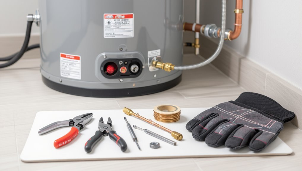
Different heater designs position the thermocouple where it can sense the pilot flame or combustion chamber reliably, so diagrams showing side-by-side tank, tankless, and gas-fired unit layouts clarify these locations.
Typical placements: adjacent to pilot tube at tank heaters; near burner assembly in gas-fired boilers; inside the combustion chamber or at the heat exchanger entry on tankless units for accurate flame sensing.
Common pilot flame shapes and correct positioning

Having established where thermocouples sit in various heater types, attention now shifts to the pilot flame itself—its shape and placement determine reliable heat exposure to the sensor.
A stable blue cone with a defined inner cone that envelopes the thermocouple tip by about 1/4–1/2 inch is ideal.
Yellow, lifting, or weak flames indicate adjustment, so repositioning or cleaning is required.
Conclusion
In conclusion, replacing a water heater thermocouple is portrayed as a tiny heroic quest: a modest twist of wrench and steady hand banishes the temperamental pilot flame, restoring domestic harmony. Armed with basic tools and clear steps, the homeowner transforms into a triumphant repair virtuoso, saving money and averting plumbing apocalypse. With routine checks and simple care, this small component will loyally guard the burner’s glow, keeping hot-water drama firmly at bay.