How to Install a Pipe Locator: Step-by-Step Guide for Accurate Underground Utility Detection
To install a pipe locator effectively, start by inspecting and powering both the transmitter and receiver. Select the appropriate frequency mode for the utility you’re targeting. Next, couple the signal using a direct connect, clamp, or sonde method. As you operate, sweep the receiver along your planned routes, aligning the antenna to find the peak signal. Mark the centerlines and record the depths and GPS points. To ensure accuracy, verify your findings with Ground Penetrating Radar (GPR) or hand probes, document any anomalies, and adhere to one-call and safety protocols. For further guidance, refer to detailed troubleshooting and verification methods.
Overview of Underground Pipe Locators and When to Use Them
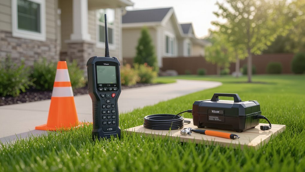
A pipe locator detects and maps underground utilities using methods such as electromagnetic tracing, radio frequency detection, or ground-penetrating radar, each suited to different materials and depths.
Professionals and homeowners commonly use locators before construction, DIY projects, or repair work to prevent damage and service interruptions.
Legal and safety steps—calling 811, securing permits, and arranging safe site access—should precede any locating activity.
What a pipe locator does and types of locators (electromagnetic, radio, ground-penetrating radar)
Pipe locators identify the position and often the depth of buried pipes and utilities by detecting signals or contrasts in subsurface materials. They convert detected signals into visual or audio cues to map lines.
Types include electromagnetic locators for conductive pipes, radio frequency transmitters for passive tracing, and ground-penetrating radar for nonmetallic utilities.
Guidance on how to install pipe locator focuses on calibration, grounding, and safe operation.
Common scenarios for locating underground utilities (construction, DIY, repairs)
Many projects—from large-scale construction to weekend DIY repairs—require precise knowledge of underground utility locations to prevent damage, delays, and safety hazards.
Contractors use locators for site grading, trenching, and installing foundations; plumbers and HVAC technicians locate service lines before repairs; landscapers and homeowners check for irrigation, cable, and gas lines prior to digging.
Emergency responders also rely on quick detection during failures.
Legal and safety obligations before locating (call 811, permits, site access)
Before any locating work begins, legal and safety obligations must be confirmed: contacting regional one-call services (call 811 in the U.S.), securing required permits, and arranging clear site access and boundaries.
The operator must verify utility notifications, obtain landowner permission, review local regulations, and coordinate traffic or excavation controls.
Documentation of clearances and emergency procedures guarantees compliance and reduces risk during locating operations.
Essential Equipment and Personal Protective Gear
The installer assembles primary tools such as a transmitter, receiver, signal clamp and sondes before beginning work.
Optional aids like a GPR unit, soil probes, updated maps and GPS improve location accuracy in complex conditions.
Recommended PPE and on-site safety supplies—hard hat, high-visibility vest, gloves, eye protection and first-aid kit—are kept readily available.
Primary tools: transmitter, receiver, signal clamp, sondes
Select and prepare the key instruments—transmitter, receiver, signal clamp, and sondes—before conducting any locating task, as each performs a distinct role in applying and detecting signals on buried utilities.
The transmitter injects a signal; the receiver traces it. Signal clamps couple without direct connection for live lines. Sondes are inserted into non-conductive conduits.
Verify calibration, battery levels, and secure connections prior to use.
Optional equipment: GPR unit, soil probes, maps, GPS
Include optional tools such as a ground-penetrating radar unit, soil probes, updated utility maps, and a GPS receiver to enhance locating accuracy and situational awareness.
GPR detects non-metallic utilities and depth variations; soil probes verify shallow targets. Updated maps provide historical context and known lines.
GPS records precise hits for documentation and future reference, improving planning and reducing survey time.
Recommended PPE and on-site safety supplies
After gathering optional detection tools like GPR, soil probes, updated maps, and a GPS receiver, personnel should outfit themselves with proper personal protective equipment and on-site safety supplies to manage hazards uncovered during locating.
Recommended items include high-visibility vests, hard hats, safety boots, gloves, eye protection, hearing protection, and respiratory masks.
Carry barricade tape, signage, first-aid kit, spill kit, and communication devices.
Preparing the Site for Accurate Detection
Before beginning detection, the operator consults utility maps and site plans to establish known lines and access points.
Surface features and entry locations are then clearly marked to guide the survey.
Finally, loose debris is removed and environmental factors such as nearby electrical interference or standing water are controlled to improve signal accuracy.
Reviewing utility maps and site plans
When preparing the site for pipe locating, technicians should systematically review available utility maps and site plans to identify known asset locations, depth notations, and conflicting infrastructure.
They cross-reference records with survey markers, note discrepancies or undocumented lines, and flag high-risk zones.
This review informs locating strategy, required permits, and equipment selection while documenting uncertainties for on-site verification and contractor coordination.
Marking visible surface features and access points
Following the review of maps and site plans, technicians walk the site to identify and mark visible surface features and access points that will guide locating efforts.
They tag valve covers, meter boxes, manholes, utility poles, transformer pads, exposed piping and service risers with durable markers or flags.
Markings are recorded on the site sketch and cross-referenced to planned scan grids for efficient, accurate detection.
Removing surface interference and controlling environmental factors
Clear the area of loose debris, vegetation, and temporary obstructions that can deflect signals, create false returns, or impede access to scan grids.
Inspect for nearby metallic fences, parked vehicles, and overhead power lines; relocate or mark them.
Account for moisture, soil composition, and nearby electromagnetic sources.
Establish controlled scan patterns, note environmental conditions, and record any factors that could affect locator accuracy for later calibration.
Step-by-Step Guide to Installing and Using a Pipe Locator
The operator begins by inspecting and setting up the locator, then calibrates it and selects the appropriate frequency or mode.
A signal is established on the target pipe via direct connect, clamp, or sonde insertion, after which the receiver is used to trace the route and confirm depth readings.
Finally, the located route is marked and recorded to guide safe excavation.
Step 1 Inspect and set up the locator equipment
Begin by visually inspecting the locator, transmitter, batteries, and leads for damage, corrosion, loose connectors, or missing parts.
Verify battery charge levels and install fresh or fully charged cells.
Confirm leads and clamps are correctly rated and securely attached.
Check display, controls, and speaker operation.
Organize accessories, protective cases, and grounding stakes.
Record serial numbers and condition before deployment.
Step 2 Calibrate and select the correct frequency/mode
Next, calibrate the locator and choose the appropriate frequency and mode based on the utility type, soil conditions, and proximity to other conductive assets.
Verify instrument zero, perform ground balance, and set sensitivity to avoid overload.
Select low frequencies for long-range detection, higher frequencies for shallow or non-metallic targets when using compatible modes.
Log settings before proceeding.
Step 3 Establish a signal on the target pipe (direct connect, clamp, or sonde insertion)
Establish a clear, continuous signal on the target pipe using the appropriate method—direct connect, clamp, or sonde—so the locator can reliably trace its route and depth.
The operator selects method based on accessibility and pipe material: direct-connect for exposed conductors, clamp for live lines without interruption, or battery-powered sonde inserted into voids or conduits.
Guarantee secure connections and verify transmitter output before proceeding.
Step 4 Trace the pipe route with the receiver and confirm depth readings
With the transmitter confirmed and connections secure, the operator sweeps the receiver along the anticipated route, aligning the antenna until the signal peaks to mark the centerline.
The operator then follows that line to map the pipe’s path. Readings are taken at regular intervals, depth estimates confirmed by holding the receiver steady over maxima, and anomalies investigated by rescanning laterally and adjusting gain to verify continuity.
Step 5 Marking and recording the located route for excavation
After confirming the pipe centerline and depth profile, the operator prepares to mark and record the route for excavation.
They place durable, visible markers at regular intervals, note offsets and depth changes, and sketch the route on site plans.
GPS coordinates and time-stamped photos are logged.
All markings include utility type, date, and operator ID for excavation crews and record-keeping.
Step 6 Verifying findings with secondary methods (GPR, hand probing)
Verify results using at least one secondary method to confirm the pipe locator’s findings before excavation begins.
The technician should employ ground-penetrating radar (GPR) to image subsurface anomalies and use careful hand probing at marked points to physically verify depth and material.
Document discrepancies, reconcile signals, and adjust markings.
If uncertainty remains, cease work and engage utility owners or specialized surveyors for further assessment.
How to Interpret Locator Readings and Depth Measurements
The operator must learn to read signal strength patterns, apply peak/shoulder techniques and use nulling to pinpoint a line and estimate depth.
Certain reading characteristics—stable narrow peaks, broad shoulders, or weak fluctuating signals—can suggest pipe type and material.
When depth results are ambiguous or vary, the technician should recheck orientation, test multiple frequencies, and corroborate with alternate methods.
Understanding signal strength, peak/shoulder methods, and nulling
A clear grasp of signal strength, peak and shoulder methods, and nulling is essential for correctly interpreting locator readings and estimating pipe depth.
Signal strength indicates proximity; operators sweep to find the peak response directly above a conductor.
The shoulder method uses adjacent high readings for alignment.
Nulling cancels out interfering signals to reveal weak conductors, improving accuracy in congested utility areas.
Common indicators of pipe type and material in readings
Building on signal-strength techniques and nulling practices, operators can interpret specific reading patterns to infer pipe type and material.
Consistent strong continuous signals often indicate metallic pipes; intermittent or weak signals suggest nonmetallic conduits or coated lines.
Harmonic content, phase shifts, and conductivity estimates help distinguish cast iron, steel, copper, or plastic with tracer wire.
Cross-checks with known maps increase confidence.
Dealing with ambiguous or fluctuating depth results
Often, ambiguous or fluctuating depth readings result from signal interference, complex ground conditions, or multiple nearby conductors, requiring systematic verification rather than immediate correction.
The operator should cross-check with alternate frequencies, reposition transmitter and receiver, perform multiple passes perpendicular to the line, and use peeking/sonde methods.
Document inconsistent readings, mark suspected zones, and consult utility records before excavation to mitigate risk.
Troubleshooting Common Problems During Location
When signals are unclear, the operator should first consider external interference from nearby utilities, power lines, or surface noise and adjust frequency or positioning accordingly.
Weak or absent signals often stem from poor connections, incorrect transmitter settings, or insulation on the target pipe and can usually be remedied by checking clamps, using sondes, or increasing output.
Misleading responses may arise from parallel utilities or conductive soils, so verification with multiple passes and alternate frequencies is recommended.
Interference from nearby utilities, power lines, or surface noise
Although a locator is designed to detect target signals, nearby utilities, energized power lines, and surface noise can create competing electromagnetic fields that obscure or distort readings.
Operators should recognize erratic traces, spurious peaks, or inconsistent depth estimates as interference indicators.
Mitigation includes repositioning, using differential or frequency-shift modes, employing broadband filters, isolating suspect conductors, and documenting conditions before proceeding to avoid misidentification.
Weak or no signal: causes and fixes
Diagnose weak or absent signals by systematically checking equipment, connections, and site conditions to isolate the cause.
Technicians should verify transmitter output, battery levels, lead integrity, and clamp placement. Confirm correct frequency and coupling method.
Inspect target pipe continuity and joints for breaks or corrosion. Move to alternative access points, increase transmitter power gradually, and re-scan to confirm restored signal strength.
Misleading signals from parallel utilities or conductive soils
If signals seem to jump or split unexpectedly, the technician should consider interference from parallel utilities or conductive soils as likely culprits.
Parallel metallic lines can induce coupled signals causing false routes; closely spaced cables require differential tracing and signal isolation.
High soil conductivity attenuates or spreads fields, so adjusting frequency, increasing signal strength, or using alternative locating techniques reduces misleading readings and improves verification.
Best Practices for Accurate and Safe Utility Detection
Routine calibration, battery care, and regular equipment maintenance guarantee locator accuracy and reduce downtime.
Clear documentation—photos, sketches, digital maps, and coordinates—creates an auditable record for future reference.
Coordination with utility owners and excavation teams minimizes risk and confirms findings before any ground disturbance.
Routine calibration, battery care, and equipment maintenance
Maintain consistent calibration, battery care, and equipment maintenance to guarantee pipe locators deliver reliable, accurate readings and to reduce safety risks on-site.
Establish scheduled calibration per manufacturer specs, log dates and results, and replace batteries before low-charge thresholds.
Inspect cables, connectors, antennas, and housings for wear, clean contacts, and store equipment dry.
Promptly repair or retire defective units to maintain field integrity.
Documenting findings: photos, sketches, digital maps, and coordinates
After ensuring locators are calibrated and serviceable, field teams should record detection results systematically to preserve accuracy and support safety decisions.
Documentation must be clear, timestamped, and verifiable. Recommended records include:
- Photographs with scale and north arrow, labeled to features and anomalies.
- Simple sketches noting depths, offsets, and landmarks.
- Georeferenced digital maps or coordinates exported in standard formats for integration and review.
Coordination with utility owners and excavation teams
Engage utility owners and excavation teams early to establish clear responsibilities, confirm known network layouts, and coordinate hand-off procedures before any ground disturbance.
The locator team documents detection results, shares maps and confidence levels, and schedules joint site reviews. Responsibilities for verification, marking, and safe digging are agreed.
Communication protocols, emergency contacts, and change-control procedures are recorded to minimize risk and delays.
Comparison of Locating Methods and When to Use Each
Different locating methods offer trade-offs in depth, accuracy, and suitability for varying pipe materials and site conditions. Electromagnetic locating and ground-penetrating radar (GPR) each perform better in specific scenarios, while direct connect/clamp techniques and sonde insertion provide alternative ways to trace lines depending on access and signal coupling. The table below summarizes key contrasts to guide method selection.
| Method Type | Strength | Typical Use Case |
|---|---|---|
| Electromagnetic | High accuracy on metallic/charged lines | Tracing energized or conductive pipes |
| Ground-penetrating Radar | Non-metallic detection, depth profiling | Locating plastic pipes and complex subsurface features |
| Direct connect/Clamp vs Sonde | Direct connect/clamp = strong signal on conductors; sonde = independent in open runs | Use clamps/direct connect when accessible; use sonde for inaccessible or non-conductive segments |
Electromagnetic locating vs. ground-penetrating radar
When choosing a method to locate buried utilities, professionals typically weigh electromagnetic (EM) locating against ground-penetrating radar (GPR) based on signal behavior, subsurface conditions, and the information required;
EM excels at tracing conductive lines like metal or traced nonmetal pipes, while GPR maps a wider range of materials and provides depth profiles in suitable soils.
EM is fast, reliable for energized or traced lines;
GPR detects nonconductive targets and complex stratigraphy but is limited by conductive soils, depth, and operator interpretation.
Direct connect/clamp vs. sonde insertion
Although both direct connect/clamp methods and sonde insertion serve the same goal of locating underground pipes, they rely on different signal strategies and are suited to distinct circumstances.
Direct connect/clamp transmits a stronger, traceable signal on metallic lines or exposed fittings.
Sonde insertion emits a localized radiated signal for nonmetallic or inaccessible conduits and precise vertical mapping, especially in complex networks.
Cost, Training, and Hiring Professionals
A brief overview of costs, training, and hiring considerations frames the practical choices of acquiring and operating a pipe locator.
Estimated equipment prices and ongoing operational expenses are weighed alongside required training, certification, and demonstrated operator competence.
Guidance is provided on circumstances that justify hiring a professional locator versus pursuing a DIY approach.
Estimated equipment and operational costs
Budgeting for pipe locator deployment requires balancing upfront equipment purchases, recurring operational expenses, and labor-related costs such as training or contracting specialists.
Estimated costs include purchase or rental of locators and accessories, calibration and maintenance, batteries and consumables, software licenses, and insurance.
Labor charges vary by in-house staffing versus subcontracting. Contingency for repairs, upgrades, and site mobilization should be included in forecasts.
Required training, certification, and operator competence
Effective pipe locator deployment depends as much on operator competence as on equipment quality; trained, certified technicians reduce risk, improve accuracy, and guarantee regulatory compliance.
Employers should require formal training, manufacturer courses, and industry certifications (e.g., NULCA, ASNT-equivalent).
Regular recency training, documented proficiency testing, and familiarity with safety protocols, signal interpretation, and site documentation are essential for consistent, defensible utility detection results.
When to hire a professional locator vs. DIY
When should a property owner attempt utility locating themselves versus hiring a professional?
A homeowner may DIY for small, non-critical projects if trained, equipped, and comfortable accepting risk.
For complex sites, high-consequence utilities, unclear records, or legal liability concerns, hiring a certified locator is prudent.
Professionals offer advanced equipment, experience, and insurance, often justifying higher costs through risk reduction and regulatory compliance.
Safety Checklist Before Excavation
Before breaking ground, the team completes final verification steps and confirms on-site communication protocols to guarantee everyone understands locate marks and excavation limits.
A clear emergency plan is posted and reviewed, including shutdown procedures and contact numbers for utility owners and emergency services.
Procedures for promptly reporting and containing damaged utilities are established to minimize risk and coordinate repairs.
Final verification steps and on-site communication
Confirm all markings, documentation, and detector readouts match the planned excavation layout before work begins.
The team verifies color codes, depth notes, and GPS coordinates, reconciles any discrepancies, and signs off on the site log.
A designated communicator coordinates hand signals and radio protocols, guarantees everyone understands exclusion zones, and verifies standby safety equipment is accessible prior to initiating any ground disturbance.
Emergency procedures and reporting damaged utilities
Establish clear emergency procedures and reporting steps so the crew can respond immediately to utility strikes or unsafe conditions.
The plan should list shutdown actions, evacuation routes, first‑aid roles, and emergency contacts. Document required notifications to utility owners, regulators, and supervisors, preserve the scene for investigation, and secure the area.
Conduct drills and guarantee all personnel understand incident reporting timelines and evidence preservation.
Tips to Extend Locator Lifespan and Improve Accuracy
Proper upkeep and disciplined field habits prolong a pipe locator’s service life and sharpen its readings.
Recommended practices include:
- Store in a dry, padded case and clean contacts and sensors after use.
- Adopt consistent setup routines and double-check connections to reduce errors and rework.
- Replace batteries and inspect cables regularly to avoid signal loss or damage.
Storage and cleaning recommendations
Several simple habits greatly extend a pipe locator’s service life and maintain its accuracy: store the unit in a dry, temperature-stable case, remove batteries during long-term storage, and clean contact points and sensor surfaces after use to prevent corrosion and debris buildup.
Wipe housing with a soft cloth, use approved cleaners for electronics, protect connectors with caps, periodically inspect seals, and document maintenance dates.
Field habits that reduce errors and rework
Beyond routine storage and cleaning, operators can adopt a set of field habits that minimize errors and reduce rework.
Regularly perform pre-shift checks, calibrate before use, and confirm ground balance. Record site conditions and signal settings.
Use consistent sweep patterns, avoid excessive pressure on probes, and document anomalies.
Maintain batteries and connectors, and train crews on standardized procedures to guarantee repeatable, accurate locating.
Conclusion
When undertaking underground pipe locating, one must prioritize preparation, employ proper equipment, and follow methodical procedures. One must verify calibrations, secure personal protective gear, and confirm readings before digging. One must weigh in-house capability against professional services, balance cost against risk, and choose the appropriate locating method. One must maintain and calibrate tools, document findings, and follow safety protocols. Above all, one must protect people, preserve infrastructure, and prevent costly mistakes.