How to Identify Thermocouple Type: A Simple Step-by-Step Guide
To identify a thermocouple, start by examining its visual features and conducting basic measurements. Key steps include inspecting the sheath material, insulation color, and connector shape, as well as looking for any stamped identification codes. Determine the type of junction—whether it’s exposed, grounded, or ungrounded—and use a multimeter to check continuity. Measure the open-circuit voltage at a known cold reference point, and compare your readings to standard reference tables or use ice-point and boiling tests for verification. Additionally, color bands and markings can provide further confirmation of the thermocouple type. Follow-up diagnostic steps and tables can offer more detailed verification if needed.
How to Identify Thermocouple Type Quickly and Reliably
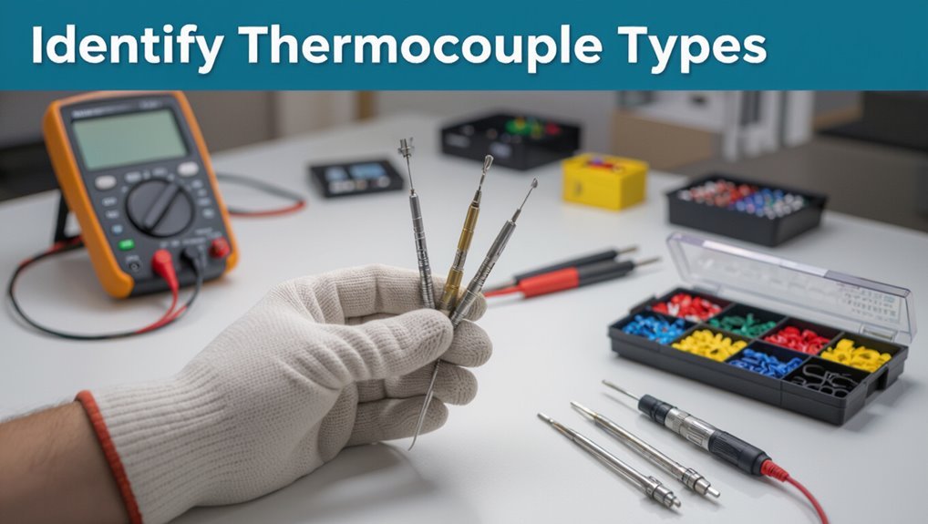
A thermocouple is a temperature sensor formed by two dissimilar metal wires joined at one end; identifying its type is essential because different types have distinct temperature ranges, sensitivities, and compatibility with instrumentation.
For a quick and reliable determination, inspect sheath and lead materials, check wire color codes and connector markings, and measure the open-circuit thermoelectric voltage at a known temperature to compare with standard tables.
These simple steps let a technician confirm type before calibration or replacement.
What a thermocouple is and why type identification matters
Thermocouples are temperature sensors composed of two dissimilar metal wires joined at one end that produce a voltage proportional to the temperature difference between the junction and the reference.
Proper type identification matters because different types offer specific temperature ranges, sensitivities, and material compatibilities.
Understanding how to identify thermocouple type guarantees correct performance, safety, calibration, and reliable data for process control and maintenance decisions.
Quick answer: the simplest steps to identify a thermocouple type
After establishing why correct type identification matters for performance and safety, the quickest reliable method is to inspect the probe and wiring, check markings, and confirm with a simple continuity or resistance test.
Note characteristic sheath materials and connector colors, compare measured resistance against known type tables, and verify polarity.
If uncertain, consult manufacturer data or perform a controlled calibration against a reference thermocouple.
Basic principles for recognizing thermocouple types
Recognition of thermocouple types relies first on visible cues such as colour codes and insulation materials specified by metric and imperial standards.
Underlying wire composition and specific alloy pairings provide definitive identification and explain performance differences.
Typical temperature ranges and common application clues further narrow likely types for a given installation.
Colour codes and insulation materials by standard (metric and imperial)
Colour coding and insulation materials provide the primary visual cues for distinguishing thermocouple types across different standards, with metric (IEC) and imperial (ANSI/ASTM) systems using distinct color schemes and jacket compositions that reflect alloy identity and temperature capability. Visual inspection of sheath color, jacket material (PVC, Teflon, fiberglass, ceramic) and terminal markings enables rapid type inference without alloy analysis.
| Metric (IEC) | Imperial (ANSI/ASTM) |
|---|---|
| Red/white | Yellow/red |
| Green/white | Red/blue |
| Blue/white | White/blue |
| PVC/Teflon | Fiberglass/ceramic |
| Low temp | High temp |
Wire composition and alloy differences that define types
When distinguishing thermocouple types, the specific metal alloys used for the positive and negative conductors determine both the polarity and the voltage–temperature relationship.
So recognizing types hinges on their characteristic alloy compositions and resultant Seebeck coefficients.
Common pairs (e.g., iron–constantan, chromel–alumel, platinum–rhodium blends) yield distinct thermoelectric responses; trace impurities and manufacturing tolerances further alter output, enabling identification by composition.
Typical temperature ranges and application clues
Thermocouple types are often inferred from the temperatures they are designed to measure and the environments in which they are used.
Type K suits general-purpose, -200 to 1260°C; J fits lower ranges, -40 to 750°C, often in oxidizing atmospheres.
T covers cryogenic to 370°C, suitable for refrigeration.
R, S, B handle high temperatures above 1000°C in inert or vacuum conditions.
Step-by-step identification process
A clear, ordered procedure guides identification: begin with a visual inspection of probes, connectors, and any markings.
Then note terminal or connector colour and shape.
Next, read stamped codes, labels, or accompanying documentation and, if needed, measure the open-circuit thermoelectric voltage at known temperatures.
Finally, compare the measured millivolt values to standard reference tables to confirm the thermocouple type.
Step 1 Visual inspection: probes, connectors, and markings
How to begin identification? A visual inspection notes probe material, sheath diameter, markings, and connector features. Record stamped codes or painted bands; observe insulation and junction type; measure probe dimensions; photograph unique connectors for reference.
- Check probe sheath material and finish
- Note stamped or printed codes
- Inspect junction style (exposed, grounded, ungrounded)
- Photograph connectors and any labels
Step 2 Check terminal or connector colour and shape
Why examine connector colors and shapes first? Observing terminal color coding and plug geometry quickly narrows thermocouple types, aiding compatibility checks and safe connections.
Focus on common visual cues:
- Color bands on insulation indicate alloy type
- Connector polarity and pin count reveal configuration
- Unique housing shapes suggest manufacturer standards
- Mismatched colors warn against improper pairing
Step 3 Read stamped codes, labels, or documentation
Consult stamped codes, labels, and any available documentation to confirm thermocouple type before making connections.
Inspect probe bodies, connectors, and cable jackets for printed letters, numbers, or color codes.
Cross-reference markings with manufacturer datasheets or equipment manuals.
Record serial or part numbers and note insulation material.
When labels are missing or unclear, treat identification as provisional until verified by other reliable methods.
Step 4 Measure open-circuit thermoelectric voltage at known temperatures
Begin by measuring the open-circuit thermoelectric voltage of the thermocouple at one or more known temperatures to determine its type. Use a high-impedance voltmeter, stabilize junctions, and record readings precisely.
Guarantee reference junction control and repeat measurements for consistency.
- Use calibrated thermometer for known temps
- Guarantee clean, secure connections
- Allow thermal equilibrium
- Log ambient conditions
Step 5 Compare measured mV values to standard reference tables
Match the recorded millivolt readings against the appropriate thermocouple reference tables to identify the probe type. Comparison requires interpolation between tabulated temperatures and attention to sign, junction reference, and measurement uncertainty. Confirm closest match across multiple points to reduce ambiguity.
| Temperature (°C) | mV (Type K) | mV (Type J) |
|---|---|---|
| 0 | 0.000 | 0.000 |
| 100 | 4.096 | 5.268 |
| 200 | 8.138 | 10.644 |
| 300 | 12.209 | 16.397 |
Step 6 Use a handheld thermocouple identifier or meter and how to interpret results
After comparing measured millivolt values to reference tables, a handheld thermocouple identifier or meter provides a practical, on-site method to confirm probe type through direct electrical and polarity checks.
The technician attaches the thermocouple, selects the correct scale or type function, reads displayed millivolts or type designation, and verifies polarity.
Consistent readings matching expected values confirm identification.
Step 7 Confirm by measuring continuity and resistance characteristics
Proceed to verify the thermocouple type by measuring continuity and resistance: this step uses a multimeter to check for proper conductor continuity, expected resistance ranges, and any signs of shorts or open circuits that could indicate miswiring or internal damage.
Measure resistance across leads at known lengths, compare with manufacturer specs or standard tables, and record anomalies suggesting broken junctions, incorrect alloy pairing, or insulation faults.
Visual identification cues for common thermocouple types
Visual cues such as sheath material, insulation type, and connector color often provide reliable first clues to thermocouple type: for example, the Type K’s chromel-alumel pair is commonly found with green connectors and general-purpose sheaths for industrial use.
Type J can be recognized by its iron-constantan composition and usually darker, more rugged appearance for lower-temperature ferrous environments, while Type T shows distinctive copper-based coloring and is frequently used in low-temperature or cryogenic applications due to its stable electrical traits.
Less common types—E, N, and the noble-metal R, S, B series—are identified by specific insulation, heavier construction, and distinctive connector or sheath materials that reflect their higher-temperature and specialized uses.
Type K appearance, insulation, connector colour, typical uses
Type K thermocouples, composed of chromel and alumel conductors, are commonly recognized by their yellow insulation and matching connector housings, though variations exist for high-temperature or armored assemblies.
They typically feature stainless or Inconel sheaths, fiberglass or ceramic insulation for elevated temperatures, and polarized flat or mini-plug connectors.
Common uses include general-purpose industrial, oxidation environments, furnaces, and air temperature measurement.
Type J distinguishing marks and common applications
A thermocouple made from iron and constantan is commonly identified by its dark brown or black insulation and often a black or brown connector housing.
The positive iron leg typically unmarked or plain and the negative constantan leg sometimes coded with a stripe or embossed marking.
Type J is favored for general-purpose industrial use, furnaces, and older machinery where moderate temperatures and magnetic environments occur.
Type T visual and electrical traits
Following the discussion of Type J characteristics, attention shifts to the distinct traits of Type T thermocouples—made from copper and constantan—which are commonly identified by blue insulation and corresponding blue connector housings in many regional color codes.
Type T offers stable readings at low temperatures, exhibits a relatively linear voltage-to-temperature relationship, and features polarity markings: positive copper-colored lead, negative constantan-colored lead.
Type E, N, R, S, B quick identifiers and when they are used
Color-coded housings and sheath materials provide the quickest cues for distinguishing E, N, R, S, and B thermocouples in the field.
Enthusiasts note alloy colors, connector shapes, and tag markings to infer type and typical use: E/N for high EMF or high-stability, R/S for platinum precision, B for extreme high temperatures.
Quick visual checks guide selection before electrical verification.
- Connector color and stamping
- Sheath metal and finish
- Recommended temperature range
- Typical industry application
Diagnostic tests and equipment
Diagnostic diagnostics begin with a concise toolkit: a multimeter, a thermocouple thermometer, a reference ice bath, and a dry-well calibrator for controlled temperature points.
The procedure typically includes ice-point and boiling-point verification tests—setting the sensor in a stirred ice bath and in a known-temperature dry well—to compare measured voltages or temperatures against reference values.
Non-ideal results, such as offset, nonlinearity, or inconsistent readings, indicate issues like wrong alloy pairing, cold-junction errors, contamination, or sensor damage and guide further troubleshooting.
Required tools: multimeter, thermocouple thermometer, reference ice bath, dry-well calibrator
Gathering the proper instruments guarantees accurate identification and testing of thermocouples: a multimeter for continuity and millivolt checks, a thermocouple thermometer or meter that matches the probe type, a reference ice bath for establishing a 0°C baseline, and a dry-well calibrator for stable, adjustable temperature points.
Additional essentials include correct thermocouple connectors/adapters, clean contact leads, documentation for reference tables, and a stable power source for the calibrator.
How to set up an ice-point and boiling-point verification test
With instruments in place, the ice-point and boiling-point verification test confirms a thermocouple’s accuracy at two fixed reference temperatures.
The technician prepares an ice bath (0°C) and a boiling-water setup (~100°C), guarantees good junction contact, records voltage or temperature readings, and compares them to expected values for the thermocouple type.
- Prepare stable ice bath
- Guarantee clean junction
- Secure boiling-point setup
- Log readings precisely
Interpreting non-ideal results and what they indicate
Understanding subtle deviations is essential when ice-point and boiling-point checks produce non-ideal results; they often point to specific faults rather than general inaccuracy.
Consistent offset suggests calibration drift or reference junction error. Nonlinear deviation implies thermocouple type mismatch or lead wiring issues.
Intermittent readings indicate poor connections or broken wires.
Large scatter points to contamination, insulation breakdown, or sensor damage requiring repair or replacement.
Common pitfalls and how to avoid misidentification
Common misidentification sources include mixed-metal assemblies, repair splices, and uncorrected cold-junction effects that alter measured voltages.
Insulation deterioration can hide original color codes, while connector and adapter mismatches frequently introduce false type indications.
Awareness of these specific pitfalls and routine verification with reference measurements reduces the risk of incorrect thermocouple identification.
Errors from mixed metals, repair splices, and cold junction effects
Measurement errors arising from unintended metal junctions and improper cold-junction handling can easily masquerade as a different thermocouple type.
Careful inspection and standardized splicing prevent false EMF readings. Calibration checks versus known references confirm type.
- Avoid mixed-metal contact during installations
- Use proper alloy-approved repair splices
- Maintain stable, known cold-junction compensation
- Verify with reference thermometer readings
Insulation degradation and misleading colours
Although insulation often appears only cosmetic, its aging and contamination can alter sheath colour and obscure original identification marks, leading technicians to misclassify thermocouple types.
Technicians should inspect for brittle, discolored, or soot-covered insulation; check manufacturer records, part numbers, and cut-back insulation to expose original markings; and verify with polarity tests or known-temperature calibration to confirm alloy identity before replacing or labeling.
Connector-adapter mismatches and adapter pitfalls
Misleading insulation or missing markings can lead technicians to rely on connectors and adapters as quick identification cues. However, mismatched or non-standard adapters introduce their own errors.
Technicians should verify metal pairings, check colour-code standards, and avoid aftermarket adapters without documentation.
When in doubt, perform a calibration check or continuity test rather than trusting connector appearance to prevent misidentification and measurement errors.
When to send a thermocouple for lab analysis or replacement
When a thermocouple exhibits unexpected EMF behavior, alloy degradation signs, or contamination that cannot be resolved by visual inspection or simple tests, professional compositional analysis is warranted.
Laboratories can identify exact wire chemistry and contamination sources, informing whether recalibration or replacement will restore reliable performance.
The decision should weigh laboratory and downtime costs against the expected remaining life and criticality of measurement accuracy to determine repair, recalibration, or replacement.
Indicators that professional compositional analysis is needed
How can one tell if a thermocouple requires professional compositional analysis or outright replacement?
Indicators include unexplained drift, inconsistent readings across known temperatures, visible contamination or alloy degradation, significant insulation breakdown, unknown or altered sheath markings, and failure after exposure to unusual atmospheres.
If simple troubleshooting and calibration cannot restore traceable performance, laboratory compositional analysis is warranted to determine alloy identity and damage extent.
Cost vs. benefit: repair, recalibration, or replace
Decisions about repair, recalibration, or replacement hinge on a pragmatic cost–benefit assessment that balances instrument criticality, expected remaining life, and the cost of laboratory analysis versus outright replacement.
For high-risk or long-lived sensors, lab analysis and calibrated repair are justified. For inexpensive, degraded, or low-criticality units, replacement is typically cheaper and faster.
Document costs, downtime, and uncertainty before deciding.
Practical tips for maintenance and future identification
The text outlines practical steps for marking, documenting, and storing thermocouples to maintain traceability across their lifecycle.
It summarizes best practices for consistent labeling and colour-coding during installation to prevent mismatches and wiring errors.
It also recommends keeping quick reference charts and printable cheat sheets onsite for fast identification and troubleshooting.
Marking, documenting, and storing thermocouples for traceability
A consistent marking, documentation, and storage system guarantees thermocouple traceability throughout their service life, supporting maintenance, calibration, and failure analysis.
Records should link serial, type, installation date, and calibration history; storage must protect leads and terminations; labels must resist heat and solvents.
- Unique ID with type and batch
- Digital log with timestamps
- Protective packaging per environment
- Archived calibration certificates
Best practices for labeling and colour-coding in installations
Linking each recorded thermocouple entry to a physical label and a clear colour code reduces time spent on maintenance and prevents misidentification during future work.
Use durable, heat-resistant labels showing type, serial, installation date, and circuit.
Adopt standardized colour conventions by region, mark cable ends and junction boxes, and document exceptions.
Regularly inspect labels for legibility and replace faded or damaged markers promptly.
Quick reference charts and printable cheat sheets
How can a compact, well-organized cheat sheet cut troubleshooting time and prevent wiring errors during maintenance? A concise printable lists color codes, polarity, common junction types and calibration notes for quick verification. Technicians keep laminated sheets in toolkits and near panels for instant reference.
| Item | Details |
|---|---|
| Color codes | Type / polarity |
| Junctions | Tip styles |
Conclusion
Identification becomes both science and simple habit: while alloy charts and multimeter readings demand precision, a quick visual check often resolves the doubt. Where expert lab analysis offers exhaustive certainty, routine on-site tests deliver practical speed. Although misidentification risks costly errors, following clear steps and using basic diagnostics typically prevents them. By balancing careful measurement with everyday inspection, operators achieve reliable results without sacrificing efficiency, turning complexity into manageable routine.