How to Adjust Dampers in Ducts: A Step-by-Step Guide to Balancing Airflow
To effectively adjust dampers in ducts and balance airflow, follow these steps: First, ensure that each room receives the appropriate heating, cooling, and ventilation by adjusting damper blade positions. Begin by measuring baseline temperatures and airflow (CFM). Locate the manual or motorized dampers near duct takeoffs and registers. Make small adjustments of 10-15%, then remeasure airflow and pressure to assess the impact. Secure and document the final positions to maintain balance. Utilizing the right tools and adhering to safety protocols minimizes errors. For a comprehensive guide on measurement techniques, troubleshooting, and when to seek professional help, refer to additional resources.
What Balancing Dampers in Ducts Means and Why It Matters
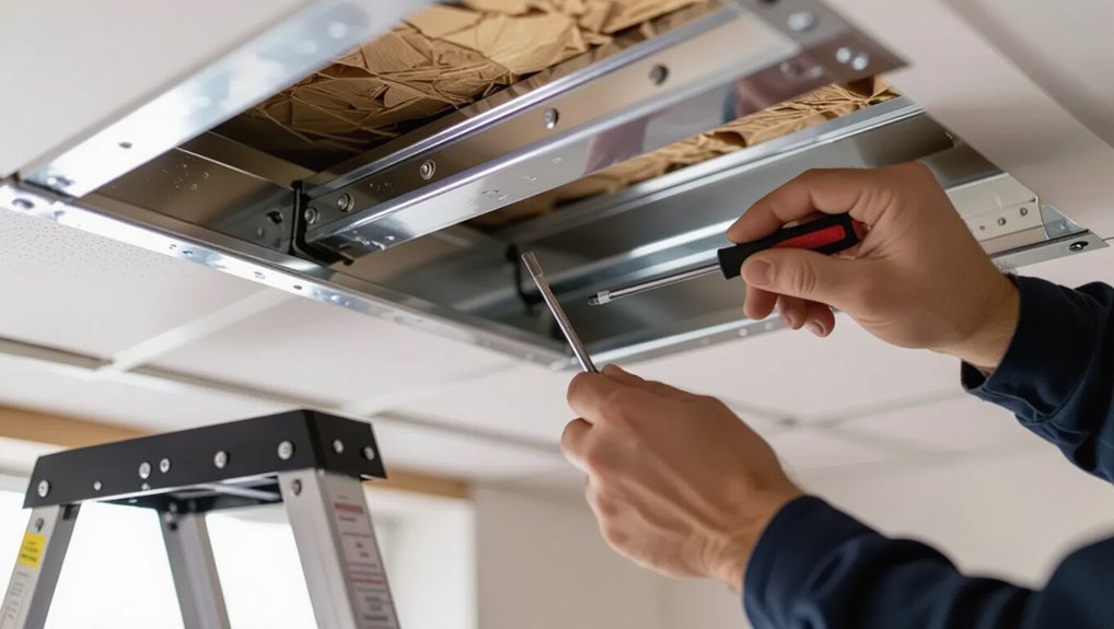
Balancing dampers regulate the volume and direction of airflow within an HVAC duct network to guarantee rooms receive the planned heating or cooling.
Signs of unbalanced ducts include persistent hot or cold rooms, unusual duct noise, and unexpectedly high energy consumption.
Before adjusting dampers, professionals should confirm safe ventilation, turn off equipment as needed, and be aware of combustion appliance and pressure-related safety issues.
How dampers control airflow in HVAC systems
Dampers regulate the volume and direction of air moving through ductwork by opening, closing, or throttling passageways to achieve desired airflow patterns and pressure balance.
Technicians modulate blade positions to direct flow, control zone temperatures, and reduce bypass.
Proper adjustment—learning how to adjust dampers in ducts—maintains system efficiency, prevents short-cycling, and balances supply and return air without altering fan speed or duct geometry.
Common signs of unbalanced ducts (hot/cold rooms, noise, high energy use)
When rooms consistently register different temperatures, produce unusual airflow noise, or drive up utility bills, the ductwork is often unbalanced and failing to deliver conditioned air where it’s needed; these symptoms indicate uneven pressure and flow that balancing dampers are designed to correct.
Other signs include persistent hot or cold spots, whistling or rattling in vents, short cycling of the system, and rising energy consumption.
Safety and ventilation considerations before adjusting dampers
Uneven temperatures, persistent noises, and rising energy bills signal that corrective action is needed, but efforts to adjust balancing dampers should not begin without attention to safety and ventilation.
Inspect system power, shut off fans or burners, and verify dampers are accessible. Confirm adequate fresh-air supply and carbon monoxide detectors; wear gloves and eye protection.
If ducts serve combustion appliances, consult a professional.
Tools and Materials Needed for Adjusting Dampers
Adjusting dampers requires a mix of basic hand tools and measuring instruments to set and verify airflow.
Essential items include screwdrivers, a tape measure, a thermometer, a balancing hood, and a manometer.
Optional precision tools such as an anemometer, airflow capture hood, and duct tape can improve accuracy.
Appropriate personal protective equipment and safe access equipment should be used whenever working in ducts.
Essential tools (screwdrivers, tape measure, thermometer, balancing hood, manometer)
Gather the right tools before opening any ductwork: a set of screwdrivers for damper screws, a tape measure for locating and marking dampers, and a reliable thermometer to check airflow temperature differences.
Also include a balancing hood to capture and quantify airflow at registers, and a manometer to measure static pressure and verify system balance.
Confirm calibration and proper connectors for accurate readings.
Optional tools for precision (anemometer, airflow capture hood, duct tape)
A few precision tools can sharpen damper adjustments: an anemometer for point airflow readings, an airflow capture hood for register-level volumetric measurement, and quality duct tape for sealing temporary leaks during testing.
Technicians use anemometers to verify velocity, capture hoods for accurate CFM per outlet, and duct tape to isolate leakage briefly.
These enhance measurement accuracy and speed without replacing basic tools.
Personal protective equipment and access equipment
Several essential pieces of personal protective and access equipment are required before working on duct dampers to confirm safety and reach.
Workers should wear safety glasses, gloves, hearing protection, and a dust mask or respirator as needed.
Use sturdy ladders or scaffolding, a flashlight or headlamp, and fall protection when elevated.
Verify PPE fits and access equipment is rated and inspected.
Preparing the System for Adjustment
Before adjusting dampers, the technician should choose the appropriate time for balancing, such as during seasonal changes or after new equipment or ductwork is installed.
Equipment must be powered down and zones isolated following safety procedures to prevent accidents and misleading readings.
Baseline airflow and temperature measurements should be recorded at each supply and return to guide and verify adjustments.
When to perform balancing (seasonal timing, after installations)
Timing is critical for effective duct balancing; it is best scheduled once the ventilation system is operating under typical conditions—usually in late spring and early fall when outdoor temperatures are moderate—or immediately after any significant change such as installing new equipment, replacing ductwork, or sealing leaks.
Perform balancing after occupancy patterns stabilize, post-maintenance, and following system expansions to guarantee measured airflow reflects real operating conditions.
Turning off equipment and isolating zones safely
Shut down affected HVAC units and isolate zones methodically to guarantee technician safety and preserve system settings; lockout-tagout procedures should be applied to electrical panels and control points, and dampers that will not be adjusted must be secured to prevent unintended movement.
Confirm isolation with control system indicators and physical verification, label isolated circuits and dampers, and communicate status to all personnel before proceeding with adjustments.
Establishing baseline airflow and temperature readings
Begin by documenting current system conditions to create a reliable reference point for adjustments: record supply and return temperatures, static pressure at key ducts, airflow CFM at each branch or diffuser using anemometers or pitot readings, and equipment status indicators such as fan speeds and damper positions.
Technicians should note ambient conditions, sensor calibration status, measurement locations, timestamps, and any anomalies before changing settings.
Step-by-Step Guide to Locating and Identifying Dampers
The guide outlines common damper types—manual, motorized, and volume control—and notes their distinct control mechanisms.
It explains typical placements in supply and return runs, at branch takeoffs, and near plenums or equipment connections.
It also shows how to read blade orientation and factory markings to determine open/closed positions and airflow direction.
Types of dampers (manual, motorized, volume control)
Dampers in duct systems come in several common types—manual, motorized, and volume control—each with distinct appearance and operation that technicians must recognize before adjustment.
Manual dampers use a simple lever or blade for hand positioning.
Motorized dampers employ actuators for remote or automated control.
Volume control dampers regulate flow precisely, often featuring graduated markings or multi-blade assemblies for fine balancing.
Where dampers are typically located in supply and return ducts
Locating dampers in a residential or commercial HVAC system requires a methodical sweep of both supply and return trunks, since they are most commonly found near the unit, at branch takeoffs, and adjacent to registers or grille collars.
Additional common locations include plenum assemblies, zoning panel connections, and access doors on main risers; smaller manual dampers may sit inside rectangular branches or behind ceiling grilles.
How to identify damper orientation and markings
Once a damper has been found, understanding its orientation and markings is essential to determine whether it is open, closed, or modulating.
Inspect blade position relative to airflow arrow stamped on housing; parallel blades indicate open, perpendicular indicate closed.
Note stamped or painted markings: OPEN, CLOSED, percentages, or detents.
Check handle or quadrant for stop screws and calibrated scales before adjusting to document baseline.
Step-by-Step Balancing Procedure for Manual Dampers
The technician first establishes target airflow for each room or register and records baseline measurements at every supply point.
Using incremental damper adjustments followed by airflow and pressure checks, the technician compares changes against targets and observes overall system response.
Once balanced, final damper positions are verified, then locked or marked to preserve the settings.
Establish target airflow for each room or register
Determine the target airflow for each room or register by calculating the required cubic feet per minute (CFM) based on room size, occupancy, and planned use.
Allocate CFM using standardized guidelines (e.g., ASHRAE recommendations) or proportional distribution of system capacity.
Document targets per register, noting temperature control priorities and any special ventilation needs to guide subsequent balancing adjustments.
Measure baseline airflow at each register
Begin by recording the existing airflow at every register to establish a clear baseline for balancing.
Using an anemometer or flow hood, measure and note CFM, temperature, and register location. Document multiple readings per register to average out fluctuations.
Include system status (fan speed, thermostat setting) and time of day. Preserve this baseline for comparison during subsequent adjustments.
Incremental damper adjustments and measurement checks
With baseline airflow documented, technicians proceed to incremental damper adjustments and measurement checks to balance the system.
Each damper is moved in small steps (e.g., 10–15%) while airflow at affected registers is remeasured.
Adjust one branch at a time, record results, and iterate until target flows are met.
Maintain notes for reversal and avoid simultaneous changes that obscure cause and effect.
Verifying pressure differences and system response
Verify pressure differences and observe system response by measuring static and differential pressures before and after each damper adjustment.
The technician records pressure changes at supply and return branches, notes airflow variations, and watches system stability.
Immediate effects and downstream impacts are compared to targets.
Adjustments continue until pressure differentials align with design criteria and transient responses remain acceptable.
Locking or marking final damper positions
After achieving target flows and stable pressures, secure the final damper settings to preserve system balance and facilitate future inspections.
Tighten locking screws or clamps and verify dampers remain at set angles.
Mark positions with paint, tags, or permanent markers and record numeric settings on system diagrams.
Note date, technician initials, and any anomalies for future reference and maintenance.
Balancing Procedure for Systems with Motorized Dampers and Zoning
Balancing systems with motorized dampers and zoning begins with grasping zoning controls and typical actuator responses to commands.
Technicians then calibrate each motorized damper through the control panel to guarantee commanded positions match physical travel.
Finally, they verify communication and actuator function, diagnosing failures with signal checks and manual override tests.
Understanding zoning controls and actuator behavior
Understanding zoning controls and actuator behavior is essential for achieving accurate airflow distribution when motorized dampers are used. These systems rely on coordinated signals from thermostats, a zone controller, and damper actuators to open or close dampers in response to load demands.
The technician verifies control logic, actuator response time, end‑stop settings, and feedback signals to guarantee reliable zone sequencing and prevent hunting.
Calibrating motorized dampers with control panels
Begin the calibration by placing the system in its normal operating mode and confirming each damper actuator is powered and communicating with the control panel.
Then command each damper to full open and full close to record travel limits.
Adjust endpoints in the panel, set midpoints or proportional positions per zone requirements, verify airflow readings, and save the configuration for automatic zoning sequences.
Troubleshooting communication or actuator failures
After endpoints and midpoints are set in the control panel, the technician should inspect communication links and actuator responses before proceeding with airflow balancing.
Verify wiring, network integrity, and power at each actuator. Command open/close cycles and confirm position feedback.
Replace faulty actuators, address protocol mismatches, and retest.
Document failures, corrective actions, and verify coordinated zoning operation prior to final balancing.
Using Measurement Tools Effectively
Effective use of measurement tools begins with anemometer readings at registers to quantify airflow and guide damper adjustments.
A manometer provides static pressure and pressure-drop data across dampers and components to confirm system balance and identify restrictions.
When readings are inconclusive or the system is complex, professional airflow hood testing should be engaged for certified measurements.
How to use an anemometer to measure register airflow
A handheld anemometer provides a quick, direct way to quantify airflow at a register, enabling precise damper adjustments and balancing decisions.
The technician centers the probe in the grille, records multiple readings across the face, averages them, and multiplies by grille area to calculate CFM.
Note airflow direction, stabilize readings, and compare against target values before altering dampers.
Using a manometer for static pressure and pressure drops
Measuring register airflow with an anemometer provides spot readings of volume, but understanding system performance requires pressure diagnostics. A manometer quantifies static pressure and pressure drops that reveal duct restrictions, filter loading, and fan performance.
The technician measures upstream and downstream pressures across components, records differential values, compares them to manufacturer or system targets, and uses results to prioritize damper adjustments and corrective maintenance.
When to call in professional airflow hood testing
When diagnostic readings from manometers and anemometers show inconsistent register flows, unequal room pressures, or unexpected pressure drops across branches, a technician should consider professional airflow hood testing to verify whole-system delivery.
Such testing provides calibrated volumetric measurements, identifies mis-sized ducts, bypasses, or balancing errors, and yields certified reports for compliance.
Call experts when self-measurement cannot isolate source discrepancies or meet code documentation needs.
Troubleshooting Common Problems During Balancing
Common balancing tasks can be disrupted by issues such as persistent hot or cold rooms after adjustments, excessive noise or whistling from dampers, and dampers that are stuck or inaccessible.
Technicians should also watch for inconsistent readings from instruments and apply systematic checks to identify measurement or airflow causes.
The following section outlines diagnostic steps and practical fixes for each of these common problems.
Persistent hot/cold rooms after adjustments
Persistent hot or cold rooms often indicate that initial damper adjustments did not fully correct airflow imbalances or that secondary issues are interfering with system performance.
Technicians should remeasure airflow, verify register and return openings, inspect duct leaks and insulation, confirm thermostat placement and calibration, and check for closed or obstructed vents.
Repeat incremental damper tuning until temperatures stabilize across affected zones.
Excessive noise or whistling from dampers
After rechecking airflow and sealing leaks to address hot or cold rooms, attention often turns to noise issues that can emerge during fine-tuning.
Excessive whistling or rattling usually indicates turbulent flow, misaligned blades, or loose hardware.
Inspect damper edges, tighten mounts, install foam or rubber gaskets, and slightly alter blade angle to smooth flow.
Re-test and adjust incrementally until noise subsides.
Damper stuck or inaccessible
When a damper becomes stuck or is located where access is limited, balancing efforts stall and pressure or temperature targets can’t be met.
Technicians should verify linkage, lubricate pivots, and clear obstructions. If unreachable, install remote operators or relocate dampers during planned maintenance.
Document inaccessible locations and use airflow measuring devices upstream and downstream to compensate until permanent access solutions are implemented.
Inconsistent readings and how to resolve them
Inconsistent airflow or pressure readings can undermine a balancing effort by producing unstable targets and repeated adjustment cycles.
Technicians should verify instrument calibration, stabilize sampling location, and allow system thermal and fan conditions to reach steady state.
Check for drafts, open doors, or intermittent dampers.
Use averaging or repeated measurements, log values, and retest after corrections to confirm consistent results.
Safety, Maintenance, and Long-Term Care
Routine checks and a seasonal rebalancing schedule help guarantee consistent airflow and catch emerging issues early.
Regular maintenance—tightening hardware, cleaning linkages, and lubricating moving parts—keeps dampers operating smoothly.
Replace worn or damaged dampers, or consider upgrading to motorized zoning, when repairs become frequent or precise control is required.
Routine checks and seasonal rebalancing schedule
Although dampers seldom require daily attention, scheduled inspections and seasonal adjustments are essential to maintain airflow efficiency and prevent wear.
Quarterly visual checks, airflow measurements, and zone comfort assessments detect drift or imbalance.
Perform thorough rebalancing at seasonal changes (spring, fall) or after HVAC modifications.
Document settings, readings, and corrective actions to track trends and plan professional service when persistent discrepancies appear.
Maintaining damper hardware and lubricating moving parts
Inspecting and maintaining damper hardware preserves system reliability and prevents costly failures.
Technicians should check linkages, screws, and blade edges for wear or corrosion, tighten fasteners, and replace stripped parts.
Apply recommended lubricant sparingly to pivots and bearings to guarantee smooth operation without attracting dust.
Verify free movement after service and document findings for future maintenance records.
When to replace dampers or upgrade to motorized zoning
When should a damper be replaced or a system upgraded to motorized zoning depends on performance, safety, and cost-effectiveness; signs that replacement is warranted include persistent air leaks, warped or corroded blades, seized linkages despite proper lubrication, or frequent balancing issues that manual dampers cannot correct.
Professional evaluation is advised for aging systems, inconsistent temperatures, or when automation improves efficiency, comfort, and controllability.
Cost, Time, and When to Hire a Professional
Typical DIY damper balancing can take one to three hours and cost mainly time plus a few dollars for basic tools and airflow meters, while professional services commonly charge a flat fee or hourly rate reflecting diagnostics and equipment.
Persistent pressure imbalances, unexplained hot or cold rooms, excessive static noise, or complex multi-zone systems indicate a need for professional HVAC balancing.
A professional service will perform measurements with calibrated instruments, adjust dampers and registers, report before-and-after readings, and recommend further repairs if necessary.
Typical time and cost estimates for DIY balancing
A basic DIY duct balancing job—adjusting a few registers and dampers in a single-story home—often takes 1–3 hours for someone with moderate DIY skills and basic tools.
More complex multi-zone systems or hard-to-access ducts can stretch to a half- or full-day.
Typical DIY costs range $0–$150 for tools and materials (thermometer, anemometer rental, sealant).
Expect potential additional parts expenses.
Signs that professional HVAC balancing is required
After attempting basic register and damper adjustments, some airflow or comfort problems persist beyond what a homeowner toolkit and a few hours can fix.
Persistent uneven temperatures, high energy bills, noisy ducts, or systems that short-cycle signal professional balancing is warranted.
Complex zoning, inaccessible ducts, or lack of improvement after DIY efforts justify hiring certified HVAC technicians who can diagnose, measure, and correct airflow.
What to expect from a professional balancing service
Many homeowners find that professional airflow balancing delivers measurable improvements in comfort and efficiency, but expectations should be set about cost, time, and the right circumstances for hiring a technician.
A typical visit includes assessment, measurements, adjustments, and a report; costs vary by system complexity and region. Typical duration ranges from 1–4 hours.
- Assessment and diagnosis
- Precise airflow measurements
- Targeted damper and register adjustments
- Final verification report
Quick Reference: Step Checklist for Balancing Airflow
A concise checklist helps guarantee duct dampers are adjusted efficiently and accurately.
It should cover pre-checks, a clear measurement-and-adjustment sequence, and final verification with documentation. Following a simple step-by-step list reduces errors and speeds up balancing.
- Inspect system readiness and tools before beginning
- Measure baseline airflow and note target values
- Adjust dampers in a logical sequence from main to branch
- Re-measure, record results, and label any changes
Pre-checks before starting
Before adjusting dampers, the technician should complete a concise checklist to assure safety and accurate measurements:
- verify power to HVAC components is off or locked out,
- confirm access panels and dampers are reachable,
- ensure appropriate PPE is worn,
- inspect ductwork for damage or obstructions,
- confirm tools and measurement devices are calibrated and charged,
- and note baseline thermostat settings and system run mode.
Measurement and adjustment sequence
With safety checks and baseline recordings complete, the technician proceeds to the measurement and adjustment sequence: establish a systematic order (typically from the air handler outward), measure airflow at each register using an anemometer or balometer, record readings, and compare them to target values for each zone.
Adjust dampers incrementally, re-measure after each change, prioritize critical spaces, and note deviations for follow-up.
Final verification and documentation
Complete the verification process by systematically confirming each register and damper setting against the recorded targets and noting any unresolved discrepancies.
The technician records final readings, signs off on deviations, and timestamps adjustments.
Photographs and annotated diagrams are saved alongside baseline measurements.
A concise report documents tools used, corrective actions taken, and recommendations for follow-up.
Retain records for maintenance and warranty purposes.
Comparison of Balancing Methods and Tools
Comparing balancing methods and tools requires evaluating accuracy, speed, cost, and suitability for the system size and complexity. The guide contrasts basic dampers, flow hoods, pitot tubes, and electronic balancers, noting trade-offs: simplicity versus precision, time investment, and budget. Selection depends on project scale and required measurement confidence.
| Tool | Accuracy | Best use |
|---|---|---|
| Damper check | Low | Quick fixes |
| Flow hood | Medium | Rooms |
| Pitot tube | High | Duct runs |
| Electronic balancer | Very high | Complex systems |
Conclusion
Properly balancing dampers in ducts guarantees even airflow and improved comfort, though some may worry it’s too technical. With basic tools and methodical steps, most homeowners can make meaningful adjustments safely; complex systems or persistent issues still warrant a professional. Regular checks and simple maintenance preserve results and efficiency. Ultimately, small, careful changes frequently yield noticeable improvements without costly equipment, blending practical DIY action with sensible limits and measured outcomes.