
How to Size a Gas Regulator: A Step-by-Step Guide to Choosing the Right Regulator for Your System
To size a gas regulator effectively, follow a systematic process that aligns the regulator’s capacity with your system’s peak appliance demand, inlet and outlet pressures, and any pressure drops in the piping. Start by identifying the type of gas you’re using, convert the required BTU/hr to SCFH, and account for all concurrent loads along with a safety margin. Choose a regulator that offers appropriate Cv values and is designed for single or two-stage operation based on supply variability. Ensure your installation meets layout, filtration, venting, and code compliance standards. Finally, conduct post-installation tests to verify performance. For further details on calculations, examples, and troubleshooting, refer to the complete guide.
How to Size a Gas Regulator: Quick Summary and Essential Outcome
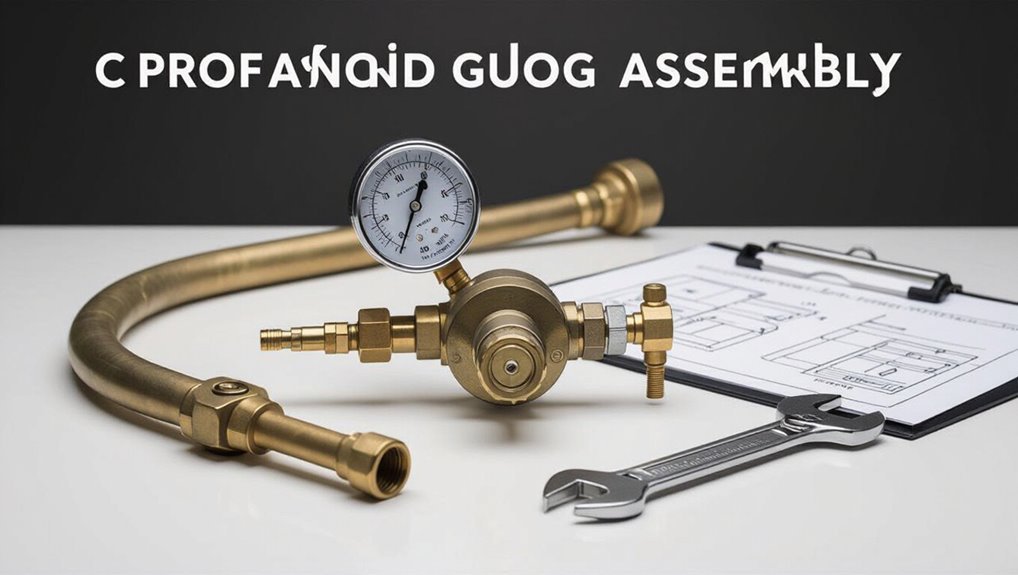
The article summarizes typical regulator recommendations for residential and light commercial systems, noting common sizes and capacities.
It highlights the essential numbers to verify immediately: inlet and outlet pressures and required flow rates.
These key checks determine whether a selected regulator will maintain stable pressure and meet peak demand.
Recommended regulator sizes for common residential and commercial systems
When sizing regulators for typical residential and light commercial installations, match regulator capacity to peak appliance demand measured in cubic feet per hour (CFH) or BTU/h, while keeping inlet and outlet pressure requirements and pipe sizing in sync to prevent pressure drop.
Guidance: small homes often use 3–10 psi low-pressure regulators (30–300 CFH); multi-family or small commercial require larger models (300–2000 CFH).
Key sizing numbers to check immediately (inlet/outlet pressures, flow rates)
A quick checklist of key numbers—upstream supply pressure, required downstream (set) pressure, and peak flow rate—determines whether a regulator will maintain safe, steady service under actual conditions.
Verify maximum inlet pressure, normal inlet, desired outlet/set pressure, and surge or continuous peak flow (SCFH or m3/h).
Confirm regulator capacity (Cv or flow curve) at those pressures and include margin for pressure drop and future demand.
Fundamentals of Gas Regulator Sizing
A gas regulator controls downstream pressure and flow, so selecting the correct size prevents underperformance, unsafe pressures, or excessive wear.
Common regulator types—single-stage, two-stage, pressure-reducing, and back-pressure models—are matched to applications from residential appliances to industrial burners.
Key units and terms to understand include inlet/outlet pressure, PSI/kPa, flow measures like SCFH and BTU/hr, and sizing parameters such as Cv.
What a gas regulator does and why correct sizing matters
Regulates pressure and flow, a gas regulator maintains a steady downstream pressure despite upstream fluctuations and variable demand.
Proper sizing guarantees sufficient flow, prevents pressure drop, avoids regulator hunting and premature wear, and maintains burner or instrument performance.
Undersized regulators starve equipment; oversized units can cause instability or slow response.
Correct selection optimizes safety, efficiency, and longevity of the gas system.
Common types of gas regulators and typical applications
Types of gas regulators vary by design and application, including single-stage and two-stage regulators for pressure control, direct-acting vs. pilot-operated for capacity and stability, and specialized variants such as line-pressure, cylinder, and appliance regulators for specific systems.
Selection depends on supply source, required flow, duty cycle, environmental conditions, and safety features.
Industrial, commercial, laboratory, and residential uses each favor particular styles for reliability and control.
Units and terms you must understand (PSI, kPa, SCFH, BTU/hr, Cv, inlet/outlet pressure)
Having established the common regulator styles and their typical uses, attention now shifts to the units and terms that govern sizing calculations.
Essential metrics include pressure (PSI, kPa), flow rates (SCFH), and heat load (BTU/hr).
Cv quantifies valve capacity. Inlet and outlet pressures define available drop.
Accurate conversion and consistent units guarantee correct regulator selection and safe, efficient system performance.
Gather System Inputs: What You Need Before Sizing
Before sizing a gas regulator, the engineer must gather key system inputs: gas type and properties, source pressure and its variability, and the piping layout.
Accurate demand data—either appliance/engine BTU ratings or required volumetric flow—is required to match regulator capacity.
Environmental and safety constraints such as altitude, ambient temperature, and applicable codes should be recorded to guarantee compliant selection.
Identify gas type and properties (natural gas vs propane/LPG)
Gas properties determine regulator selection and setpoint requirements: natural gas (methane-rich) and propane/LPG (propane or butane blends) differ in calorific value, specific gravity, inlet pressures, and combustion behavior, all of which affect flow capacity, pressure drop, and safety margins.
The designer must specify gas composition, Wobbe index, heating value, and density to choose compatible materials, pressure ratings, and relief settings for safe, efficient operation.
Measure or obtain supply conditions (source pressure, variability, piping layout)
Measure or obtain the supply pressure profile, its short- and long-term variability, and the physical piping layout feeding the regulator.
Record nominal source pressure, minimum and maximum excursions, cycling patterns, and any transient events.
Document inlet pipe size, length, fittings, valves, and elevation changes.
Note supply regulator locations, relief devices, and potential upstream restrictions that affect available inlet pressure and flow stability.
Determine demand: appliance/engine BTU or volumetric flow requirements
With inlet conditions documented, the next step is to quantify the downstream demand in either thermal (BTU/hr) or volumetric (SCFH/SLPM) terms for every appliance, burner, or engine the regulator will serve.
Collect nameplate ratings, manufacturer flow curves, and worst-case simultaneous usage.
Convert BTU to volumetric flow using gas heating value.
Sum peak and continuous demands to establish required regulator capacity.
List environmental and safety constraints (altitude, ambient temperature, codes)
Although often overlooked, environmental and safety constraints directly affect regulator selection and performance; they must be documented before final sizing.
Consider altitude (affects gas density and pressure drop), ambient temperature range (material and spring selection, freeze risk), corrosive or explosive atmospheres (certifications, materials), seismic or vibration exposure, ventilation, local codes and inspection requirements.
Document all constraints for compliant, reliable regulator choice.
Convert Loads to Flow Rates and Select Required Outlet Pressure
The procedure converts appliance or process loads (BTU/hr or kW) into gas flow rates (SCFH or m3/h) using gas-specific conversion factors and heating values.
It then identifies the minimum and maximum outlet pressures required by connected equipment and applies diversity factors to account for simultaneous use and planned expansion.
These calculated flow and pressure requirements form the basis for selecting an appropriately sized regulator.
Converting BTU/hr to SCFH or m3/h for common gases
Converting heating or process loads from BTU/hr into volumetric flow rates (SCFH or m3/h) is a necessary step in regulator sizing because regulators are specified by flow capacity and outlet pressure, not heat input. Using gas-specific heating values and conversion factors yields required SCFH or m3/h; add safety margin and sum concurrent loads before selecting regulator capacity.
| Gas | Conversion tip |
|---|---|
| Natural gas | Use 1,020 Btu/ft³ |
| Propane | Use 2,516 Btu/ft³ |
| Butane | Use 3,200 Btu/ft³ |
| Hydrogen | Use 325 Btu/ft³ |
Determining minimum and maximum outlet pressure required by equipment
With required volumetric flows established, the next step is to determine the minimum and maximum outlet pressures that the connected equipment needs to operate correctly.
Review manufacturer specifications for operating and start-up pressures, include any pressure drop across valves or filters, and note peak and idle requirements.
Specify safety margins and control tolerances so the regulator maintains pressure within required bounds under expected loads.
Accounting for diversity, simultaneous loads, and future expansion
Several factors must be reconciled when translating individual equipment demands into an aggregate flow rate and appropriate outlet pressure, including diversity of use, simultaneous operation, and anticipated expansion.
Apply diversity factors to reduce summed peak demands, model worst-case simultaneous loads for conservative sizing, and add allowance for foreseeable expansion.
Convert appliance ratings to standardized flow units and choose a regulator with margin for pressure drop and future capacity.
Calculate Required Capacity: Cv and Flow Curve Considerations
The discussion now turns to regulator capacity, beginning with Cv as the coefficient that quantifies how much gas will flow for a given pressure drop.
Using manufacturer flow curves, the required SCFH at the expected ΔP is matched to a regulator’s Cv to guarantee adequate delivery.
An example calculation for a 150,000 BTU/hr furnace illustrates estimating allowable pressure drop and selecting a regulator with the necessary Cv.
What Cv means and how it relates to flow through a regulator
Cv, or flow coefficient, quantifies a regulator’s ability to pass fluid by specifying the volumetric flow rate of water (in US gallons per minute) at 60°F that will flow through the device with a 1 psi pressure drop.
It translates to gas flow by adjusting for density and compressibility. Engineers use Cv to compare regulators, predict pressure drop for a given flow, and guarantee adequate capacity without oversizing.
Using regulator flow curves to match required SCFH at available pressure drop
Regulator flow curves translate Cv into usable performance data by showing how capacity (often in SCFH) varies with inlet-to-outlet pressure differential.
Reading them correctly lets an engineer verify that the device will deliver the required SCFH at the actual available pressure drop without relying solely on nominal Cv numbers.
Engineers plot required SCFH vs. ΔP on the curve, verify operating point lies below capacity line, and include margins for transient or mixed-gas conditions.
Estimating pressure drop across the regulator and allowable ΔP
When sizing a regulator, engineers first estimate the actual pressure drop available across the device and the maximum allowable ΔP to secure sufficient flow and stable control. This involves calculating pressure losses upstream and downstream (pipe friction, fittings, meters, control valves) and comparing the residual differential to the regulator’s required operating range.
They then verify regulator Cv, consult flow curves, and confirm margin for transient conditions.
Example calculation: sizing regulator for a 150,000 BTU/hr furnace
A practical example clarifies the steps: for a 150,000 BTU/hr natural gas furnace the engineer first converts heat input to volumetric flow.
Then, the engineer determines the regulator Cv required to pass that flow at the available pressure differential; this establishes whether a standard regulator or a higher-capacity model is needed and guides selection from manufacturer flow curves.
The calculation includes gas specific gravity, inlet pressure, and allowable ΔP to read Cv.
Matching Inlet Pressure and Regulator Stage Selection
Selection of single‑stage versus two‑stage regulators depends on inlet pressure stability and required outlet accuracy, with single‑stage suitable for steady, moderate drops and two‑stage preferred for large or fluctuating inlet pressures.
The regulator must be compatible with the expected inlet pressure range to maintain steady outlet regulation without exceeding design limits.
Material, connection type, and port sizing should be chosen for the specific gas, pressure, and installation to guarantee safety and reliable performance.
Single-stage vs two-stage regulators: when to choose each
Although both single-stage and two-stage regulators reduce cylinder or pipeline pressure to usable levels, matching the regulator type to inlet pressure stability and downstream demand is essential for safe, accurate gas delivery.
Single-stage units suit stable, low-to-moderate inlet pressures and simple applications.
Two-stage regulators provide superior outlet stability under fluctuating or high inlet pressures and critical processes, reducing sensitivity to upstream pressure decay.
Ensuring inlet pressure range compatibility and steady outlet regulation
Following the comparison of single- and two-stage regulators, attention turns to matching a regulator’s inlet pressure range with its stage design to maintain steady outlet delivery.
The designer verifies maximum and minimum source pressures, guarantees the regulator’s operating band accommodates expected fluctuations, and selects single-stage for narrow, stable inlet ranges or two-stage when wide or dropping inlet pressures require superior outlet stability and reduced creep.
Choosing material and connection types for the application
Materials and connection types must be chosen to withstand the gas chemistry, pressure, temperature, and service conditions while matching the regulator’s stage and inlet pressure characteristics.
Selection favors compatible metals or polymers, appropriate seals, and threaded, flange, or welded connections rated for operating pressure.
Corrosion resistance, leak tightness, maintenance access, and certification (e.g., ASME, ISO) guide final choices.
Piping, Upstream/Downstream Effects, and Installation Factors
Piping length, diameter, and the number of fittings directly influence available flow and pressure drop to the regulator and must be accounted for in sizing calculations.
Location, orientation, and mounting affect regulator performance, accessibility, and serviceability, so placement should minimize stress and allow proper venting.
Appropriate filters, shutoffs, relief valves, and venting provisions are required upstream and downstream to protect the regulator and system and to meet safety and code requirements.
How piping length, diameter, and fittings affect available flow
Many factors of the gas run—length, internal diameter, and the number and type of fittings—combine to determine available flow by increasing pressure drop between the regulator and appliances.
Longer runs and smaller diameters raise frictional losses; each elbow, tee, valve, or restriction adds localized loss.
Calculations use equivalent length or loss coefficients to size piping and select a regulator with sufficient flow capacity and acceptable downstream pressure.
Location, orientation, and mounting considerations
Regulator placement—whether mounted on a cylinder, wall, or equipment frame—directly influences performance and safety because upstream and downstream conditions change the effective inlet pressure, introduce potential vibration, and affect venting and access for maintenance.
Orientation affects diaphragm loading and condensate pooling; mountings must minimize stress, allow service clearance, and limit exposure to heat, corrosives, and mechanical impact to preserve set accuracy.
Need for filters, shutoffs, relief valves, and venting
Consider the full gas path when selecting filters, shutoffs, relief valves, and venting, since upstream contaminants, pressure surges, and downstream restrictions all alter regulator behavior and safety margins.
Proper filtration prevents particulate and liquid ingress. Shutoffs allow isolation for maintenance and emergencies. Relief valves protect against overpressure.
Adequate venting prevents trapped gas accumulation and guarantees predictable regulator response under varying flow and temperature conditions.
Practical Selection Workflow: Step-by-Step Checklist
A concise, practical checklist guides the regulator selection process through defined steps and verification.
Key actions include:
- Collect system data; convert loads to flow.
- Choose target outlet pressure and allowable ΔP.
- Select regulator Cv/model and verify piping and installation constraints.
A methodical progression through these items helps guarantee the chosen regulator meets performance and site requirements.
Step 1 Collect system data
Gathering accurate system data is the foundational task before any sizing calculations begin. The engineer documents gas type, inlet and required outlet pressures, maximum and minimum operating flows, temperature range, supply source characteristics, and pipe sizes/lengths.
Safety device setpoints, required response time, and environmental constraints are recorded. Verified, timestamped measurements and manufacturer datasheets guarantee reliable inputs for subsequent steps.
Step 2 Convert loads to flow
With system data compiled, the next task converts equipment loads and demand profiles into gas flow rates expressed in standard units (e.g., SCFH or Nm3/h).
Calculate steady, peak and intermittent demands per device, apply diversity or simultaneity factors, and sum flows for worst-case scenarios.
Convert between units using temperature and pressure corrections.
Document assumptions and margin for future expansion.
Step 3 Choose target outlet pressure and allowable ΔP
Clarity about the required outlet pressure and the permissible pressure drop (ΔP) is essential before selecting a regulator: specify the nominal outlet setpoint, minimum acceptable pressure under peak flow, and the maximum ΔP that downstream equipment can tolerate.
Document steady-state and transient requirements, surge margins, and any safety or control-loop constraints.
Record units and measurement points for verification during testing and commissioning.
Step 4 Select regulator Cv or model from manufacturer data
Begin matching the application requirements to manufacturer data by calculating the required valve flow coefficient (Cv) for the worst-case conditions and then using that Cv to narrow candidate regulator models.
Compare required Cv to published curves, account for gas properties, inlet pressure range, and allowable pressure drop.
Shortlist regulators whose performance envelopes cover worst-case flow with margin; note trim and setpoint options.
Step 5 Verify piping and installation constraints
Confirm that the selected regulator will fit both the physical layout and the hydraulic conditions of the installation by reviewing piping size, line length, upstream/downstream connections, elevation changes, and available inlet pressure under worst-case flows.
Check inlet/outlet thread types, orientation, and clearance for service.
Verify pressure drop budgets, support and anchoring requirements, and compatibility with nearby valves, filters, meters, and safety devices.
Step 6 Test, adjust, and document
With the regulator installed and piping verified, the next phase is functional testing, fine-tuning, and documenting the results.
Perform pressure and leak tests, verify setpoint stability under expected loads, and adjust downstream pressure and relief settings as needed.
Record test procedures, readings, serial numbers, and adjustments.
Include date, technician name, and follow-up actions to guarantee traceability and compliance.
Comparison of Popular Regulator Types and Performance
Different regulator types are compared by application pressure ranges, adjustability, and control method to match performance to system needs. The table below highlights a concise contrast between common categories to inform selection. Subsequent discussion will examine trade-offs in stability, flow capacity, and responsiveness for each type.
| Type Category | Key Consideration |
|---|---|
| Low-pressure vs High-pressure | Operating range and downstream application |
| Adjustable vs Fixed | Field tuning versus preset reliability |
| Direct-acting vs Pilot-operated | Response speed and capacity limitations |
| Selection Tip | Match type to required pressure range and flow characteristics |
Low-pressure vs high-pressure regulators
The distinction between low-pressure and high-pressure gas regulators hinges on their designated outlet pressures, flow capacity, and internal design: low-pressure regulators typically reduce cylinder or supply pressures to safe, usable levels for appliances and distribution systems (often under 15 psi).
In contrast, high-pressure regulators handle much higher downstream setpoints and greater inlet differentials for applications like industrial welding, gas boosters, or high-pressure storage.
Low-pressure units prioritize stability; high-pressure units emphasize robustness and leak tightness.
Adjustable vs fixed regulators
Many systems employ either adjustable or fixed gas regulators depending on whether variable control or simplicity and repeatable setpoints are prioritized.
Adjustable regulators offer field setpoint changes, fine-tuning, and broader application flexibility but require secure access and occasional recalibration.
Fixed regulators provide preset accuracy, tamper resistance, and quicker installation for standardized systems, reducing maintenance and risk of inadvertent adjustment.
Direct-acting vs pilot-operated regulators
After weighing adjustable versus fixed designs for setpoint control, attention shifts to how regulators manage flow and pressure dynamics: direct-acting and pilot-operated types represent the two primary approaches.
Direct-acting regulators respond quickly, suit low-to-moderate flow and simpler systems but exhibit higher droop.
Pilot-operated regulators offer superior stability, capacity, and accuracy for high flow or variable demand, though they are more complex and costlier.
Common Sizing Mistakes and How to Avoid Them
Common sizing errors often stem from underestimating simultaneous demand or future expansion, and from ignoring inlet pressure variability and resulting system ΔP.
Technicians also overlook line restrictions, fittings and their impact on flow, and sometimes fail to follow applicable codes or manufacturer recommendations.
Addressing these specific mistakes up front reduces the risk of undersized regulators and unsafe or noncompliant installations.
Underestimating simultaneous demand and future expansion
Overlooking the combined draw of multiple appliances and prospective load growth leads to undersized regulators that fail during peak use or impede future upgrades.
Designers should total concurrent maximum BTU or SCFH demands, include diversity factors only when justified, and add margin for foreseeable expansion.
Periodic reassessment guarantees capacity meets changes in equipment, usage patterns, or additional loads without costly retrofit or pressure loss.
Ignoring inlet pressure variability and system ΔP
When inlet pressure fluctuations and the resulting system pressure drop (ΔP) are not accounted for, a regulator can appear adequately sized during steady conditions yet fail to maintain required outlet pressure under real operating swings.
Designers must evaluate worst-case low inlet scenarios and dynamic ΔP during peak flow, selecting regulators with sufficient capacity, adequate droop tolerance, and appropriate relief or control features to preserve downstream performance.
Overlooking line restrictions and fittings
Neglecting the impact of valves, fittings, and narrow piping can severely degrade regulator performance by introducing additional pressure drop and flow turbulence that reduce available downstream pressure.
Engineers should quantify equivalent length and minor losses, verify sizing against actual piping layouts, and include restrictions in flow calculations.
Failure to account for these elements leads to undersized regulators, pressure starvation, and unstable operation; correct accounting prevents performance shortfalls.
Failing to follow codes and manufacturer recommendations
After accounting for piping losses and fittings, attention must turn to regulatory and manufacturer constraints that govern safe, reliable regulator selection.
Ignoring codes or installation instructions risks noncompliance, voided warranties, unsafe pressures, and liability.
Proper sizing must reference local codes, appliance manufacturer specs, and regulator documentation for inlet/outlet pressures, flow rates, venting, and mounting.
Document compliance and follow approved procedures.
Troubleshooting Performance Issues After Installation
After installation, the technician should systematically diagnose pressure drop, regulator hunting, and droop to identify root causes.
They should then apply corrective steps for under- or oversized regulators, such as adjusting inlet pressure, resizing orifices, or changing spring settings.
If problems persist under expected load, consideration should be given to adding a second stage or installing a larger regulator.
Diagnosing pressure drop, regulator hunting, and droop
Diagnose pressure drop, regulator hunting, and droop by systematically isolating the regulator and observing how inlet conditions, flow demand, and control components affect outlet pressure.
Record steady-state and transient pressures, vary flow incrementally, and note hysteresis or oscillation.
Check for clogged inlet filters, improper venting, pilot instability, or spring fatigue.
Correlate symptoms with operating maps to identify likely mechanical or system causes.
Steps to correct under- or oversized regulators
When a regulator is suspected to be under- or oversized, start by confirming actual operating conditions—measured inlet pressure, outlet setpoint, and flow profile—against the selection assumptions used during sizing.
Verify valve position and Cv utilization, check for obstructions or leak-induced demand, and confirm temperature effects.
If mismatch persists, adjust setpoint limits, replace with correctly sized unit, or recalibrate feedback controls to stabilize performance.
When to add a second stage or larger regulator
Consider upgrading the pressure-reduction stage if persistent outlet pressure drop, excessive regulator throttling, or repeated hunting cannot be resolved by cleaning, recalibration, or simple adjustments.
Evaluate system demand, inlet pressure stability, and flow capacity; install a larger single regulator or cascade a second stage to reduce drop, improve control bandwidth, and lower seat load.
Verify sizing with manufacturer curves and safety margins.
Safety, Codes, and Documentation Requirements
The installer should verify applicable codes and standards—ANSI, NFPA, and any local regulations—before finalizing regulator selection.
Required safety devices, clear labeling, and documented verification of setpoints and reliefs must be part of the installation.
Sizing calculations, test results, and ongoing maintenance records should be retained to demonstrate compliance and support future troubleshooting.
Relevant codes and standards to check (ANSI, NFPA, local)
A concise review of applicable codes and standards is essential before sizing a gas regulator to confirm safety, legal compliance, and system compatibility.
Relevant references include ANSI standards for pressure regulators, NFPA codes for fuel gas piping and equipment, and local building and utility regulations.
Consult manufacturer documentation and jurisdictional amendments, and verify inspection and permitting requirements to ascertain compliant installation and operation.
Required safety devices and labeling
Properly sized gas regulators must be accompanied by required safety devices and clear labeling to assure safe operation, facilitate maintenance, and meet regulatory obligations.
Required devices include relief valves, excess-flow shutoffs, pressure gauges, and isolation valves sized and rated to system pressure.
Labels must indicate set pressures, flow direction, fuel type, manufacturer, serial number, and inspection dates to guarantee compliance and safe service.
Keeping sizing calculations, test results, and maintenance records
Many facilities maintain thorough records of regulator sizing calculations, test results, and maintenance activities to guarantee traceability and regulatory compliance.
Documentation should include input data, calculation steps, calibration certificates, test dates, observed performance, corrective actions, and technician signatures.
Retention periods must follow codes and manufacturer recommendations.
Accessible, version-controlled records support audits, incident investigations, and informed replacement or recalibration decisions.
Supplier Selection and When to Consult an Expert
The author recommends asking manufacturers and distributors about flow capacity, pressure ratings, certification, lead times, and warranty details to verify product suitability.
They note a gas engineer or licensed contractor should be involved for complex installations, unusual fuels, high-pressure systems, or when local code interpretation is required.
Finally, the text emphasizes weighing upfront cost against performance, maintenance needs, and total lifecycle cost when selecting a supplier.
Questions to ask manufacturers and distributors
When selecting a supplier or deciding whether to consult an expert, engineers should prepare targeted questions that clarify regulator performance, compatibility, and support options.
Ask about certified inlet/outlet pressure ranges, Cv or flow curves, allowable gas types and temperatures, materials and certifications, turnaround for custom units, warranty and spare parts availability, calibration and testing procedures, technical documentation, lead times, and post-sale technical support.
When to involve a gas engineer or licensed contractor
How should professionals determine the need for a gas engineer or licensed contractor for regulator selection and installation?
They should engage qualified experts when systems involve high pressures, hazardous gases, complex piping, code compliance, or certification requirements.
Use contractors for final sizing verification, leak testing, commissioning, and where liability, permits, or insurance stipulate licensed installation.
Document qualifications and scope before contracting.
Cost vs performance trade-offs and total lifecycle considerations
Balance cost against performance and total lifecycle impact to guarantee regulator choices deliver reliable operation without hidden long-term expenses.
Decision-makers should compare upfront price, maintenance frequency, expected service life, energy efficiency, warranty terms, and spare parts availability.
Prioritize proven suppliers, consider total cost of ownership, and engage experts for complex systems to avoid underspecification or excessive overspending that compromises safety or uptime.
Conclusion
Proper gas regulator sizing prevents operational failures and safety incidents; studies show improper regulator selection contributes to roughly 30% of pressure-related system failures. By following systematic inputs—demand flow, inlet/outlet pressures, Cv, and appropriate safety margins—installers achieve stable delivery and reduced downtime. Attention to common mistakes, post-install troubleshooting, documentation, and code compliance closes the loop. When complexity or critical safety is involved, consulting a qualified supplier or engineer is strongly advised.