How to Remove Air From a Closed Loop System: Step-By-Step Bleeding and Maintenance Guide
To effectively remove air from a closed-loop system, follow these essential steps: depressurize and isolate zones, open vents at high points, briefly run the pump to dislodge air pockets, and top up the fluid to the correct pressure. Once steady liquid emerges from the vents, close them, cycle the zones, and monitor pressures and temperatures during a full system run. For detailed guidance and preventive maintenance tips, refer to the complete guide.
What a Closed Loop System Is and Why Air Is a Problem
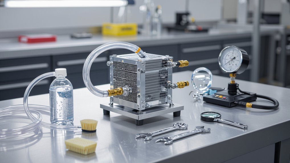
A closed loop system circulates a fixed fluid volume through pipes and equipment—common examples include hydronic heating, geothermal, chilled water, and vehicle coolant loops.
Air can enter these systems during installation, routine maintenance, through leaks, or as dissolved gases coming out of solution.
Trapped air causes noise, loss of efficiency, increased corrosion, and can lead to pump cavitation.
Definition and common types of closed loop systems (hydronic heating, geothermal, chilled water, coolant loops)
Closed-loop systems circulate a fixed volume of fluid through sealed piping and heat-exchange components so mass is conserved and external contamination is minimized.
Common types include hydronic heating, geothermal ground loops, chilled-water HVAC circuits, and engine or electronic coolant loops.
Understanding these applications is essential when learning how to remove air from a closed loop system, since component layout and bleed points vary by system type.
How air enters closed loop systems (installation, maintenance, leaks, dissolved gases)
Many closed systems acquire air through installation and service activities, small leaks, and gases coming out of solution as temperature or pressure change.
Air also enters via incomplete purging during commissioning, disturbed fittings during maintenance, permeation through hoses or seals, and cavitation-induced entrainment.
Dissolved oxygen and nitrogen release when fluids warm or pressure drops, introducing bubbles that migrate and accumulate in high points.
Consequences of trapped air (noise, reduced efficiency, corrosion, pump cavitation)
Trapped air in a closed loop system produces measurable performance and reliability problems: audible vibration and gurgling, reduced heat-transfer and flow efficiency, accelerated corrosion, and pump cavitation that can lead to premature failure.
These effects decrease system lifespan, increase energy use and maintenance costs, impair temperature control, promote oxidization and deposits, and cause erratic pump operation requiring repair or replacement if not promptly bled and prevented.
Quick Overview: How to Remove Air from a Closed Loop System
A concise checklist guides immediate actions: isolate the loop, relieve pressure, open bleed valves, and cycle the pump to purge trapped air.
Before starting, confirm lockout/tagout, wear eye and hand protection, and verify system temperature is safe to touch.
The following section expands on each step and the order to perform them safely.
Fast checklist for immediate action
Begin by shutting down the loop and isolating the system to prevent flow while preparing tools and safety gear.
Inspect vents, valves, and reservoir level.
Open designated bleed points starting highest to lowest.
Cycle pumps briefly to dislodge pockets.
Top up fluid to recommended level.
Close vents progressively, verify pressure stability, and run system to confirm absence of noise or visible bubbles.
Safety precautions before you begin
After completing the quick checklist and isolating the loop, attention turns to safety precautions before any bleed or pump cycling begins.
The operator should wear protective gear, depressurize slowly, verify electrical isolation, and confirm coolant compatibility.
Guarantee adequate ventilation, have spill containment and fire extinguisher ready, and keep bystanders clear.
Document valve positions and establish an emergency shutdown plan.
Tools and Materials Needed
A concise list of required tools and materials helps guarantee a smooth air-removal process in a closed loop system.
Basic hand tools (wrenches, screwdrivers, funnels) are complemented by specialized equipment such as automatic air vents, manual bleeder valves, a vacuum degasser, and a filling/flush cart.
Consumables and spare parts like inhibitor, replacement O-rings, and drain hoses should also be on hand before beginning.
Basic tools (wrenches, screwdrivers, funnels)
Several simple hand tools and a few small accessories are essential for bleeding a closed loop system safely and efficiently.
A set of adjustable and fixed wrenches fits various fittings; insulated screwdrivers adjust terminal screws and vents; flat and Phillips heads handle covers and clamps.
A narrow funnel and tubing facilitate controlled refilling. Gloves and rags protect surfaces and catch spills.
Specialized equipment (automatic air vents, manual bleeder valves, vacuum degasser, filling/flush cart)
Many systems benefit from a small set of specialized components—automatic air vents, manual bleeder valves, vacuum degassers, and a filling/flush cart—that speed and simplify air removal in closed loop circuits.
Automatic vents expel trapped air continuously; manual bleeders allow targeted purging.
Vacuum degassers extract dissolved gases for long-term stability.
A filling/flush cart enables controlled filling, circulation, and contamination removal during maintenance.
Consumables and replacements (inhibitor, replacement O-rings, drain hoses)
Once specialized components and filling equipment are in place, attention turns to the consumables and replacement parts that keep a closed loop system operational and leak-free.
Stock corrosion inhibitor compatible with system materials, spare O-rings and seal kits sized for fittings and valves, and durable drain/transfer hoses with fittings.
Include thread sealant, clamps, and labeled containers for safe handling and disposal.
Pre-Bleeding Preparation Steps
Before starting the bleed, the system is shut down and isolated following established procedures to prevent flow and electrical hazards.
Technicians identify vents, bleeder valves, and high points, then verify system pressure, temperature, and pump status to guarantee safe access.
Protective measures are put in place for sensitive components and appropriate containers are positioned to collect any drained fluid.
System shutdown and isolation procedures
Initiate a controlled shutdown of the closed-loop system to prevent pressure transients and isolate sections for safe bleeding operations.
Trained personnel follow documented lockout/tagout and shutdown sequences.
Depressurize slowly, monitor gauges, and record baseline readings.
Close isolation valves to segment the circuit and secure energy sources.
Verify system stability before accessing components for bleeding or maintenance.
Locating vents, bleeders, and high points
When preparing to bleed a closed-loop system, personnel should systematically identify all vents, bleeders, and high points by reviewing system schematics, tracing piping runs, and visually inspecting equipment.
Attention must be paid to expansion tanks, air separators, radiators, manifold headers, and the highest elevations in each circuit where air naturally accumulates.
Mark locations, note access requirements and valve states, and document orientation for safe, efficient venting.
Checking pressure, temperature, and pump status
Verify system pressure, temperature, and pump status to guarantee safe and effective bleeding: confirm system pressure matches design or operating targets, check temperatures at key locations to identify trapped air pockets or thermal stratification, and verify pumps are off or set to the required speed and direction per procedure.
Record baseline readings, compare to allowable ranges, and log pump electrical and mechanical status before starting.
Protecting components and collecting drained fluid
With pressure, temperature, and pump status recorded, attention turns to safeguarding system components and arranging fluid collection before bleeding begins.
Protective caps and heat-resistant covers are applied to sensitive fittings; electrical isolates prevent shorts.
Suitable containers and funnels collect drained coolant; absorbent pads and spill kits contain leaks.
Labels identify recovered fluid for proper disposal or reuse, minimizing contamination and environmental risk.
Step-by-Step Bleeding Procedure for Typical Hydronic/Heating Loops
The procedure that follows outlines the core steps for bleeding a typical hydronic heating loop and preventing trapped air from compromising performance.
It briefly lists preparatory actions, manual venting at high points, controlled topping-up of system pressure, and final pump cycling to purge remaining air. Technicians should follow the sequence methodically and monitor pressure and temperature throughout.
- Bring system to normal operating temperature, then shut off pumps and isolate zones as required.
- Open manual bleeder valves at radiators/baseboards/high points and use the fill/drain valve to top up system pressure slowly.
- Restart pumps and cycle zones to purge remaining air while watching for pressure stability and proper flow.
Step 1 Bring system to normal operating temperature
Bring the boiler and circulating pump up to the system’s normal operating temperature so trapped air expands and migrates toward high points and vents.
The technician verifies stable temperature, observes gauge readings, and listens for flow noise indicating movement.
Allow sufficient run time for thermal expansion, ensuring thermostats maintain setpoint.
Confirm pressure remains within normal range before proceeding to isolation or venting steps.
Step 2 Shut off circulation pumps (if required) and isolate zones
Shut off the circulation pump and close zone valves as needed to stop flow and isolate the section being bled.
The technician confirms pumps are de-energized and secures electrical locks where appropriate.
Isolation prevents air migration and protects other zones during bleeding.
Verify pressure gauges and thermostat settings remain stable; note valve positions for restoration.
Proceed only when isolation is confirmed.
Step 3 Open manual bleeder valves at radiators/baseboards/high points
Locate and open the manual bleeder valves at each radiator, baseboard, and any high points in the loop to allow trapped air to escape.
Use a small screwdriver or bleeder key, crack valves slowly until steady water appears.
Work systematically from the highest to lowest fixtures, collecting drips and closing each valve when air stops.
Note unusual sputtering indicating larger trapped pockets.
Step 4 Use fill/drain valve to top up system pressure slowly
Proceed to the fill/drain valve to slowly raise system pressure to the manufacturer’s recommended range (typically shown on the boiler boilerplate or loop documentation).
Open valve incrementally while monitoring the pressure gauge, pausing to allow trapped air to settle and bleed points to drip.
Stop when pressure is stable at target; close valve, recheck fittings for leaks and confirm gauge accuracy before proceeding.
Step 5 Restart pumps and cycle zones to purge remaining air
Restart the circulation pumps and sequentially cycle each zone valve to force water through the loop and mobilize trapped air.
Observe return lines and radiators for hissing or sputtering as air moves. Maintain pump operation briefly on each zone, then pause to allow air to collect at high points and bleeders.
Repeat cycles until audible air migration ceases and flow stabilizes.
Step 6 Close bleeders when water flows without air, recheck pressure
With audible air migration stopped and steady water flow observed at each bleeder, the operator should close each bleeder valve in order, starting from the lowest point and working toward the supply side.
After all bleeders are tightened, the operator rechecks system pressure at the expansion tank or gauge, topping off to specification if needed, and verifies no leaks at bleeder fittings.
Step 7 Monitor system and repeat if noise or pressure drops
Observe the system for at least one full heating cycle after bleeding to confirm stability: listen for new or recurring gurgling, monitor return and supply temperatures for unexpected swings, and watch the pressure gauge at the expansion tank or system connection for any drop.
If noise or pressure loss recurs, repeat targeted bleeding at affected zones, recheck valves and pump air traps, then retest until stable.
Bleeding Procedures for Specific Systems
The following section outlines tailored bleeding procedures for three common closed-loop applications: automotive/computer coolant systems, multi-zone chilled water HVAC loops, and ground-source geothermal loops.
Each system presents unique access points, preferred venting methods, and sequencing requirements that affect effectiveness and safety.
Readers are guided to apply the appropriate technique for system size, components, and operating pressures.
Bleeding a closed-loop coolant system (automotive/computer)
Begin by identifying whether the closed-loop system is automotive or computer-based, as each requires specific access points, tools, and safety precautions.
Then follow system-specific bleeding steps:
- Open designated bleed valves, reservoirs, or fill ports; run pump/engine to circulate.
- Expel trapped air via vents, tilting radiator/loop, and topping off coolant.
- Verify stable temperature and pressure; recheck for leaks.
Bleeding a chilled water HVAC loop (multi-zone commercial)
Many commercial chilled-water HVAC loops serving multiple zones require careful air removal to maintain flow balance, prevent noise, and guarantee efficient heat transfer.
- Isolate zones, run pumps at low speed, open high-point automatic air vents until steady water appears.
- Use zone valve sequencing and temporary bypasses to purge trapped air from coils and risers.
- Verify flow rates, listen for chatter, and retighten vents after stabilization.
Bleeding a geothermal loop (ground-source)
Purge air from a geothermal (ground-source) closed loop by establishing a controlled, low-pressure circulation that forces trapped gases toward high-point vents and the makeup reservoir.
- Isolate loop, open vent valves at manifolds and boreholes.
- Run pump slowly, monitor flow, watch venting until steady liquid appears.
- Top off reservoir, repressurize to design setpoint, check for pressure decay and noise; repeat if needed.
Using Mechanical and Automatic Degassing Devices
The section examines the function and placement of automatic air vents, explaining how they continuously expel trapped gas at high points and critical manifolds.
It also covers installation and operation of vacuum degassers and air separators for bulk and dissolved gas removal.
Guidance is provided on criteria for selecting manual bleeding versus automatic solutions based on system size, access, and maintenance considerations.
How automatic air vents work and where to install them
Automatic air vents and mechanical degassing devices expel trapped air from closed-loop systems by providing a controlled path for gas to separate and escape while keeping liquid contained.
Automatic vents use float-operated valves that open at air accumulation, sealing when liquid rises.
Install at high points, air pockets, near heat sources and pump inlets to prevent cavitation.
Regular inspection and accessible placement guarantee reliable operation.
Installing and operating vacuum degassers and air separators
Begin by selecting appropriate vacuum degassers and air separators sized to the system’s flow rate, pressure, and temperature. Then locate them at system high points and immediately downstream of heat sources, pumps, and boiler returns where dissolved and entrained gases concentrate.
Install per manufacturer instructions, include isolation and bypass valves, pressure/temperature monitoring, and guarantee proper vent routing.
Operate within rated limits and inspect periodically for performance and leaks.
When to choose manual bleeding vs. automatic devices
When system complexity, maintenance access, and sensitivity to downtime vary, choosing between manual bleeding and automatic degassing devices hinges on operational priorities and risk tolerance.
Manual bleeding is often suitable for small, low-pressure circuits with easily accessible vents and staff trained to perform regular purges.
On the other hand, automatic devices are preferable for larger, high-flow, or hard-to-access systems where continuous microbubble removal and minimal operator intervention are required.
Operators should weigh cost, reliability, and failure modes.
Detecting Persistent Air and Underlying Causes
Persistent air pockets often reveal themselves through localized noise and uneven temperatures, signaling that simple bleeding may be insufficient.
Technicians should then investigate potential leaks, corrosion, and water-quality problems as root causes rather than treating symptoms alone.
Standard diagnostics include pressure and leak testing plus measurements for dissolved oxygen and other impurities to identify and correct contamination sources.
Symptoms of stubborn air pockets (localized noise, temperature imbalance)
Several clear signs point to stubborn air pockets in a closed-loop system: localized gurgling or knocking, uneven temperature across radiators or heat exchangers, and intermittent loss of flow or pressure.
Additional symptoms include cold spots despite correct thermostat settings, sporadic pump cavitation noise, cycling pumps, and unexplained pressure fluctuations.
These indicators signal trapped air that reduces heat transfer efficiency and disrupts consistent circulation.
Diagnosing leaks, corrosion, and water quality issues
Localized noises and uneven temperatures often point beyond trapped pockets to underlying system health issues; diagnosing leaks, corrosion, and water quality helps determine why air keeps recurring.
Technicians inspect joints, valves, and radiators for hairline leaks, check for rust, pitting, and scale, and assess coolant condition and pH.
Addressing mechanical breaches and degraded inhibitors prevents reintroduction of air and system degradation.
How to test for dissolved oxygen and impurities
How can dissolved oxygen and particulate contaminants be measured to confirm whether recurring air pockets stem from water chemistry rather than mechanical faults?
Use calibrated dissolved oxygen meters or colorimetric kits to quantify O2; target near-zero values for properly treated systems.
Employ particle counters, turbidity meters, and filtration sampling with microscope inspection to detect solids.
Correlate results with pH, conductivity, and inhibitor concentration to identify chemical causes.
Maintenance Plan to Prevent Air Re-Entry
A concise maintenance plan outlines a regular inspection schedule with clear checkpoints for leaks, corroded fittings, and air-entraining components.
It specifies recommended water treatment and corrosion inhibitors to maintain system chemistry within safe parameters.
It also defines best practices for filling, pressurizing, and winterizing to minimize air re-entry during service and seasonal changes.
Regular inspection schedule and what to look for
Because small amounts of air can re-enter even a well-sealed closed-loop system over time, a defined inspection schedule is essential to catch early signs of ingress and prevent performance decline.
Quarterly visual checks, monthly pressure reviews, and immediate checks after system work are advised.
- Inspect fittings, valves, and gauges for leaks or corrosion.
- Monitor system pressure and expansion tank condition.
- Listen for gurgling, noise, or uneven flow.
Recommended water treatment and inhibitors
Maintain system chemistry with targeted water treatment and corrosion inhibitors to minimize air generation and entry in closed-loop systems.
Use pH buffers, oxygen scavengers, and film-forming inhibitors compatible with system materials.
Monitor inhibitor concentration periodically and adjust dosing to maintain protective levels.
Replace degraded treatment media and avoid mixing incompatible chemicals.
Document treatments and test for corrosion byproducts to anticipate maintenance.
Best practices for filling, pressurizing, and winterizing
Begin by establishing a disciplined filling and pressurization routine that guarantees systems are charged slowly, vented thoroughly, and held at correct static pressure to prevent trapped air and pressure-driven ingress during operation or shutdown.
Use calibrated gauges, follow manufacturer pressure targets, purge via high and low points, repeat cycles after thermal stabilization, add inhibitors, and winterize by draining low spots, isolating loops, and maintaining minimal positive pressure to deter air re-entry.
Common Mistakes and How to Avoid Them
Common mistakes during air removal often stem from improper pressure control, incorrect pump operation during bleeding, neglected vents at high points, and incompatible or unflushed treatment chemicals. Identifying and correcting these errors prevents recurring airlocks and system damage.
The following list highlights key pitfalls and preventative actions.
- Incorrect system pressure — avoid over-pressurizing or under-pressurizing by following manufacturer specs and using a calibrated gauge.
- Improper bleeding technique — never bleed with pumps running incorrectly; follow procedure for pump state and sequence.
- Maintenance oversights — routinely check air vents/high points and verify compatible inhibitors and full flushes when commissioning or adding fluid.
Over-pressurizing or under-pressurizing the system
Over- or under-pressurizing a closed loop system can quickly compromise performance and damage components; precise system pressure is essential for proper flow, heat transfer, and to prevent cavitation or seal failure.
Operators should verify manufacturer pressure specifications, use calibrated gauges, adjust expansion tanks and relief valves, and refill slowly while monitoring.
Regular checks prevent stress, leaks, and premature pump or seal wear.
Bleeding with pumps running incorrectly
Running a pump while attempting to bleed air from a closed loop system can mask problems, introduce new ones, and lead to ineffective purging if done incorrectly.
Operators may obscure trapped pockets, cavitate the pump, or force air into sensitive components.
Pause pumps during initial venting, use low flow when restarting, and monitor pressure and temperature to confirm complete air removal before full-speed operation.
Neglecting air vents and high points
Ignore air vents and high points at your peril: these are the natural escape routes for trapped gas, and failing to maintain or correctly place them leaves pockets that impair circulation and heat transfer.
Routine inspection, correct vent placement at system highs, and periodic manual venting prevent accumulations.
Neglect causes noise, reduced efficiency, and premature component wear; proactive maintenance preserves performance.
Using incompatible inhibitors or failing to flush new systems
Having addressed venting and high-point maintenance, attention must turn to the treatment and commissioning of the fluid itself.
Using incompatible inhibitors or failing to flush new systems causes corrosion, deposits, and persistent air entrapment. Properly flush pipework, remove debris, and select compatible, manufacturer-recommended inhibitors.
Verify concentrations, monitor pH/conductivity, and document commissioning to prevent chemical reactions that degrade seals and promote aeration.
When to Call a Professional
If air removal attempts do not stop persistent cavitation or the system involves complex multi-loop plumbing, a professional diagnosis is recommended.
The technician will need clear descriptions of observed symptoms plus photos showing pump locations, piping runs, valves, and any air vents or gauges.
Providing model numbers, recent maintenance history, and notes on noises or pressure fluctuations will speed accurate troubleshooting.
Signs that require expert diagnosis (persistent cavitation, complex multi-loop systems)
Recognize when common troubleshooting fails: persistent cavitation, unexplained pressure fluctuations, or erratic flow in multi-loop closed systems signal conditions that exceed routine DIY fixes.
Seek expert diagnosis when noise, recurrent air ingress, uneven loop balancing, or repeated pump failure persist despite proper bleeding.
Professionals evaluate system design, pressure transients, pump sizing, and hidden leaks using diagnostic tools and controlled tests.
What information and photos to provide to a technician
When problems persist despite basic troubleshooting, gathering clear, targeted information and photos will speed a technician’s assessment.
Document system type, model numbers, installation date, recent repairs, and exact symptoms (noise, pressure swings, temperature variance).
Photograph the pump, expansion vessel, bleed points, gauges with readings, visible air pockets, and piping layout.
Note steps already taken and timestamps to show recurrence and context.
Troubleshooting Quick Guides
The troubleshooting quick guides present common symptoms, likely causes, and immediate actions in a compact format to speed diagnosis. If a symptom persists after initial steps, clear escalation steps indicate when to recheck components, repeat procedures, or contact a technician. The table below summarizes symptom, probable cause, and next action for rapid reference.
| Symptom / Indicator | Suggested response |
|---|---|
| Pump noise or cavitation | Check loop pressure and bleed air at high points |
| Persisting temperature swing | Verify flow rate, inspect for trapped air, escalate if unresolved |
| Visible leaks or pressure loss | Tighten fittings, replace damaged parts, call a professional if pressure cannot be maintained |
Symptom vs. likely cause vs. immediate action
Although air in a closed-loop system can present with varied symptoms, a concise troubleshooting matrix linking each symptom to its most likely cause and an immediate corrective action greatly speeds diagnosis.
Examples:
gurgling—air pocket—bleed high points;
noisy pump—cavitation/low flow—check valves, purge;
fluctuating temps—partial blockage/air—flush and vent;
pressure loss—leak/air ingress—inspect seals, repressurize.
When symptom persists: escalation steps
Escalate methodically: if initial bleeding and basic checks fail to clear symptoms, progress through defined diagnostic tiers—repeat targeted venting and pressure verification, inspect for hidden air traps and restrictive fittings, perform flow-rate and temperature-differential measurements, then move to component isolation tests (pump, heat exchanger, valves).
Document findings, replace or bench-test suspect parts, verify system balance and fill procedures, and schedule follow-up monitoring to confirm resolution.
Appendix: Safety Checklist and Quick Reference Flowchart
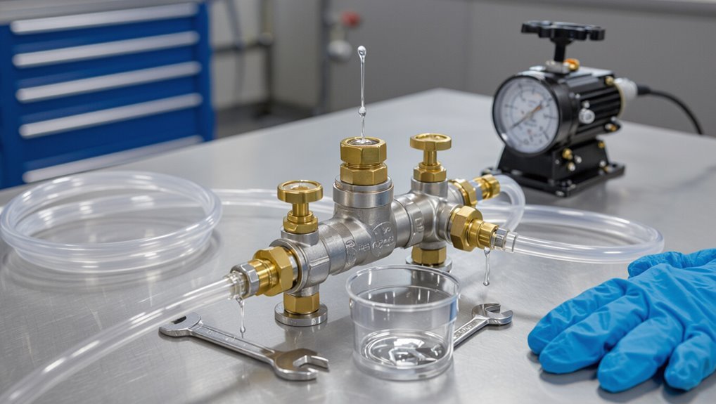
When preparing to purge or service a closed-loop system, personnel should follow a concise safety checklist and quick-reference flowchart to guarantee consistent, hazard-free procedures.
The appendix lists PPE, isolation, lockout/tagout, depressurization, venting points, and authorized personnel.
The flowchart outlines inspect → isolate → vent → bleed → verify pressure/stability → restore.
Emergency contacts and documentation steps conclude the checklist.
Conclusion
In conclusion, the guide closes the loop on keeping closed systems air-free, emphasizing regular bleeding, vigilance, and proper tools. Like a surgeon easing air from a patient’s veins, methodical steps protect performance and longevity. Small, routine actions stave off noise, corrosion, and inefficiency; persistent problems or complex systems warrant professional intervention. With safety checks and quick-reference routines in hand, system operators can maintain reliable, quiet operation and avoid costly failures.