
How to Fix “Pressure Switch Open” While Inducer Fan Runs: Step-by-Step Troubleshooting Guide
If you’re encountering a “pressure switch open” fault while the inducer fan is running, it indicates that the control board is not detecting a closed switch despite airflow. To troubleshoot this issue, follow these steps:
- Isolate Power: Always turn off power to the unit before beginning any work to ensure safety.
- Verify Inducer Voltage and Speed: Check that the inducer motor is receiving the correct voltage and is operating at the appropriate speed.
- Inspect Pressure Tubing: Look for any kinks or condensation in the pressure tubing that could impede airflow.
- Check Switch Terminals and Wiring: Test for continuity at the pressure switch terminals and inspect the wiring for any damage or loose connections.
- Confirm Vent and Condensate Paths: Ensure that both the vent and condensate paths are clear of obstructions.
- Replace Components if Necessary: If the pressure switch is corroded or appears weak, consider replacing it. Additionally, seal any leaks in the inducer housing.
By following these steps, you can effectively diagnose and resolve the “pressure switch open” issue. Always remember to prioritize safety throughout the troubleshooting process.
What “Pressure Switch Open” Means When the Inducer Fan Runs
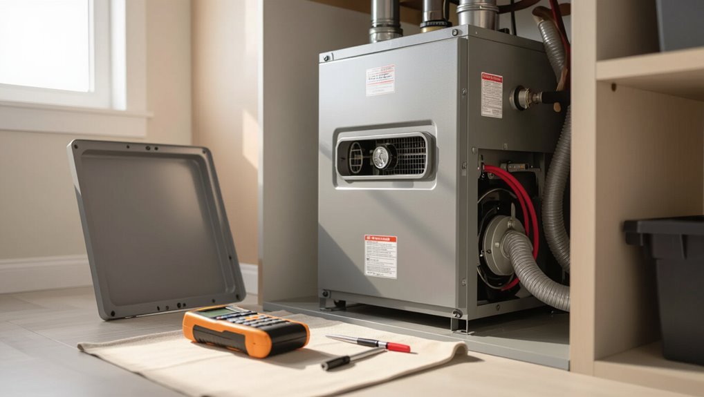
When a furnace displays a “pressure switch open” fault, it indicates the switch did not detect the required draft or differential pressure and the control board registers the circuit as open.
Seeing the inducer fan running while the pressure switch remains open is contradictory because the fan should create the negative pressure needed to close the switch; if it does not, the problem lies in the venting, tubing, switch, or switch actuator rather than the inducer itself.
This behavior is most commonly observed on mid- to high-efficiency direct-vent furnaces from many manufacturers, especially models that use a single-pressure-switch safety interlock.
Clear definition of the error and how it appears on furnaces
A pressure switch open fault indicates that the furnace’s safety circuit detects no switch closure despite the inducer fan running; in other words, the inducer motor has started but the pressure switch has not closed to confirm proper venting or airflow.
The error appears as a fault code, diagnostic LED pattern, or lockout; symptoms include failed ignition, repeated retries, and error logs.
Search term: how to fix pressure switch open with inducer on.
Why the inducer fan running while the pressure switch reads open is contradictory
Noting the inducer fan spinning while the pressure switch remains open highlights a clear contradiction: the inducer creates the airflow needed to develop the pressure differential that should close the switch.
So an open reading despite motor operation indicates a fault in airflow, the switch circuit, or the sensing pathway rather than a simple lack of power to the inducer.
This implies leaks, blockages, faulty switch contacts, tubing issues, or wiring faults.
Typical systems and models affected
Many common residential and light-commercial gas furnaces and boilers from major manufacturers will display a “pressure switch open” fault even while the inducer motor runs.
Recognizing which platforms are prone to this symptom helps narrow diagnostics.
Mid-efficiency, direct-vent and sealed-combustion units—especially older models from Carrier, Bryant, Trane, Rheem, Goodman and certain Bosch/Weil‑McLain boilers—commonly show this when venting, hose, switch or control board issues occur.
Quick Diagnosis Checklist (Immediate Steps to Take)
Before touching the furnace, the technician guarantees power and gas are shut off to prevent injury or ignition.
They then observe for visual and audible cues—such as inducer motor noise, tubing kinks, or a clicking pressure switch—to confirm component behavior.
Finally, they gather basic tools (multimeter, screwdriver, shop vacuum or compressed air, and replacement tubing) to proceed with targeted troubleshooting.
Safety first power and gas shutoff steps
When dealing with a suspected “pressure switch open” condition, the technician should immediately cut power to the furnace at the service switch and isolate the gas supply to prevent ignition while troubleshooting.
This guarantees a controlled environment for inspection and reduces the risk of electrical shock, fire, or accidental startup.
Confirm breaker off, tagout service switch, shut and cap manual gas valve if present, and ventilate area.
Visual and audible cues to verify inducer and switch behavior
A brief visual and audible inspection can quickly indicate whether the inducer motor and pressure switch are operating correctly.
Observe inducer spinning smoothly without wobble or smoke; note consistent RPM and no unusual screeching.
Listen for a soft click from the pressure switch when airflow develops.
Check for steady tubing connections and no visible obstructions or condensation pooling that might block pressure sensing.
Tools you’ll need for basic troubleshooting
Gather a small set of reliable tools to perform a quick diagnosis of a pressure-switch-open condition:
- a multimeter (for continuity and voltage checks)
- a small hand vacuum pump or bulb tester (to simulate inducer pressure)
- insulated screwdrivers and needle-nose pliers (for access and terminal handling)
- a flashlight
- replacement tubing or hose clamps for sealing checks.
Also include safety gloves, eye protection, and a notepad for readings.
How the Pressure Switch and Inducer Fan Work Together
The inducer motor creates the draft that supplies combustion air and safely vents combustion gases before the burner ignites.
The pressure switch, connected to the inducer by sensing tubing, detects the negative pressure the inducer produces and completes the circuit needed for ignition.
During startup the inducer runs first, the switch verifies sufficient draft, and only then does the control allow the burners to light.
Role of the inducer motor in combustion air flow
When the inducer motor spins, it creates a controlled draft that pulls combustion gases through the heat exchanger and draws fresh air into the burner assembly. This airflow produces the pressure differential the pressure switch monitors to confirm safe venting and proper combustion sequence.
The inducer’s speed, blade condition, and duct integrity determine flow rate and stability, affecting ignition reliability, heat transfer efficiency, and exhaust removal.
Function of the pressure switch and pressure sensing tubing
One key safety component is the pressure switch, a small electromechanical sensor that verifies the inducer fan has created the correct draft before ignition proceeds.
The switch monitors differential pressure via tubing connected between the inducer housing and manifold.
When tubing integrity and connections are intact, the switch closes on adequate vacuum; leaks, blockages, or misrouting prevent closure and signal a fault.
Normal sequence of operations during startup
Following confirmation that the pressure switch and tubing are intact, the furnace initiates a precise startup sequence to guarantee safe ignition.
The inducer motor starts, creating draft and differential pressure. The pressure switch senses the vacuum, closes its contacts, and signals the control board.
Upon confirmation, the ignition sequence begins, the gas valve opens, the burner lights, and the system shifts to normal operation.
Step-by-Step Troubleshooting Guide
The guide proceeds through a concise sequence of checks to isolate the cause of a “Pressure Switch Open” fault.
It begins by confirming inducer motor speed and electrical supply, then inspects pressure tubing for kinks or blockages and examines switch terminals and wiring for continuity and corrosion.
Finally, the switch is tested with a multimeter or manometer and venting/flue pathways are verified for obstructions or condensate buildup.
Step 1 Confirm inducer motor speed and electrical supply
Begin by verifying the inducer motor is running at the correct speed and receiving proper electrical supply, since inadequate RPM or voltage commonly causes a pressure switch to remain open.
Measure motor RPM or confirm expected frequency. Check incoming voltage at the inducer terminals under load with a multimeter.
Inspect wiring and connections for loose or corroded contacts and correct any discrepancies.
Step 2 Inspect pressure tubing for kinks, disconnections, or blockages
With inducer performance and supply confirmed, attention moves to the pressure tubing, a common source of open-switch faults.
Technicians should visually trace tubing from inducer to switch, looking for kinks, pinches, detachment, or debris.
Remove tubing ends, blow through gently to confirm flow, and replace brittle or collapsed sections.
Reattach securely with proper fittings before retesting the system.
Step 3 Check pressure switch terminals and wiring for continuity and corrosion
After confirming tubing integrity, attention turns to the pressure switch terminals and wiring to verify electrical continuity and detect corrosion that can mimic an open switch.
Power is isolated, terminals are visually inspected for green or white corrosion, loose screws, and broken insulation. Wires are gently tug-tested for secure connections.
Corroded contacts are cleaned or replaced; damaged wiring is repaired to restore reliable signaling.
Step 4 Test the pressure switch with a multimeter or manometer
To verify whether the pressure switch itself is functioning, the technician tests it using a multimeter for electrical continuity and a manometer for accurate pressure readings. These instruments together confirm whether the switch closes at the specified pressure and opens when pressure drops.
The technician isolates the switch, measures open/closed contacts during inducer operation, and compares manometer readings to manufacturer setpoint specifications.
Step 5 Verify venting and flue for obstructions or condensate buildup
While inspecting the venting and flue, the technician looks for blockages, collapsed sections, animal nests, and condensate accumulation that can impede airflow or trigger pressure-switch faults.
He clears obstructions, verifies proper pitch and joints, checks termination caps and screens, and guarantees condensate drains unobstructed.
If significant corrosion or persistent water pooling exists, recommend qualified replacement or repair to restore correct venting performance.
Step 6 Examine inducer housing and draft motor for leaks or gasket failures
Inspect the inducer assembly and draft motor for air leaks, damaged gaskets, and loose fasteners that can compromise pressure sensing.
Visually and manually check gasket integrity, mating surfaces, and blower seals. Listen for whistling or unusual airflow.
Tighten mounting bolts, replace deteriorated gaskets, and reseal small gaps with appropriate high-temperature sealant.
Confirm the inducer housing is square and free of corrosion or cracks.
Step 7 Replace or temporarily jumper the pressure switch (safety considerations)
Begin by de-energizing the furnace and verifying all power is off at the service switch and breaker to eliminate electrical and combustion risks.
Inspect the pressure switch for corrosion or failing contacts. Replace with an exact-match part if faulty.
For diagnostics only, a qualified technician may temporarily jumper the switch to confirm control board response, but never leave a jumper in place long-term due to safety hazards.
Step 8 Reassemble, restart, and observe for error recurrence
Carefully reassemble all furnace panels, reconnect any wiring or tubing removed during diagnostics, and restore power at the service switch and breaker.
Restart the furnace and allow a full heat cycle. Observe startup sequence, inducer operation, and control panel for the pressure switch fault.
Monitor for several cycles to confirm resolution; if the error returns, document symptoms and proceed to further diagnostics or professional service.
Common Causes Ranked by Likelihood
A ranked review of likely causes helps prioritize inspection when a “pressure switch open” fault appears. The most common issues tend to be airflow and pressure-path problems before electrical failures.
Technicians should check these items in order of likelihood to save time and avoid unnecessary parts replacement.
- Blocked vent or flue
- Cracked inducer housing or intake leaks
- Faulty or weak pressure switch
- Clogged, pinched, or disconnected pressure tubing
- Electrical faults: wiring, connectors, or control board issues
Blocked vent or flue
Many blocked vents or flues arise from debris, bird nests, ice, or collapsed ductwork that restricts exhaust flow and prevents the pressure switch from sensing proper draft.
Technicians should inspect terminations, vent runs, and flue connectors for obstructions, corrosion, or sagging.
Clearing blockages, repairing supports, or thawing ice typically restores draft.
Confirm proper pressure switch operation after remediation.
Cracked inducer housing or intake leaks
Inspecting the inducer assembly often reveals cracks in the housing or leaks at intake connections that allow air to bypass the pressure-sensing circuit, preventing the switch from seeing the required draft differential. Technicians should visually inspect seals, listen for whistling, and perform a smoke or soap test; repair or replace damaged components to restore airtight pathways and correct switch operation.
| Symptom | Test | Action |
|---|---|---|
| Whistle | Smoke test | Seal/replace |
| Noisy motor | Visual | Tighten clamps |
| Intermittent trips | Pressure probe | Repair leaks |
Faulty or weak pressure switch
Consider the pressure switch itself when troubleshooting persistent or unexplained open-switch faults: internal diaphragm wear, corroded contacts, or weakened springs are the most likely culprits.
A failing switch may not close despite correct inducer operation and proper tubing. Test continuity at specified vacuum, inspect terminals for oxidation, and replace the switch if calibration, responsiveness, or mechanical integrity are out of tolerance.
Clogged, pinched, or disconnected pressure tubing
Start by checking the pressure tubing for blockages, kinks, or disconnections, since restricted or interrupted airflow to the pressure switch is a frequent and easily overlooked cause of an open-switch fault.
Inspect tubing from inducer to switch for obstructions, pinches, cracks, or loose fittings. Clear debris, straighten bends, and reseat or replace damaged tubing.
Verify proper vacuum with a handheld gauge.
Electrical faults: wiring, connectors, or control board issues
If tubing appears sound, attention shifts to the electrical path between the pressure switch and the control system, where faults are a common cause of an open-switch indication. Technicians check wiring continuity, corroded connectors, loose terminals, and control board relay faults; intermittent opens often mimic sensor failure and require stepwise isolation and multi-meter verification.
| Component | Likely issue |
|---|---|
| Wiring | Breaks/shorts |
| Connectors | Corrosion/loose |
| Terminals | Poor contact |
| Control board | Faulty relay/electronics |
Condensate or debris in pressure sensing ports
Clogged pressure ports are a frequent and often overlooked cause of an open pressure-switch indication, especially in systems that produce condensate or operate in dusty environments.
Condensate, sludge, insect debris, or lint can block tubing or ports, preventing differential pressure sensing.
Inspect, blow out, or gently clear ports and tubing; replace degraded tubing.
Verify switch operation with a handheld vacuum or multimeter after cleaning.
Diagnostic Tests and How to Interpret Results
The technician begins by verifying switch continuity and circuit voltage with a multimeter to confirm electrical operation.
Differential pressure is then measured with a manometer, and smoke or visual leak tests are used to identify airflow breaches.
Control board diagnostics are considered when onboard error codes or logic checks contradict the sensor and pressure test results.
Using a multimeter to check switch continuity and voltage
Begin by powering off and unplugging the appliance.
Then set the multimeter to continuity (or ohms) to test the pressure switch contacts and to the appropriate DC/AC voltage range to check supply and control voltages.
Verify continuity across closed contacts when the inducer runs; open contacts indicate a switch fault.
Measure expected control voltage at harness terminals; absence or incorrect voltage points to wiring, relay, or control board issues.
Using a manometer to measure differential pressure readings
After confirming switch continuity and supply/control voltages with a multimeter, a manometer provides quantitative differential pressure readings to verify the pressure switch’s operating conditions.
Technicians connect the manometer across the switch tubing, run the inducer, and record inches of water column.
Compare measured rise and fall against manufacturer specs; deviations indicate blockage, tubing leaks, or a failing switch requiring targeted repair.
Smoke test and visual leak detection methods
Several simple diagnostic steps help pinpoint leaks affecting a pressure switch: a smoke test introduces visible tracer smoke into the pressure tubing and adjacent cavities while a technician watches for escaping plumes.
A careful visual inspection checks fittings, crimps, and hose runs for cracks, pinch points, or loose connections. Intermittent leaks reveal themselves under blower suction; seal suspect joints, retest, and replace brittle tubing.
When the control board diagnostics apply
Once tubing and fittings have been checked with smoke and visual inspection, attention shifts to whether the control board’s built‑in diagnostics should be used to confirm a pressure switch fault.
Technicians enable diagnostic mode to monitor switch open/close counts, pressure reading thresholds, and error codes.
If diagnostics show inconsistent closures or persistent open status despite correct vacuum, replace the switch or verify harness and board inputs.
When to Repair vs Replace Components
Clear indicators such as intermittent contacts, visible corrosion, or failure to actuate reliably point to pressure switch replacement rather than adjustment.
Similarly, an inducer motor showing excessive vibration, burned windings, or repeated start failures typically requires replacement, while minor noise or a faulty capacitor may justify repair.
Cost, expected remaining lifespan, and labor complexity should guide the decision, favoring replacement when parts are inexpensive relative to labor or when remaining service life is limited.
Signs a pressure switch should be replaced
Evaluate the pressure switch for specific, measurable signs that indicate replacement is necessary rather than repair. Persistent failure to close, visible corrosion, cracked diaphragm, or intermittent continuity despite correct venting are clear indicators. If tests show out-of-spec pressures or repeated failures, replace the switch to guarantee reliability.
| Sign | Implication |
|---|---|
| Won’t close | Mechanical failure |
| Corrosion | Electrical risk |
| Cracked diaphragm | Pressure leak |
| Intermittent continuity | Internal wear |
When inducer motor repair or replacement is warranted
Determine whether the inducer motor should be repaired or replaced by weighing measurable performance deficits, failure modes, and the cost-effectiveness of intervention.
Inspect bearings, shaft play, excessive vibration, noise, and electrical anomalies.
If faults are localized (worn bearings, loose connections) and parts are available, repair may suffice.
If windings, motor housing, or intermittent failure persist, replacement is warranted to restore reliable operation.
Cost and lifespan considerations for parts
Cost-benefit analysis guides whether a component should be repaired or replaced: compare the remaining useful life, parts and labor costs, and the risk of imminent failure. Evaluate age, warranty, failure frequency, and downtime impact. Prioritize replacement for high-failure risk or low-cost parts; repair when labor is low and life expectancy is adequate.
| Factor | Guidance |
|---|---|
| Age | Prefer replace if >75% life used |
| Cost | Replace if part <30% of unit cost |
| Failure risk | Replace for recurrent faults |
| Warranty | Replace if under warranty |
| Downtime | Replace to minimize outages |
Safety and Code Considerations
Bypassing a pressure switch or using jumpers can create serious safety hazards, including unvented combustion and fire risk, and should not be used as a permanent fix.
Local building codes and permit requirements may dictate what repairs are allowed by a homeowner versus those requiring formal inspection or documentation.
A licensed HVAC technician should be called for any uncertain diagnosis, code-related work, or when safe operation cannot be verified.
Risks of bypassing the pressure switch or using jumpers
Although a jumper can make a system appear to operate, defeating a pressure switch undermines essential safety interlocks and violates electrical and plumbing codes in many jurisdictions. Bypassing risks carbon monoxide exposure, fire, equipment damage, and voided warranties. Repair or replace the switch; never use jumpers. Consult a qualified technician for safe diagnostics and fixes.
| Risk | Consequence |
|---|---|
| CO leak | Life-threatening |
| Fire/equipment | Damage/warranty loss |
Local codes and permit considerations for furnace repair
When undertaking furnace repairs, compliance with local building codes and permit requirements is essential to confirm safety and legal operation.
Homeowners should verify jurisdictional rules before altering gas, venting, or electrical systems. Permits and inspections may be mandated for component replacement or modification.
Documentation secures liability protection and insurance validity.
Failure to follow codes can result in fines, unsafe installations, and denied claims.
When to call a licensed HVAC technician
How should a homeowner decide whether a pressure switch fault warrants DIY attention or requires a licensed HVAC technician?
The homeowner should call a licensed HVAC technician when diagnosis involves gas, electrical, sealed combustion components, complex venting, recurring faults, or when local codes require permits.
For simple checks—hose condition, condensate blockage, visible wiring—qualified DIYers may proceed; otherwise defer to a professional for safety and compliance.
Preventive Maintenance to Avoid Recurrence
Preventive maintenance reduces the chance of a “pressure switch open” fault by keeping vents, tubing, and the inducer functioning correctly.
A focused inspection checklist and a clear maintenance schedule help catch wear, blockages, and condensate issues before they affect the switch. Regular filter changes, condensate management, and targeted system upgrades complete a practical strategy to prevent recurrence.
- Inspect vent terminations and clear obstructions (birds, debris, ice)
- Check tubing for cracks, kinks, and secure fittings
- Verify inducer motor operation and listen for unusual noises
- Replace air and furnace filters on a set schedule; clear condensate drains
- Consider upgrades (sealed vents, modern switches, or condensate traps)
Routine inspection checklist for vents, tubing, and inducer
Because proper airflow and clear pathways are essential to furnace operation, a concise routine inspection checklist for vents, tubing, and the inducer focuses on verification, cleaning, and secure connections.
Inspect external vents for blockages, check flue and intake seals, examine PVC/condensate tubing for cracks or kinks, guarantee pressure switch hoses are seated and undamaged, and verify inducer blades spin freely without debris.
Recommended maintenance schedule and tasks
When scheduled at regular intervals, targeted maintenance tasks reduce the likelihood of a recurring “pressure switch open” fault by keeping airflow, electrical connections, and sensing components within operational tolerances.
| Interval | Task |
|---|---|
| Monthly | Inspect tubing for cracks and secure fittings |
| Quarterly | Verify switch continuity and terminal tightness |
| Annually | Clean inducer housing and blower wheel |
| Biannually | Calibrate or replace pressure switch as needed |
Filters, condensate management, and system upgrades
After establishing a maintenance cadence for tubing, switches, and inducer components, attention turns to filters, condensate management, and strategic system upgrades to further reduce “pressure switch open” incidents.
Replace or clean filters regularly, guarantee condensate traps and drains are clear and pitched correctly, install condensate pumps or float switches where needed, and consider upgraded pressure switches or inducer motors to improve reliability and fault tolerance.
Troubleshooting Scenarios and Case Examples
The following scenarios illustrate typical causes and observable signs when a pressure switch remains open.
Each case highlights specific symptoms, likely root causes, and practical checks to confirm the condition. Readers can use these examples to match symptoms on equipment and guide targeted troubleshooting.
- Inducer motor runs but vent blockage prevents negative pressure from reaching the switch
- Strong draft or debris visible at the vent termination during operation
- Intermittent fault codes tied to a visibly cracked or stressed pressure switch housing
- Switch contacts momentarily fail when the unit is jostled or vibrates
- Erratic fault resets caused by electrical noise or a control board misinterpretation
Scenario A Inducer runs but pressure switch never closes due to blocked vent
Several common furnace faults present as an inducer motor that runs while the pressure switch fails to close, often indicating a blocked vent or collapsed intake/exhaust pipe.
Technicians inspect vents for obstructions, verify condensate drains, and test differential pressure across the switch.
Cleaning, clearing bird nests, replacing crushed piping, or correcting vent routing typically restores proper pressure and allows the switch to close.
Scenario B Intermittent open switch from cracked housing
While a blocked vent commonly explains a pressure switch that never closes, intermittent open readings can point to internal switch damage such as a cracked housing.
Small cracks allow air leaks when vibrations or thermal cycling occur, causing sporadic failures.
Inspect the switch housing for hairline fractures, perform a smoke or soap-bubble leak test, and replace the switch if integrity is compromised.
Scenario C Electrical noise or control board misreading causing false fault
Consider electrical noise and control-board misreads when a pressure switch reports intermittent open faults despite a verified airtight system and a physically sound switch.
Investigate grounding, shared neutrals, and nearby high-current devices. Inspect wiring for chafing, loose terminals, and corrosion.
Swap or isolate the pressure switch circuit with a known-good harness. If noise persists, test or replace the control board and add suppression components as needed.
Parts, Tools, and Resources
A concise inventory of parts, tools, and reference materials helps streamline repair of a “pressure switch open” fault.
The following list highlights common replacement items, must-have diagnostic tools, and where to find authoritative documentation and support. Technicians and DIYers should match part numbers carefully and keep manufacturer resources on hand.
- Replacement pressure switches, diaphragms, and contact kits (with example part-number formats)
- Multimeter, clamp meter, insulated screwdrivers, and needle-nose pliers
- Small parts kit: wire nuts, crimp connectors, heat-shrink tubing, and fuses
- Manufacturer service manuals, wiring diagrams, and firmware/tech bulletins
- Official support links and contact channels for pump/pressure-switch manufacturers
Common replacement parts and part number tips
Several essential replacement parts commonly address a “pressure switch open” fault: the pressure switch itself, diaphragm or bellows assemblies, pressure tubing, fittings, and related relays or control modules.
Use exact model numbers from the furnace nameplate and OEM cross-reference charts. Match pressure range, electrical ratings, and connector types.
Keep tubing ID/OD and fitting threads consistent. Consider genuine OEM for reliability.
Essential tools for DIY diagnostics and repairs
After sourcing the correct replacement parts and verifying specifications, the next step is assembling the right set of tools and reference materials to diagnose and repair a pressure-switch-open fault safely and accurately.
Essential items include a multimeter, manometer or vacuum gauge, insulated screwdrivers, nut drivers, hose clamps, replacement tubing, contact cleaner, electrical tape, small mirror, flashlight, and a basic toolkit for furnace access and safe testing.
Recommended manufacturer documentation and support links
When consulting manufacturer documentation and support links for parts, tools, and resources, technicians should prioritize official installation manuals, wiring diagrams, replacement part catalogs, and service bulletins to guarantee compatibility and maintain warranty integrity.
They should also reference OEM troubleshooting guides, part number cross-references, technical support contact pages, and downloadable PDFs.
Bookmark model-specific pages and verify revision dates before ordering parts or following repair procedures.
Final Checklist Before Calling a Professional
Before contacting a technician, the homeowner should verify and document key items for the service visit, including photos of the unit, any visible wiring or damage, and written notes of recent events.
They should record error codes and collect test readings such as voltage, pressure, and continuity to share immediately.
A brief list of questions about likely causes, estimated steps for repair, parts required, and expected costs will help set clear expectations for the service call.
Items to verify and document for the technician
A concise checklist helps the technician diagnose a “Pressure Switch Open” fault quickly and accurately.
Verify model, serial, and installation date; note recent service or symptoms onset; confirm power status, thermostat calls, inducer operation, and error LED patterns.
Document visible hose condition, vent blockage signs, wiring integrity, fuse status, and any attempted fixes.
Record ambient conditions and safety concerns.
Photos, error codes, and test readings to collect
With the checklist items recorded, the technician should gather clear photos, any displayed error codes, and precise test readings to expedite diagnosis.
Photograph the inducer, pressure tubing, switch, control board, and labels. Record exact error codes and timestamps.
Capture multimeter readings: continuity, switch voltage under call, and vacuum/inch-H2O at the pressure tap.
Note ambient conditions and appliance model/serial.
Questions to ask and expected service steps
Which specific symptoms, test results, and prior repairs should the technician be briefed on before arrival?
Provide observed noises, error codes, voltages, manometer or multimeter readings, vacuum tube condition, and any cleared faults or component replacements.
Expect visual inspection, pressure tubing and switch continuity tests, inducer current/voltage checks, vent/chimney assessment, and targeted part replacement or adjustment with safety verification and system restart.
Conclusion
The guide leaves the reader better equipped to diagnose and often fix a “pressure switch open” fault when the inducer fan runs. By following logical checks and simple tests, one can separate minor issues from those requiring a pro, avoiding wasted time and expense. With routine maintenance and the right tools, many failures are preventable. When uncertain, though, it’s wise to swallow pride and call a qualified technician to guarantee safety and proper repair.
