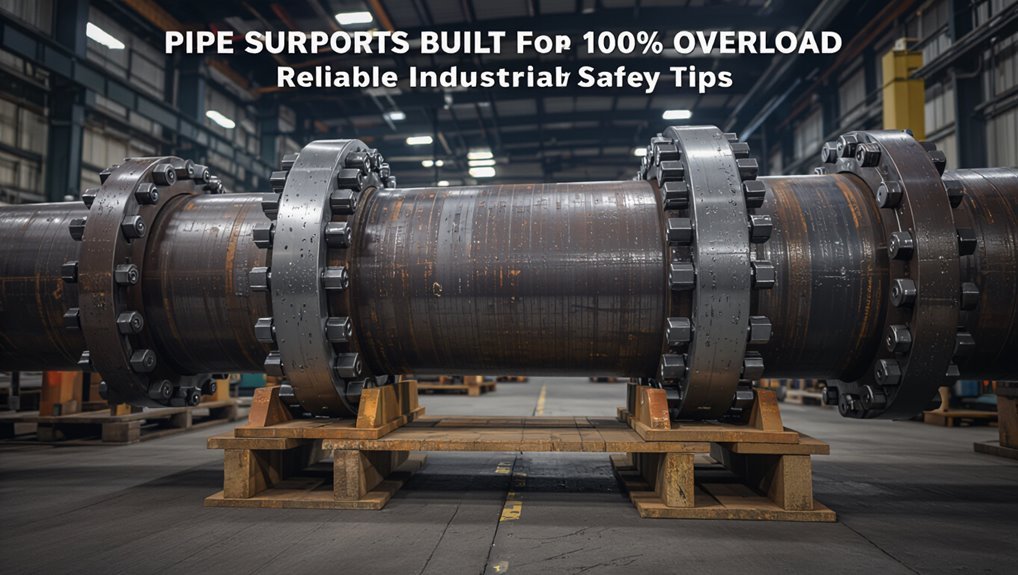
Pipe Supports Built for 100% Overload: Reliable Industrial Safety Tips
Pipe supports designed for 100% overload are essential for ensuring safety and reliability in industrial systems where transient forces, single-point failures, or hazardous materials may exert full-system loads. These supports are engineered by combining factors such as steady, thermal, wind, seismic, and accidental loads per code standards. This careful design process ensures that supports, connections, and materials are sized with conservative margins for maximum safety. Key practices in fabrication, galvanic compatibility, qualified welding, and meticulous installation are crucial for preserving load capacity. Regular inspections, calibrated load testing, and documented repairs guarantee that the system remains ready for operation. Additionally, analyzing common failure modes helps to implement corrective upgrades and redundancy. This document also provides practical checklists and procedures to support these efforts.
When to Require 100% Overload Capacity (Quick Decision Guide)
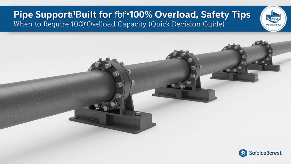
When should a pipe support be specified to carry 100% overload capacity? A decision guide favors 100% capacity when potential transient loads, credible abnormal events, or single-point failures could impose full-system forces.
Criticality of the service, hazardous contents, elevated temperatures causing restraint shifts, and long unsupported spans that amplify dynamic effects prompt this requirement. Where redundancy is limited or replacement access is restricted, specifying 100% overload reduces operational risk.
Inspection difficulty, regulatory mandates, and lessons from similar incidents also influence the choice. The criterion is applied selectively, focusing resources where failure consequences justify the added design conservatism.
Engineering Load Cases & Design Criteria for 100% Overload
In evaluating engineering load cases for 100% overload design, the focus is on identifying credible combinations of steady-state, transient, and abnormal forces that could impose full-system loads on a single support.
The engineering assessment quantifies service, thermal, wind, seismic, and accidental loads, then combines them per applicable codes to produce worst-case envelope conditions.
Material strengths, connection behavior, dynamic amplification, and load path integrity are checked.
Safety factors, inspection intervals, and maintenance access inform durability.
Designers document assumptions and validation methods, ensuring traceability and conservative margins consistent with plant risk profiles.
- Load identification and combination
- Structural capacity verification
- Documentation and inspection criteria
Support Types and Components Rated for 100% Overload (Selection Checklist)
Selection of supports rated for 100% overload begins with verifying load capacity ratings against the maximum static and dynamic forces expected.
Equally important is evaluating material and component compatibility to prevent galvanic corrosion, thermal expansion mismatch, or degradation under service conditions.
The checklist should consequently pair verified ratings with confirmed material compatibility before final specification.
Load Capacity Ratings
Many industrial pipe support systems are specified with a 100% overload rating to guarantee safety margins under unexpected load conditions. Load capacity ratings quantify static and dynamic limits, combining weight, thermal movement, seismic forces, and occasional impact.
Engineers verify rated capacities against calculated worst-case loads, applying safety factors, testing data, and manufacturer documentation. Regular reassessment makes certain ratings remain valid after modifications or operational changes.
Selection emphasizes clear documentation, traceable test certificates, and conservatively rounded capacities to avoid borderline use. Compliance with codes and coordination with structural assessments prevents overstress and preserves system integrity throughout service life.
- Verify rated static and dynamic limits
- Require test certificates and documentation
- Reassess after modifications
Material And Component Compatibility
For reliable 100% overload performance, materials and components must be compatible with each other and with the pipe system’s operating conditions.
Selection prioritizes corrosion resistance, thermal expansion coefficients, and mechanical strength to prevent differential degradation or failure under full-load events.
Fasteners, clamps, insulation, and pads should share galvanic compatibility and maintain rated strength at operating temperatures.
Elastomers require chemical resistance to conveyed media and retained elasticity over service life.
Welding, coatings, and sacrificial layers must not compromise structural margins.
Documentation of material properties, traceability, and inspection intervals completes the checklist for dependable, durable support assemblies.
Materials & Fabrication Practices to Achieve Overload Strength
In achieving overload strength, the choice of materials and disciplined fabrication methods determine whether a pipe support will withstand extreme loads without brittle failure or excessive deformation. Selection favors high-toughness steels, appropriate heat treatments, and corrosion-resistant alloys when environmental factors demand. Welding procedures follow qualified codes, minimizing residual stress and avoiding hydrogen embrittlement.
Fabrication tolerances guarantee load paths remain as designed; machining and fit-up prevent stress concentrators. Non-destructive testing and traceable material certification verify properties. Design allowances account for notch sensitivity, fatigue, and temperature effects, producing supports that retain integrity under single-event and repeated overload conditions.
- Material selection and certification
- Controlled welding and heat treatment
- Quality assurance and NDT
Installation Steps That Preserve 100% Overload Performance
A precise installation sequence preserves the overload performance verified during fabrication by ensuring load paths, alignments, and preloads are transferred to the structure without introducing damage or unintended restraint.
Installers follow engineered lifting points, support staging, and alignment fixtures to maintain geometry. Torque sequences for bolts and clamps match specified preloads. Isolation pads and shims are placed per drawing, avoiding field-modified lengths. Temporary supports bear loads until final anchorage is secured.
Welding, grinding, or drilling near critical members is forbidden. Movement joints are set to design clearances. Final adjustments use calibrated tools and only authorized personnel execute alterations to preserve certified capacity.
Inspection, Testing, and Documentation to Verify Overload Readiness
A structured visual inspection protocol establishes criteria for identifying corrosion, deformation, and fastening failures before load verification.
Controlled load tests are recorded with measured values, test setup descriptions, and pass/fail criteria to confirm overload readiness.
Combined inspection and load test documentation creates an auditable trail for maintenance decisions and regulatory compliance.
Visual Inspection Protocols
Regularly conducted visual inspections form the first line of defense in verifying pipe support systems are prepared for overload conditions.
Inspectors check welds, fasteners, hangers, and anchor points for corrosion, deformation, cracks, looseness, and misalignment.
Surface coatings and insulation are examined for deterioration that can hide defects.
Clear pass/fail criteria and photographic records support objective assessment.
Frequency follows risk-based schedules, increased after abnormal events.
Immediate tagging and isolation occur when deficiencies threaten load capacity.
Findings feed maintenance plans; critical items prompt expedited repair.
Training guarantees consistent identification and reporting.
- Check structural integrity and connections.
- Document defects with photos and criteria.
- Tag, isolate, and schedule repairs.
Load Test Documentation
Establishes a documented load-testing regime that verifies pipe supports perform as designed under expected and extreme loads, recording procedures, instruments, calibrations, applied loads, deflections, and observed behaviors.
Documentation includes test plans, acceptance criteria, and safety controls.
Calibrated gauges, load cells, and displacement sensors are logged with traceable certification.
Test execution records real-time data, stepwise load increments, hold times, and environmental conditions.
Deviations, anomalies, and repairs are noted with timestamps and responsible personnel.
Post-test reports summarize compliance versus design limits, residual deformations, and recommended corrective actions.
Archived records enable trend analysis, regulatory auditability, and lifecycle decision-making.
Common Failure Modes After Overload Events and Corrective Actions
Often overlooked after overload events, pipe support failures manifest in predictable ways that indicate specific corrective actions. Inspection should prioritize deformation, fastener damage, and corrosion that compromise load paths. Failure analyses guide targeted repairs, retrofits, or replacements and inform load redistribution and future design changes.
- Bent or yielded members: replace or cold-straighten when metallurgical integrity is intact; otherwise fabricate new supports and reassess design margins.
- Fastener and anchor failure: upgrade to higher-strength anchors, install redundancy, and verify substrate condition with pull tests.
- Corrosion-accelerated fractures: remove affected material, apply corrosion-resistant coatings, and implement cathodic protection where applicable.
Conclusion
Like a lighthouse standing firm through a storm, pipe supports built for 100% overload preserve system integrity when extremes occur. The guide emphasizes clear decision triggers, rigorous load-case engineering, proper material selection, and meticulous fabrication and installation. Regular inspection, testing, and documentation confirm readiness, while understanding common failure modes enables swift corrective action. Together, these practices guarantee reliable, code-compliant supports that protect personnel, equipment, and operations under worst-case conditions.