How to Fix a Sprinkler Solenoid: Step-by-Step DIY Troubleshooting and Repair
To fix a faulty sprinkler solenoid, start by cutting power and relieving line pressure. Diagnose the issue by checking the controller output and measuring the coil resistance with a multimeter. Inspect the solenoid and plunger for corrosion or debris; clean and lubricate if they are salvageable. If the solenoid is burnt or shorted, replace it with a matching-voltage coil. Next, verify the wiring, apply dielectric grease to connections, and run manual tests to ensure proper operation. Follow the detailed step-by-step repair guide for specific parts and preventive tips.
How to Fix a Sprinkler Solenoid Quickly: What to Know Before You Start
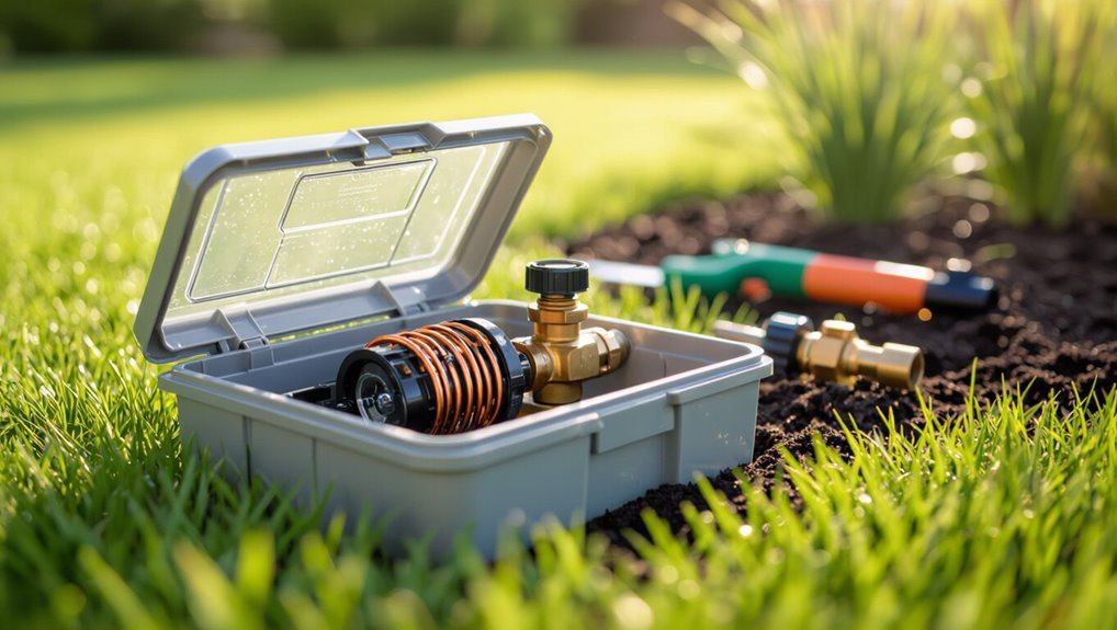
Before beginning, the article lists common signs that point to a faulty solenoid—such as zones that won’t start, valves that stay stuck open, or a humming coil with no operation.
It then outlines basic safety steps and the small set of tools usually required, including turning off power and water before any work.
Finally, it explains clear criteria for when a homeowner can attempt a quick repair and when to call a professional for diagnosis or replacement.
Signs the solenoid is the problem (symptoms to check)
When a sprinkler zone fails to open or closes unexpectedly, the solenoid is often the first component checked. Recognizing specific symptoms—such as a valve that hums without activating, a zone that stays on constantly, or erratic on/off cycles—helps isolate the issue quickly.
Other signs include no response from the controller, visible corrosion or water inside the solenoid casing, and unusual electrical readings when testing how to fix a sprinkler solenoid.
Safety precautions and tools required
A few basic safety steps and the right tools greatly reduce risk and speed diagnosis; technicians should shut off the controller and isolate power at the irrigation transformer or breaker, confirm circuits are de-energized with a multimeter, and relieve line pressure by manually operating a zone or closing the main shutoff.
Essential items include:
- Multimeter, insulated screwdrivers, wire cutters
- Replacement solenoid, waterproof connectors, Teflon tape
- Work gloves, safety glasses, flashlight
When to call a professional vs. DIY
Having confirmed power is isolated and the right tools are on hand, the decision whether to proceed or call a professional rests on scope, skill, and risk.
DIY is appropriate for simple coil swaps, visible wiring repairs, or solenoid replacements when comfort with basic tools exists.
Call a pro for complex valve bodies, persistent electrical faults, buried pipe damage, warranty concerns, or lack of time and confidence.
Quick Diagnostic Steps to Isolate Solenoid Issues
Before testing, power and water should be shut off safely and the system isolated to prevent damage or injury.
The technician then checks for electrical output at the controller and valve, uses a multimeter to measure solenoid resistance and continuity, and records any anomalies.
Finally, simple bypass tests—energizing the valve directly or swapping solenoids—help confirm whether the problem lies with the solenoid, the valve, or the controller.
How to shut off power and water safely
Cut power to the irrigation controller and close the main water valve before testing any solenoid components, ensuring electrical and hydraulic isolation to prevent shocks and unintended flow.
Verify controller is off and label circuits to avoid accidental reactivation.
Shut off any nearby auxiliary valves, depressurize lines by opening a downstream drain, and use insulated tools.
Confirm visual isolation before proceeding.
Testing for electrical power at the controller and valve
With power and water confirmed off and lines depressurized, the next step is to verify whether electrical signals reach the controller and valve.
Inspect wiring for corrosion, loose connections, and damaged insulation.
Restore power briefly to run a manual station cycle at the controller while observing voltage at the valve plug or terminal block.
Note whether the controller emits clicks and whether any wires heat or spark.
Using a multimeter to test solenoid resistance and continuity
Begin by setting a multimeter to the ohms (Ω) scale to measure the solenoid’s resistance and continuity; this provides a quick, reliable indication of whether the coil is intact or open-circuited.
Disconnect power, remove leads from the solenoid, and probe the two terminals.
Compare the reading to manufacturer specs (typically 20–60 Ω for many valves).
Infinite or very high resistance indicates a failed coil.
Bypass tests to confirm the valve and solenoid behavior
Perform simple bypass tests to determine whether the issue lies with the solenoid, the valve body, or the controller by manually activating components and observing direct responses.
Manually open the valve plunger or use a 9V battery on the solenoid leads to force activation.
Then apply a known working controller output to the valve.
Note immediate response, lag, or no movement to isolate fault.
Step-by-Step Solenoid Repair and Replacement
The procedure begins by removing the valve box cover to expose the solenoid and documenting each wire connection before disconnecting.
The solenoid is then inspected for visible damage or corrosion, cleaned and reassembled if stuck, or replaced if beyond repair.
When replacing, the correct replacement part is selected to match the valve type and electrical specifications.
Removing the valve box cover and exposing the solenoid
To access the solenoid, the technician lifts the valve box lid and clears away debris until the control assembly and individual valves are fully visible.
Next, remaining soil and roots are brushed aside, taking care not to disturb nearby piping.
The solenoid’s position on the valve bonnet is identified, and any surface grime is wiped clean to allow clear inspection and straightforward subsequent work.
Disconnecting wiring and labeling connections
With the valve bonnet exposed and surface grime cleared, attention turns to the electrical connections securing the solenoid. The technician identifies common wire colors, photographs the layout, then disconnects power at the controller before loosening terminal screws.
Label each conductor to preserve wiring order and prevent miswiring during reassembly.
- Photograph connections for reference
- Mark wires with numbered tags
- Secure loose ends safely
Inspecting the solenoid for visible damage or corrosion
Begin by closely examining the solenoid for cracks, breaks, rust, mineral buildup, or loose components that could impede function.
Note corrosion at terminals, frayed or exposed wiring, and warped plastic or metal parts. Photograph damage for reference.
Determine whether corrosion is superficial or structural; heavy pitting, broken windings, or compromised seals typically indicate replacement rather than repair.
Cleaning and reassembling a stuck solenoid
Carefully disassemble the solenoid assembly, keeping parts organized and noting their orientation for reassembly.
Clean coil, plunger, spring, and core with a soft brush and isopropyl alcohol; remove mineral deposits and debris.
Lightly lubricate moving surfaces with silicone-based lubricant.
Reassemble in reverse order, ensuring the plunger moves freely and seals align.
Test for smooth operation before reinstalling.
Replacing the solenoid: selecting the correct replacement part
When a solenoid proves beyond cleaning or repair, the technician should identify a correct replacement by matching electrical specifications, physical dimensions, and valve compatibility to guarantee reliable operation.
Confirm voltage (12V/24V), coil resistance, and plug type. Measure thread size, mounting style, and plunger length.
Verify manufacturer cross-references or model numbers and choose water-resistant materials to secure durability and fit.
Rewiring and testing the new solenoid
Disconnect power and label wires before connecting the replacement solenoid to confirm correct polarity and circuit continuity.
Reattach wires using waterproof connectors or heat-shrink crimps, matching colors and terminals.
Restore power briefly to test valve actuation, listening for click and observing water flow.
If operation fails, recheck connections, coil resistance with a multimeter, and verify controller sends the correct zone signal before sealing the assembly.
Common Solenoid Problems and How to Fix Them
Common solenoid issues include burned or shorted coils, clogged plungers, corroded wiring or connectors, and problems with valve diaphragms or seats that mimic solenoid failure.
Technicians diagnose a burned coil with a multimeter and replace it if resistance is out of range. They clear dirty plungers with a soft brush and mild cleaner, and repair corroded connectors by cleaning or replacing damaged wiring.
They also compare actuator response to valve seating to distinguish diaphragm or seat faults from true solenoid malfunctions.
Burned or shorted coil diagnosis and remedy
Several clear signs indicate a sprinkler solenoid coil is burned or shorted, and prompt diagnosis prevents further valve damage.
The coil may smell of burning, feel hot, show melted insulation or soot, or fail continuity on a multimeter.
Replace the coil with the exact replacement, verify correct voltage and wiring, and retest the valve.
Inspect for water ingress causing shorting.
Clogged or dirty plunger cleaning technique
Begin by removing the solenoid assembly and inspecting the plunger for mineral buildup, debris, or corrosion that can impede movement.
Clean gently with a soft brush and pick, rinsing in vinegar or a mild descaler to dissolve deposits.
Dry thoroughly, lubricate lightly with a non-petroleum silicone grease, reassemble, and test for smooth, free travel before reinstalling.
Corroded wiring and connectors repair methods
Inspecting corroded wiring and connectors is essential because electrical resistance or intermittent contacts can prevent a sprinkler solenoid from operating reliably.
Technicians should disconnect power, remove corrosion with a wire brush or contact cleaner, trim and re-strip damaged wire, and replace terminals or use heat-shrink butt connectors.
Test continuity and secure connections; apply dielectric grease to slow future corrosion and reassemble.
Valve diaphragm or seat issues vs. solenoid issues
How can one tell whether a sprinkler zone is failing because of a worn valve diaphragm or seat rather than a solenoid fault?
The technician inspects flow: slow opening, constant drip, or inability to hold pressure suggest diaphragm/seat wear.
Removing the solenoid and manually lifting the plunger isolates solenoid function.
Visible tears, debris, or hardened rubber confirm diaphragm/seat replacement rather than solenoid repair.
Troubleshooting Related Valve and Controller Issues
A malfunctioning controller can produce the same symptoms as a bad solenoid, so controllers and wiring should be checked before replacing parts.
Technicians should also evaluate zone valves for mechanical faults, debris, or broken diaphragms that are independent of the solenoid.
Finally, verifying solenoid-compatible voltage and testing the transformer output helps distinguish electrical supply issues from component failure.
How a faulty controller can mimic solenoid failure
Controllers can produce symptoms indistinguishable from a bad solenoid by failing to send the correct voltage, timing, or signal to the valve, leading technicians to misattribute the problem to the solenoid itself.
Faulty controller outputs, intermittent zones, programming errors, or damaged terminal strips can prevent valve activation.
Verify controller voltages, run manual station tests, inspect wiring continuity and connectors before replacing solenoids.
Diagnosing zone valve problems that aren’t solenoid-related
Many zone issues stem from components other than the solenoid—wiring faults, debris-clogged diaphragms, worn seals, or malfunctioning controller outputs can all prevent a valve from operating properly.
Inspect wiring for breaks or corrosion, manually lift diaphragm to test flow, clean or replace clogged screens, and examine seal integrity.
Confirm controller scheduling and output sequencing before replacing valve assemblies.
Solenoid-compatible voltage and transformer checks
Several common solenoid failures trace back to incorrect voltage or a faulty transformer rather than the coil itself.
Technicians measure controller output, confirm coil rating (24V typical), and test transformer under load. If readings diverge, replace the transformer or adjust controller settings to match solenoid specs.
- Verify controller terminal voltage.
- Check coil resistance and rating.
- Test transformer under load.
Parts, Tools, and Materials Checklist
A concise checklist helps guarantee the repair proceeds smoothly by specifying compatible replacement solenoids and their voltage/current ratings.
It also lists essential tools and spare parts to keep on hand, such as multimeters, pliers, wire nuts, and O-rings.
Optional upgrades like corrosion-resistant solenoids or quick-connect fittings that improve long-term reliability are also noted.
Recommended replacement solenoids and specifications
Choosing the correct replacement solenoid guarantees reliable valve operation and prevents repeat failures; consequently, match the solenoid’s voltage, thread size, flow orientation (normally open vs. normally closed), and coil enclosure rating to the existing system and local conditions. Recommended choices include 24VAC irrigation coils, common 3/4″ NPT or 1/2″ BSP threads, epoxy-coated enclosures, and compatible plunger lengths.
| Feature | Recommendation |
|---|---|
| Voltage | 24VAC |
| Thread | 3/4″ NPT |
| Orientation | Normally closed |
| Enclosure | Epoxy sealed |
| Plunger | Standard length |
Essential tools and spare parts to keep on hand
With replacement solenoids matched to system specs, technicians should prepare a compact kit of tools and spare parts to enable rapid on-site repairs. Essentials include replacement solenoids, O-rings, and a basic multimeter.
Additional handy items and tools:
- Small screwdrivers, pliers, and wire strippers
- Waterproof connectors, spare wire, and heat shrink
- Silicone lubricant, cleaning brushes, and replacement diaphragms
Optional upgrades to improve reliability
Although not strictly necessary for basic repairs, a small set of targeted upgrades can markedly improve long-term solenoid reliability. Technicians should consequently consider adding higher-grade components and diagnostic tools to their kit.
Recommended upgrades include stainless-steel or brass replacement plungers, sealed weatherproof solenoids, higher-quality diaphragms, quick-connect waterproof wire connectors, a handheld multimeter with continuity and inductance, and a spare solenoid manifold for rapid field replacement.
Preventive Maintenance to Extend Solenoid Life
A regular inspection schedule helps detect worn seals, loose wiring, and mineral buildup before they cause failure.
Proper winterizing and corrosion prevention—such as draining lines, applying dielectric grease, and using protective coatings—significantly reduce seasonal damage.
Correct installation practices, including proper torque on fittings and secure electrical connections, prevent many common premature failures.
Regular inspection schedule and what to look for
Because routine checks catch wear before failures escalate, a scheduled inspection cadence is essential for extending sprinkler solenoid life.
Inspect monthly during the season: check coil integrity, wiring connections, valve body for leaks, plunger movement, and debris in ports.
Record findings, note irregular operation or slow response, and replace seals or coils showing corrosion or diminished performance.
Maintain a log for trend tracking.
Best practices for winterizing and corrosion prevention
Following monthly inspections and logged observations, attention should turn to winterizing and preventing corrosion to preserve solenoid function through cold months.
Drain lines and blow out zones to remove residual water, disconnect and store removable solenoids indoors, apply dielectric grease to electrical connections, protect exposed metal with corrosion-inhibiting spray, and inspect seals.
Reassemble in spring after checking insulation and continuity.
Tips to avoid common installation mistakes
When installing sprinkler solenoids, attention to correct wiring, proper seating, and compatible components prevents most premature failures.
Installers should torque fittings, align diaphragms, and use dielectric grease on electrical connections.
Verify valve orientation and flow direction, match coil voltage, and secure conduit to avoid strain.
Test cycles before backfilling, document configurations, and replace damaged parts immediately to prevent recurring faults.
Quick Troubleshooting Flowchart and Decision Guide
A concise troubleshooting flowchart lays out stepwise decision points to quickly isolate whether the problem is electrical, hydraulic, or mechanical.
Each branch should include an estimated time and a difficulty rating so readers can choose the appropriate repair path.
This approach helps prioritize simple fixes and identify when professional help is warranted.
Stepwise decision points to isolate the issue
Begin by isolating whether the problem is electrical, mechanical, or related to water flow. Then progress through a short sequence of yes/no checks that quickly narrow the fault to one component.
Inspect power at the controller, solenoid continuity, and valve movement. Follow these concise steps:
- Is controller sending power? yes/no
- Does solenoid read continuity? yes/no
- Does plunger move freely? yes/no
Estimated time and difficulty for each repair path
If the quick checks point to a specific component, the guide assigns each repair path an estimated duration and difficulty level so users can prioritize fixes:
simple coil replacement — 15–30 minutes, easy;
cleaning contacts or debris — 10–20 minutes, easy;
replacing valve plunger/seal — 30–60 minutes, moderate;
rewiring or replacing the controller — 45–120 minutes, moderate to difficult;
diagnosing intermittent electrical faults — 60–180 minutes, difficult.
Real-World Repair Scenarios and Solutions
The section presents three common repair scenarios with step-by-step solutions: intermittent zone activation, a zone that never opens, and an electrical short triggering controller errors.
For each scenario, the technician is guided through systematic tests, component swaps, and wiring checks to isolate the fault.
Clear resolution steps and typical causes are provided so readers can apply the appropriate fix.
Scenario: Intermittent zone activation stepwise fix
Troubleshooting an intermittently activating zone requires a systematic, step-by-step approach to isolate whether the issue stems from wiring, the controller, or the solenoid/valve assembly itself.
First, run manual tests at the controller and at the valve. Inspect and wiggle wiring for breaks or corrosion. Measure voltage during activation.
Swap the solenoid with a known good one. Replace faulty components and retest for consistent operation.
Scenario: Zone never opens systematic troubleshooting
Begin by confirming that the controller is sending a signal and the valve is receiving power: test with a multimeter at the valve terminals.
If voltage is present, inspect the solenoid for continuity and replace faulty coil.
Manually lift the diaphragm; if flow occurs, clear debris or replace diaphragm.
Check inlet shutoff, clogged filter, and frozen or broken pipes before concluding valve assembly replacement.
Scenario: Electrical short causing controller error resolution steps
Isolate the controller and inspect wiring for signs of charring, exposed conductors, or loose connections before powering the system.
If damage exists, cut power, document terminal assignments, and replace burned wire or terminal blocks.
Test each zone with a multimeter for shorts to ground.
Repair insulation, tighten connections, and restart controller.
Monitor for errors; if persistent, consult a licensed electrician.
Final Testing and Verification Before Closing Valve Box
After repair, the technician runs both manual and automatic station tests to confirm the solenoid and valve operate correctly.
They inspect for leaks, verify wiring and connectors are secure, and monitor cycles for a short period.
Finally, the technician records the actions taken, parts replaced, and test results for future reference.
Running manual and automatic tests to confirm repair
With the solenoid reinstalled and wiring secured, testing proceeds through a sequence of manual and automatic checks to verify proper operation before sealing the valve box.
The technician actuates the valve manually at the controller, observes prompt opening and closing, then runs an automatic zone cycle to confirm timing, response, and consistent activation across cycles.
Any anomalies prompt reinspection and retest.
Verifying no leaks and secure wiring
Begin a visual and tactile inspection of the valve assembly to verify there are no leaks and that all wiring remains secure before closing the box.
Check fittings, solenoid seals, and pipe joints for dampness or drips.
Gently tug each wire to establish solid connections and proper insulation.
Replace damaged connectors, tighten loose clamps, then re-run a quick cycle to confirm stability.
Documenting the repair for future reference
Having confirmed no leaks and secure wiring, the technician should create a concise record of the repair and final test results before closing the valve box.
Note date, solenoid model, parts replaced, wire connections, multimeter readings, and any adjustments made.
Photograph wiring and component placement.
Store notes with system documentation or digitally for quick retrieval during future maintenance or warranty claims.
Conclusion
Clear, concise conclusions can crystallize complex conclusions: careful checks, clean connections, and correct component changes culminate in consistent coverage. Methodical maintenance minimizes malfunctions, making many messy moments manageable. Troubleshooters testing tools, toggling terminals, and trusting trim techniques terminate tedious trials. Replacing rusted regulators, reseating seals, and restoring reliable routing returns systems to regular rhythms. Diligent diagnostics, deliberate decisions, and documented do-overs deliver durable, dependable distributions of water and peace.