
How to Find a Refrigerant Leak in AC: Step-by-Step Detection and Fix Guide
To find a refrigerant leak in your AC, start by inspecting coils, fittings, valves, and service ports for signs like oil stains, corrosion, frost, or hissing sounds. Ensure you wear appropriate safety gear before conducting a thorough visual inspection of both indoor and outdoor units. Use a soap solution on joints to detect bubbles, and consider using an electronic leak detector, UV dye, or a nitrogen pressure test for hidden leaks. While temporary seals may offer a short-term fix, brazing or replacing components is recommended for a lasting solution. Follow this guide for detailed steps on detection, repair, costs, and prevention.
What Causes Refrigerant Leaks in Air Conditioners
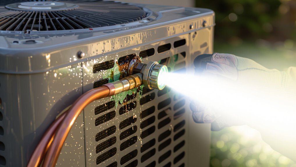
Refrigerant leaks most often originate at coils, fittings, valves, and service ports where seals and joints can fail.
Corrosion, vibration, and physical damage weaken components and create pathways for refrigerant to escape.
Reduced cooling performance, hissing or bubbling sounds, ice on lines or coils, and unusual odors commonly indicate a leak.
Common leak sources (coils, fittings, valves, service ports)
Although routine wear and corrosion gradually weaken system components, most leaks originate at a few predictable spots: evaporator and condenser coils, pipe fittings and brazed joints, service valves, and access ports.
Technicians checking how to find refrigerant leak in ac focus on coil seams, soldered connections, Schrader cores, valve stems and threaded service ports.
Detection targets tight joints and visible oil traces.
Corrosion, vibration, and physical damage as root causes
Corrosion, vibration, and physical impact account for the majority of AC refrigerant leaks by progressively weakening metal, seals, and joints until they fail.
Corrosion from moisture, salt, or chemical exposure thins tubing and corrodes brazed joints. Continuous vibration loosens fittings and work-hardens metal.
Physical damage from tools, debris, or mishandling punctures lines or stresses connections, creating slow or sudden leaks that escape detection.
Signs a leak is present (performance, sounds, ice, odour)
When an air conditioner begins losing refrigerant, several clear indicators usually appear: diminished cooling performance and longer run times as the system struggles to reach set temperatures, hissing or bubbling noises from pressurized lines and components, frost or ice buildup on evaporator coils and refrigerant lines, and occasionally a chemical or sweet odor near indoor units or service panels.
Technicians also note reduced airflow, higher energy use, and frequent short cycling.
Quick Risk Assessment Before You Start
Before attempting any leak detection, a brief risk assessment should note required safety precautions and appropriate personal protective equipment.
The reader should recognize scenarios—such as large leaks, unfamiliar refrigerants, or lack of proper tools—where a licensed HVAC technician must be called.
Legal and environmental rules for handling and disposing of refrigerants should be checked to verify compliance before work begins.
Safety precautions and PPE
Any technician preparing to locate a refrigerant leak should perform a quick risk assessment to identify hazards, required controls, and appropriate personal protective equipment (PPE).
Assess ventilation, ignition sources, confined spaces, and chemical exposure. Use safety glasses or goggles, chemically resistant gloves, long sleeves, and NIOSH-approved respirators when recommended.
Keep a fire extinguisher, first-aid kit, and emergency contact info readily accessible.
When to call a licensed HVAC technician
A simple rule of thumb: call a licensed HVAC technician if the leak is large, the system requires refrigerant recharge, or the person lacks appropriate tools and certification to handle regulated refrigerants.
A technician is also advised when symptoms include compressor noise, oil traces, or rapid pressure loss.
For complex diagnostics, inaccessible components, or recurring leaks, professional assessment and repair minimize risk and guarantee proper system performance.
Legal and environmental considerations for refrigerant handling
If the situation requires professional repair or refrigerant recharge, legal and environmental rules will dictate how the work proceeds and who may perform it.
Technicians must hold certifications, follow refrigerant recovery and disposal protocols, and comply with reporting requirements.
Improper handling risks fines, environmental harm, and safety hazards.
Homeowners should verify credentials, request documentation, and prioritize compliant, licensed service providers.
Tools and Materials Required for Leak Detection
The following section outlines the essential tools and materials for locating and addressing refrigerant leaks.
It covers basic homeowner tools, specialized detection gear, and common repair supplies to keep on hand. Practical recommendations prioritize safety and effectiveness for both DIYers and technicians.
- Basic homeowner tools (wrenches, screwdrivers, flashlight)
- Professional detection equipment (electronic leak detector, UV dye kits, soap solution, refrigerant identifiers)
- Replacement parts (o-rings, access fittings, service port caps)
- Repair materials (sealants, brazing supplies, refrigerant-compatible oils)
Basic homeowner tools
Gather basic, user-friendly tools before attempting refrigerant leak detection to guarantee safety and effectiveness.
A flashlight, adjustable wrench, screwdrivers, and needle-nose pliers enable access and minor disassembly. Protective gloves and safety glasses protect against exposure.
A notepad and pen record observations. A simple magnet and mirror help inspect coils and connections.
Household tape marks suspected areas for later professional inspection.
Professional detection equipment (electronic leak detector, UV dye kits, soap solution, refrigerant identifiers)
Use specialized detection tools to pinpoint refrigerant leaks more accurately and safely than basic household methods.
Electronic leak detectors sense trace refrigerant vapors for rapid locating. UV dye kits reveal unseen leaks under UV light after system introduction.
Soap solution highlights small external bubbles. Refrigerant identifiers verify gas type and contamination before servicing.
Proper calibration and safety precautions guarantee reliable results.
Replacement parts and repair materials to have on hand
After locating a leak with specialized detection tools, technicians should be prepared with a compact set of replacement parts and repair materials to complete on-the-spot fixes or minimize system downtime.
Essential items include service valves, O-rings, gaskets, brazing rods, mini torch, refrigerant-grade solder, epoxy or UV-activated sealant, access fittings, recovery cylinders, manifold gauges, and PPE.
Inventory depends on system type and common failure points.
Step-by-Step Visual and Manual Inspection
The technician begins with a systematic visual and manual inspection of indoor components, focusing on the evaporator coil, drain pan, and air handler for oil stains, corrosion, or frost.
Attention then shifts outdoors to examine the condenser coil, compressor, and tubing for similar signs and physical damage.
Accessible fittings, brazed joints, and service ports are checked by hand for looseness, residue, or leaks.
Inspecting indoor components (evaporator coil, drain pan, air handler)
Begin by performing a systematic visual and manual inspection of the indoor components—evaporator coil, drain pan, and air handler—to identify signs of refrigerant leakage or conditions that obscure leaks.
Check the coil for oil stains, frost, or corrosion; probe pipe joints and service ports for oily residue; inspect drain pan for overflowing, oil, or corrosion; listen for hissing and smell for refrigerant odors.
Inspecting outdoor components (condenser coil, compressor, tubing)
Move outdoors to examine the condenser coil, compressor, and exposed tubing, focusing on visible oil stains, corrosion, bent fins, loose fittings, and damaged insulation that indicate refrigerant loss.
Inspect coil surfaces for pinholes or residue, check tubing bends and flare connections for oil film, note abnormal vibrations or scorch marks on the compressor, and photograph findings for further testing or technician handoff.
Checking accessible fittings, brazed joints, and service ports
Next, inspect all accessible fittings, brazed joints, and service ports with a systematic visual and tactile check to quickly identify signs of refrigerant leakage.
Look for oil stains, corrosion, greenish deposits, or frost.
Gently feel for hissing, cold spots, or oily residue around connections.
Tighten loose fittings, note damaged brazes, cap service ports securely, and document suspected leak locations for testing or repair.
Using Simple Tests to Find Leaks
Simple, low-cost tests can quickly narrow leak locations before more invasive work begins. A soapy water bubble test is useful for pinpointing visible joints and fittings but may miss small or internal leaks.
Pressure testing with dry nitrogen provides a controlled way to confirm system integrity. Interpreting pressure test results requires attention to hold time, pressure drop rate, and baseline pressures to distinguish true leaks from temperature-induced fluctuations.
Soapy water bubble test procedure with pros/cons
When a quick, low-cost check is needed, the soapy water bubble test offers a practical way to locate refrigerant leaks by producing visible bubbles at leak points.
Apply a soap-and-water solution to suspect joints and fittings, watch for steady bubbling, and mark spots.
Pros: inexpensive, simple, no tools.
Cons: misses tiny leaks, unsuitable for high-pressure lines, and messy.
Pressure testing the system with dry nitrogen
Pressurize the sealed refrigeration circuit with dry nitrogen to reveal leaks by forcing gas out at weak points without introducing moisture or oxygen.
Technicians attach gauges, regulator, and nitrogen tank, gradually raising pressure to a safe test level while monitoring fittings, joints, valves, and brazed connections.
Listen and use soap solution or electronic sniffer to pinpoint escaping gas.
Depressurize and purge before repairs.
Interpreting pressure test results
Interpret the pressure test by comparing measured values and behavior over time against expected baselines for the specific refrigerant and system configuration.
A steady drop indicates a leak; rapid decline signals major breach. Small, slow decreases suggest minor leaks or temperature effects.
No change implies integrity or blocked gauge lines. Correlate readings with temperature, system volume, and known component tolerances before proceeding to pinpoint repairs.
Electronic and Advanced Leak Detection Methods
Electronic and advanced methods combine tools and technique to locate leaks that simple tests miss.
The section will outline step-by-step use of electronic refrigerant detectors, the procedure for injecting UV dye and inspecting with UV light, and best practices for using refrigerant sniffers including sensitivity and calibration tips.
Practical guidance will focus on accuracy, safety, and when to escalate to more invasive inspection.
Using an electronic refrigerant leak detector step-by-step
One practical method for locating refrigerant leaks is to use a handheld leak detector, which senses trace amounts of refrigerant vapor and guides the technician to the source.
The technician powers the unit, calibrates sensitivity per manufacturer instructions, slowly probes joints, fittings, coils, and valves, watches audio/visual alerts for increasing concentrations, marks leak locations, and documents findings for repair and retest.
UV dye injection and UV light inspection process
Injecting ultraviolet (UV) dye into an air conditioning system provides a visual method for detecting leaks by circulating fluorescent tracer with the refrigerant and revealing escape points under UV light.
A technician adds the manufacturer-recommended dye quantity, operates the system to distribute it, then inspects suspected components with a UV lamp and safety goggles.
Leaks appear as bright stains; document locations and clean surfaces before repair.
Refrigerant sniffer best practices and sensitivity considerations
After UV dye inspection narrows likely leak areas, technicians often employ refrigerant sniffers to pinpoint escaping gas and quantify leak size.
Users calibrate detectors per manufacturer instructions, warm sensors before use, and maintain slow, methodical sweeps. Sensitivity varies by model and refrigerant type; background contamination and airflow affect readings.
Regular sensor replacement, leak-proof probe tips, and zeroing against ambient improve accuracy.
Locating Leaks in Hard-to-Reach or Concealed Lines
When refrigerant lines are concealed within walls, ceilings, or ductwork, technicians rely on systematic tracing techniques—following accessible junctions, listening for hissing, and applying low-pressure tracer gases—to narrow suspect runs.
Infrared and thermal imaging can reveal temperature anomalies along piping that indicate active leaks or insulation failures without invasive work.
If diagnostics point to an inaccessible section, targeted access or selective demolition is employed to expose and repair the leak while minimizing structural damage.
Techniques for tracing concealed refrigerant lines
Locating leaks in concealed refrigerant lines requires a methodical approach that combines visual inspection, pressure testing, and targeted use of detection tools suited for confined spaces.
Technicians should map line routes, isolate sections, apply dry nitrogen pressure with leak-down monitoring, and use electronic leak detectors or ultrasonic devices along seams and joints.
Access panels, inspection ports, and minimal demolition enable pinpointing without unnecessary damage.
Using infrared/thermal imaging to spot leaks and performance issues
Point infrared/thermal imaging provides a noninvasive way to detect refrigerant leaks and related performance issues in hard-to-reach or concealed lines by visualizing temperature differentials caused by escaping refrigerant, insulation loss, or airflow restrictions.
Technicians scan accessible surfaces and junctions, identifying cold or hot spots, abnormal gradients, and wet insulation signatures. Images guide targeted pressure testing, dye or electronic sniffer follow-up, and prioritization of repairs without immediate invasive access.
When to use demolition or targeted access
Decision-making about demolition or targeted access balances diagnostic certainty, risk, and cost.
Technicians assess accessibility, leak severity, and system age before choosing invasive access. Targeted access (small panels, chase openings) suits suspected localized leaks; demolition may be justified when concealed lines, repeated failures, or safety hazards exist.
Document decisions, obtain owner approval, and plan for repair, restoration, and minimal disruption.
Temporary Fixes vs Permanent Repairs
Temporary sealing products can provide a short-term stopgap but often have capacity and compatibility limits that make them unsuitable for long-term use.
Proper permanent repairs—brazing, pipe replacement, or swaging—restore system integrity and pressure ratings when performed to code.
In many cases replacing a failed component is preferable to patching lines to guarantee durability and avoid repeated service calls.
Temporary sealing options and limitations
When a refrigerant leak is discovered, homeowners and technicians must weigh short-term sealing options against the need for a permanent repair.
Temporary fixes can restore cooling quickly but often mask underlying failures, reduce system efficiency, or cause long-term damage if relied upon.
Common temporary options include sealants and tape, which may stop small leaks briefly but can clog components, invalidate warranties, and require follow-up permanent repair.
Proper repair methods (braze, replace, swage)
Assess proper repair methods based on leak location, severity, and system age: brazing is the standard permanent fix for copper joints. Replacement suits severely corroded or damaged components, and swaging or flare fitting can restore tubing alignment when brazing is impractical.
Permanence, system pressure, and access dictate choice. Technicians prioritize reliable seals, compatibility with refrigerant, and adherence to code and safety practices.
Replacing components vs patching lines
Distinguish between patching lines and replacing components by weighing durability, safety, and long-term cost:
Patching (sealants, clamped sleeves, or epoxy) can restore operation quickly but is typically interim, while component replacement (evaporator, condenser, compressor, or damaged tubing runs) provides a lasting, code-compliant solution that preserves system integrity and efficiency.
Technicians should favor replacement for major breaches; patching suits emergency or low-pressure, low-risk leaks.
Recovering, Evacuating, and Recharging Refrigerant
After locating and repairing a leak, attention turns to handling the refrigerant through EPA-compliant recovery and recycling procedures to prevent environmental release.
The technician then evacuates the system with proper vacuuming to remove moisture and non-condensables before testing for leaks.
Finally, the correct refrigerant charge is restored using manufacturer specifications and verified by pressure, temperature, and superheat/subcooling measurements.
EPA-compliant refrigerant recovery and recycling steps
Before any hands‑on work begins, technicians must follow EPA-mandated procedures for recovering, evacuating, and recharging refrigerant to prevent atmospheric release and guarantee safe, legal handling.
They should use certified recovery machines, compatible hoses and cylinders, and verified leak‑free connections.
Recovered refrigerant must be segregated, labeled, and sent for reclamation or recycling per EPA rules, with required documentation and disposal records retained.
Evacuation and vacuuming the system procedure
Begin the evacuation by isolating the service ports and connecting a calibrated vacuum pump and micron gauge to the system using clean, leak‑free manifold hoses.
Then operate the pump to draw a deep vacuum that removes noncondensables and moisture until the micron gauge stabilizes at the manufacturer‑specified level.
Maintain vacuum for the recommended hold time, monitor for rises indicating leaks, and purge the manifold before ending evacuation.
Correct refrigerant charging methods and verifying charge
Restore the system only with a methodical refrigerant charging sequence: recover any remaining refrigerant into an approved recovery cylinder.
Evacuate to remove moisture and noncondensables to the required micron level.
Then recharge using measured amounts and appropriate techniques (weighing in liquid or metering vapor per manufacturer specifications).
Verify charge by checking pressures, superheat/subcooling, airflow and temperatures; adjust to spec and document quantities and readings.
Post-Repair Testing and Verification
After a repair, the system should be checked again for leaks using the same methods applied initially to confirm the repair held.
Technicians then verify performance by measuring temperatures, system pressures, and calculating superheat and subcooling to guarantee correct charge and operation.
All findings, repairs, and any warranty-relevant details should be documented and provided to the owner.
Leak re-test procedures after repair
Confirm that the repaired system holds pressure and operates normally before declaring the leak fixed.
Technicians should apply the specified test pressure, monitor static and dynamic readings, and inspect repaired joints with soap solution or electronic detector.
Allow an appropriate dwell time, recheck fittings and service ports, and document readings.
If any decline or indication recurs, isolate and repeat pinpointing and repair until stable.
Performance checks (temperatures, pressures, superheat/subcooling)
Several targeted performance checks verify that the repaired AC system not only holds refrigerant but also operates within design parameters.
Technicians measure supply and return air temperatures, system pressures at service ports, and calculate superheat and subcooling.
Results are compared to manufacturer specifications and ambient conditions.
Deviations indicate charge errors, airflow problems, or component faults requiring adjustment or further diagnosis before concluding the repair.
Documentation and warranty considerations
Recordkeeping is essential for post-repair testing and verification, providing a clear trail of actions, measurements, and materials used.
Technicians should log leak location, repair method, refrigerant type/quantity, pressures, temperatures, and test results.
Include photographs, timestamps, and customer consent.
Preserve receipts and warranty documents; note manufacturer or contractor warranty conditions and required follow-up inspections to maintain coverage and guarantee compliance.
Preventing Future Refrigerant Leaks
Preventing future refrigerant leaks centers on routine maintenance such as cleaning coils, tightening fittings, and ensuring proper insulation on lines.
Proper vibration isolation and protective routing of refrigerant lines further reduce stress and wear that cause leaks.
Scheduled professional inspections and ongoing monitoring help catch early signs of deterioration before failures occur.
Maintenance tasks to reduce leak risk (cleaning, tightening, insulation)
Regular maintenance—cleaning coils and filters, tightening fittings, and insulating exposed lines—significantly lowers the chance of refrigerant breaches by addressing common causes such as corrosion, vibration, and thermal stress.
Technicians should schedule inspections, remove debris, clear drains, torque connectors to specification, and replace degraded insulation. Documented service intervals and prompt corrective actions preserve system integrity, improve efficiency, and reduce costly leak repairs.
Vibration isolation and protective routing for lines
Effective vibration isolation and careful routing of refrigerant lines considerably reduce stress-related leaks by minimizing movement, abrasion, and metal fatigue.
Technicians should use rubber mounts, cushioned clamps, and flexible connectors to decouple compressors and piping. Secure lines away from sharp edges, heat sources, and vibration paths; add protective sleeves where contact is unavoidable.
Proper support prevents chafing and joint strain, extending system integrity.
Scheduled professional inspections and monitoring
After securing lines and isolating vibration, ongoing professional inspections and system monitoring provide the next layer of defense against refrigerant loss.
Certified technicians perform scheduled leak checks, pressure testing, and visual inspections, using electronic detectors and refrigerant analyzers.
Regular maintenance verifies system integrity, identifies gradual loss, and documents refrigerant levels, enabling timely repairs and compliance with regulations to prevent costly failures and environmental harm.
Cost, Timeframes, and When Replacement Is Better
Typical repair costs vary widely depending on leak location, refrigerant type, and parts or labor required, with simple fixes often costing considerably less than compressor or coil repairs.
Repair time can range from an hour for minor seal replacements to a day or more for extensive evacuations, pressure tests, and component swaps.
Replacement is usually recommended when repairs are frequent, component failures are widespread, or the system is old and inefficient relative to replacement cost and expected lifespan.
Typical repair cost ranges and factors affecting price
When evaluating refrigerant leak repairs, homeowners should expect a wide cost range driven by leak location, system type, refrigerant used, and labor rates; simple line repairs with a refrigerant recharge often fall on the lower end, while evaporator or compressor-related fixes and refrigerant retrofits raise expenses considerably.
| Repair Type | Typical Cost | Cost Drivers |
|---|---|---|
| Line repair + recharge | Low–Moderate | Accessibility, refrigerant price |
| Evaporator coil | Moderate–High | Part, labor, sealing |
| Compressor/retrofit | High | Major parts, system compatibility |
Time estimates for common leak repairs
Repair time for refrigerant leaks varies widely based on leak location, system complexity, and technician access. Simple line repairs with a refrigerant recharge often take 1–3 hours, while evaporator coil replacements or hidden leaks can require a full day or longer.
Labor, parts availability, and diagnostic difficulty influence duration. Emergency callouts shorten schedules but increase cost. Typical service appointments average 2–6 hours.
Criteria for system replacement vs repeated repairs
Several clear criteria guide the decision to replace an air conditioning system rather than pursue repeated refrigerant repairs.
Consider cumulative repair costs reaching 50% or more of replacement price, frequent recurrence within one to two seasons, reduced efficiency or rising energy bills, and obsolete refrigerant types or unavailable parts.
Immediate replacement is preferable when reliability, safety, or long-term savings outweigh short-term fixes.
Common Mistakes Homeowners Make When Detecting or Fixing Leaks
Homeowners often misapply electronic leak detectors or depend only on visible oil stains, which can miss small or intermittent leaks.
Some attempt to add or handle refrigerant without proper certification, risking safety, legal, and performance problems.
Others repair only the refrigerant loss while ignoring underlying system faults—such as clogged coils or bad valves—that caused the leak.
Misusing detectors or relying solely on visual signs
Misusing electronic leak detectors or trusting only visible signs like oil stains and frozen coils leads to missed or misdiagnosed refrigerant leaks.
Detectors require correct sensitivity, calibration, and probe placement; contaminants and airflow can cause false readings.
Visual clues suggest but don’t confirm leaks.
Combining methods—sniffer, soap solution, UV dye, and pressure testing—gives accurate diagnosis; reliance on one approach is unsafe and ineffective.
Attempting refrigerant handling without certification
After noting the limits of detectors and visual clues, many attempt to fix leaks themselves and handle refrigerant without proper certification—a risky shortcut that creates legal, safety, and equipment hazards.
Untrained handling risks injuries, accelerates system damage, voids warranties, and may violate regulations.
Licensed technicians guarantee correct recovery, charging, leak repair, and documentation, minimizing harm and ensuring compliant, effective service.
Overlooking related system failures that cause leaks
Failing to inspect connected components often leads to treating refrigerant leaks as isolated problems when they are symptoms of broader system failures.
Technicians or homeowners who ignore worn coils, damaged valves, compromised insulation, or compressor issues risk repeat leaks.
Effective diagnosis evaluates the entire refrigeration loop, electrical controls, and airflow; repairs address root causes, not just replenishing refrigerant, to prevent recurrence and guarantee efficiency.
Checklist: Step-by-Step Action Plan to Find and Fix a Refrigerant Leak
When a refrigerant leak is suspected, a concise checklist guides immediate safety measures, ordered diagnostics, and the final repair and verification steps.
The plan prioritizes shutting down equipment, confirming the leak source with appropriate tests, and documenting repairs and pressures afterward. Following a clear sequence reduces risk and guarantees the system is returned to proper operation.
- Shut down system and isolate power; check for hazards
- Perform visual inspection, pressure checks, and electronic/soap testing in order
- Repair or replace leaking components and evacuate/recharge to spec
- Verify system pressures, performance, and record maintenance actions
Immediate actions if you suspect a leak
If a refrigerant leak is suspected, the immediate priority is to secure safety and limit further system damage by following a concise, ordered checklist:
- evacuate occupants from affected areas if odors or symptoms occur;
- shut off the AC power at the breaker;
- ventilate the space;
- avoid open flames or sparks;
- notify a certified HVAC technician;
- isolate the unit to prevent additional leakage until professional assessment and repair.
Diagnostic steps in order
After securing safety and notifying a qualified HVAC technician, proceed with a systematic diagnostic checklist to locate and repair the leak.
Inspect visible lines, fittings, and coils for oil stains. Use electronic leak detectors and UV dye under low-pressure conditions.
Check system pressures and temperature differentials. Isolate circuit sections and perform soap-bubble tests.
Document findings for technician handoff and prioritize accessible leaks.
Repair and verification steps to complete
Begin executing the repair and verification checklist by isolating the affected circuit, confirming the system is depressurized and recovered by a certified technician, and preparing the required replacement parts, gauges, leak-sealing materials, and testing equipment.
Perform controlled repairs (replace fittings, solder, or seal), pressure-test, evacuate, recharge with correct refrigerant, and run operational checks.
Verify leak-free operation, record service data, and advise follow-up monitoring.
Conclusion
Like a shipwright mending a slow leak before the voyage, the homeowner who follows these steps secures the system and the household’s comfort. Recognizing causes, evaluating risks, and using careful inspection and tests transforms uncertainty into control. Preventive care wards off future betrayals of metal and seal. When costs rise, choosing replacement is like changing course—prudent, if humbling—ensuring the air runs cool and dependable once more.
