How to Check Gas Manifold Pressure Safely: Step-by-Step Guide for Technicians and DIYers
To safely check gas manifold pressure, follow these essential steps: First, ensure proper isolation, ventilation, and implement lockout/tagout (LOTO) procedures. Conduct leak checks using calibrated detectors while wearing appropriate personal protective equipment (PPE). Connect a manometer or digital gauge to the test port, then record static and under-load pressure readings. Inspect regulators and fittings for any faults. If deviations are found, correct them according to manufacturer specifications and document all findings for compliance. For a detailed guide and additional safety tips, continue reading.
What Manifold Gas Pressure Is and Why It Matters for Safety
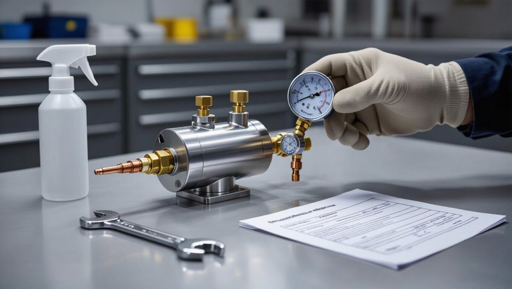
Manifold gas pressure is the measured pressure of fuel within a building’s distribution manifold and determines the flow delivered to appliances.
Incorrect manifold pressure can cause poor appliance performance, incomplete combustion, or dangerous leaks that compromise safety.
Typical units are inches of water column (in. w.c. or “wc”) or kilopascals, with normal residential pressures often around 3–7 in. w.c. and commercial systems varying by equipment requirements.
Definition of manifold pressure in gas systems
A gas manifold’s pressure is the force per unit area exerted by the gas within the manifold piping and fittings, typically measured in inches of water column (in. wc) or pounds per square inch (psi).
It indicates available supply to connected appliances, informs safe system limits, and guides procedures such as how to check gas manifold pressure using gauges and test fittings to verify correct, leak-free operation.
How manifold pressure affects appliance performance and safety
Pressure within the gas manifold directly determines how appliances burn, respond, and remain safe: too low a pressure can cause weak flames, incomplete combustion, and poor appliance performance, while too high a pressure can produce oversized flames, overheating, soot, or dangerous backflow.
Improper pressure increases carbon monoxide risk, damages components, shortens service life, and triggers safety shutoffs; correct pressure guarantees efficient, stable, and safe operation.
Common units and normal pressure ranges for residential and commercial systems
Units for measuring gas manifold pressure typically include inches of water column (in. w.c. or “wc”), pounds per square inch (psi), and kilopascals (kPa), and understanding their relationships is essential when comparing residential and commercial specifications. Typical ranges: residential ~3–14 in. w.c. (0.11–0.5 psi, 0.8–3.4 kPa); commercial often higher.
| System | Typical (in. w.c.) | Typical (psi/kPa) |
|---|---|---|
| Residential | 3–14 | 0.11–0.5 / 0.8–3.4 |
| Light commercial | 6–20 | 0.22–0.72 / 1.5–5.0 |
| Heavy commercial | 14–60 | 0.5–2.1 / 3.4–14.0 |
Who Should Check Manifold Pressure and When to Do It
Manifold pressure checks are generally performed by certified gas technicians, with homeowners advised to call a professional for complex systems, signs of leaks, or when regulatory compliance is required.
Competent DIYers may perform basic checks on simple installations if they understand the equipment, local laws, and safety procedures.
Routine inspections should follow manufacturer or regulatory schedules, while unexpected pressure drops, unusual odors, or system modifications warrant immediate testing.
Technician qualifications and when to call a professional
Although basic visual checks can be performed by many homeowners or building staff, measuring manifold pressure accurately and safely typically requires a trained HVAC/R or gas-service technician.
These professionals possess the appropriate certifications, experience with gas systems, and calibrated gauges to diagnose issues, interpret readings against appliance specifications, and take corrective action without creating hazards.
Call a professional for persistent leaks, unexplained pressure swings, appliance malfunctions, or anytime safety is uncertain.
Suitability for competent DIYers and legal/regulatory considerations
After noting when a professional is warranted, it’s helpful to outline which competent DIYers may safely perform manifold pressure checks and the legal limits on such work.
Competent DIYers with relevant training, proper tools, and understanding of local gas codes may perform basic pressure verification on accessible fittings.
Regulatory limits vary; permits, appliance certifications, or licensed contractor requirements must be checked before proceeding.
Routine schedules and situations that require immediate checks
Who should perform manifold pressure checks, and how often depends on the installation type and risk profile of the system.
Trained technicians handle commercial, industrial, and high-risk residential systems on scheduled monthly, quarterly, or annual intervals.
Homeowners or competent DIYers may inspect low-risk domestic systems annually.
Immediate checks are required after odor reports, pressure fluctuations, appliance changes, leak repairs, or safety device activations.
Tools and Equipment Needed for Safe Manifold Pressure Measurement
A clear inventory of instruments and protective gear is essential before measuring manifold pressure.
The discussion compares manometers, digital gauges, and pressure transducers, and reviews necessary PPE and leak-detection tools.
It also covers required fittings, hoses, adapters, and the importance of calibration checks.
Essential instruments: manometer vs digital gauge vs pressure transducer
Choosing the right instrument for measuring manifold pressure hinges on accuracy requirements, operating range, and the environment in which the measurement will be taken.
A U-tube or inclined manometer offers simple, reliable readings for low pressures.
Digital gauges provide faster readings, data logging, and higher precision.
Pressure transducers suit continuous monitoring and integration with control systems but require calibration and electrical power.
Personal protective equipment and leak-detection tools
Gloves, eye protection, and a flame-resistant jacket form the baseline personal protective equipment (PPE) for anyone working on gas manifolds, supplemented by respiratory protection when ventilation is inadequate.
Additionally, technicians should use hearing protection in noisy environments and insulated footwear.
Preferred leak-detection tools include calibrated electronic gas detectors, soap solution, and combustible gas sniffers; all tools must be intrinsically safe for the gas type and environment.
Required fittings, hoses, adapters, and calibration checks
Several specific fittings, hoses, and adapters are essential to confirm safe, accurate manifold pressure measurement: high-pressure-rated hoses with compatible end fittings, pressure-rated adapters matched to cylinder and regulator threads, and quick-connects or shutoff valves that are rated for the gas type.
Calibration and checks verify instrumentation accuracy and leak-free connections.
- Inspect hose and fitting ratings
- Use thread-matched adapters
- Verify valve compatibility
- Perform calibration and leak tests
Safety Precautions Before Starting a Pressure Check
Before beginning a manifold pressure check, the technician isolates the gas supply and applies lockout/tagout to prevent unexpected flow.
The work area is ventilated, ignition sources are controlled, and gas detectors are used to verify no leaks exist.
Emergency procedures are reviewed and first-aid equipment is made readily available.
Isolating gas supply and lockout/tagout procedures
Isolating the gas supply and implementing lockout/tagout (LOTO) are essential steps to guarantee no fuel reaches the manifold during a pressure check.
The technician should close upstream valves, bleed residual pressure, apply LOTO devices, and attach clear tags stating work details.
Verify isolation with pressure gauges or a test meter.
Only authorized personnel remove locks after completing and documenting the procedure.
Ventilation and ignition source control
When conducting a manifold pressure check, proper ventilation and strict control of ignition sources are critical to prevent accumulation of flammable gases and eliminate potential ignition pathways.
The work area should be assessed for airflow, supplemented with forced ventilation or exhaust as needed. All ignition risks—including pilot lights, electrical equipment, and static-generating tools—must be secured or de-energized before any fittings are opened.
Technicians should ventilate confined spaces, isolate potential sparks, and use intrinsically safe lighting and tools until testing is complete.
Verifying absence of leaks and using gas detectors
Following ventilation and ignition control measures, attention shifts to verifying the system is gas-tight and employing gas detectors to confirm no leaks are present.
Inspect fittings, valves and seals visually, then use a calibrated combustible gas detector or electronic sniffing device to sweep joints and access points.
Isolate suspected leaks, tighten or replace components, and re-scan until readings return to background levels.
Emergency procedures and first-aid readiness
Prepare for emergencies and secure first-aid readiness before any pressure check by establishing clear response procedures, assigning roles, and confirming available equipment.
Personnel must know evacuation routes, emergency shutdown, and communication protocols.
Guarantee a stocked first-aid kit, trained responder, and AED access.
Review incident reporting and local emergency contacts.
- Evacuation and shutdown
- Communication plan
- First-aid supplies
- Trained responder
Step-by-Step Procedure to Measure Gas Manifold Pressure
The technician begins by preparing the system, shutting off appliances and depressurizing lines before attaching a pressure gauge to the manifold test port.
Static (no-load) pressures are recorded after restarting the appliance, followed by operating (under-load) readings to observe any fluctuations.
All measurements are logged accurately for safety verification and compliance.
Preparing the system: turning off appliances and depressurizing lines
Before measuring manifold pressure, guarantee all downstream gas appliances are switched off at their controls and pilot lights are extinguished so the manifold and distribution lines can be safely depressurized.
Confirm isolation at appliance valves, shut the main supply if required, and wait for pressure to equalize.
Vent residual gas per local code, verify zero pressure with a meter, and wear appropriate PPE throughout.
Connecting the gauge safely to the manifold test port
Once the system is confirmed depressurized and isolated, a calibrated manifold gauge is connected to the test port using the correct adapter and fittings.
The technician inspects threads and seals, hand-tightens then secures with a wrench to avoid over-torque.
Flexible hose routing prevents strain.
All connections are checked with a leak detector or soapy solution before proceeding to procedures that introduce gas or start appliances.
Starting the appliance(s) and taking static (no-load) pressure readings
With the gauge verified leak-free and securely attached, power to the appliance(s) is applied following manufacturer start-up procedures so the gas valve opens without load on the regulator.
The technician observes gauge stabilization, records the static manifold pressure, notes ambient conditions and meter zero, then shuts the appliance pilot or burner per instructions.
Secure fittings and log readings for comparison.
Taking operating (under-load) pressure readings and interpreting fluctuations
When the appliance is brought under normal operating load, the technician connects the gauge to the manifold and observes pressure behavior while the equipment cycles through typical demand conditions.
Readings are taken after each cycle stabilizes long enough to capture a representative operating pressure. The technician notes peak, steady-state, and trough values, identifies transient spikes or drops, and evaluates whether fluctuations exceed manufacturer tolerances or indicate flow restriction, regulator hunting, or supply issues.
Recording and logging measurements for compliance
Begin by establishing a clear logging protocol that defines required parameters, sampling intervals, acceptable tolerances, and the format for entries (digital or paper).
Ensure every recorded manifold pressure measurement includes date, time, equipment ID, operating condition, measured value(s), and the technician’s initials.
Logs must be timestamped, tamper-evident, stored per retention policy, and reviewed regularly.
Nonconformances are documented and corrective actions recorded.
Interpreting Readings and What They Mean
The technician compares measured manifold pressures to the acceptable ranges for common appliances—cooktops, furnaces, and water heaters—to determine normal operation.
Deviations above or below those ranges are linked to specific symptoms and causes, such as regulator faults, supply issues, or appliance adjustments.
The distinction between an adjustment at the appliance and a required system repair is made by correlating the reading with observed behavior and upstream versus appliance-specific indicators.
Acceptable pressure ranges for common appliances (cooktops, furnaces, water heaters)
Different appliances require specific manifold pressures to operate safely and efficiently: typical residential natural gas cooktops and ovens usually need around 3.5–4.5 inches of water column (in. w.c.), most furnaces are calibrated for 3.5–7.0 in. w.c. depending on design and whether measurement is at the regulator or inlet, and standard water heaters typically expect 3.5–10.0 in. w.c.
| Appliance | Typical Range (in. w.c.) | Notes |
|---|---|---|
| Cooktop/Oven | 3.5–4.5 | Residential |
| Furnace | 3.5–7.0 | Varies by model |
| Water Heater | 3.5–10.0 | Tank or tankless |
Symptoms and causes of high manifold pressure
High manifold pressure in a gas system often manifests through distinct performance and safety symptoms that point to underlying faults; recognizing these signs helps isolate causes quickly.
Symptoms include yellow or lifting flames, soot buildup, pilot instability, gas odor, and overfiring.
Common causes are regulator failure, blocked downstream vents, incorrect regulator setting, excessive inlet pressure, or cross-connected supply lines requiring immediate correction.
Symptoms and causes of low manifold pressure
Diagnose low manifold pressure by correlating specific symptoms—weak or uneven flames, pilot outage, delayed ignition, burner click or pop, and gas appliances failing to reach operating temperature—with measured readings that fall below manufacturer or system specifications.
Common causes include upstream supply restrictions, undersized piping, partially closed valves, clogged regulators or filters, excessive demand from simultaneous appliances, or pressure drop from damaged fittings and gas leaks.
When a deviation indicates appliance adjustment versus system repair
Interpreting manifold pressure readings requires distinguishing whether the cause lies in an individual appliance’s adjustment or in the broader gas delivery system.
Technicians assess baseline pressure, compare appliance-specific tolerances, and inspect regulators, valves, and burners.
If one appliance shows deviation while supply and neighboring units remain stable, adjust or service that appliance.
Widespread deviations indicate regulator, supply line, or meter faults requiring system repair.
Common Problems Found During Pressure Checks and How to Respond
Common problems encountered during manifold pressure checks include leaks or loose fittings, regulator failures or blockages, and unstable or fluctuating readings.
The inspector should systematically check connections for leaks, verify regulator operation and filter/line obstructions, and monitor trends to isolate intermittent instability.
Each issue requires specific corrective actions or escalation to qualified technicians when repairs exceed routine maintenance.
Detecting and addressing leaks and loose fittings
Inspecting for leaks and loose fittings is a critical step when manifold pressure readings deviate from expected values.
Even small leaks or improperly tightened connections can cause significant pressure drops or fluctuations.
Technicians should perform a visual check, apply soapy solution to joints, listen for hissing, tighten fittings to specified torque, and replace damaged seals or components before retesting to confirm stable pressure.
Diagnosing regulator failures and blockage issues
Begin by isolating the regulator and visually inspecting it for signs of damage, corrosion, or improper installation that could impede operation.
Check inlet and outlet screens for debris, confirm vent paths are clear, and verify spring or diaphragm integrity.
Note unusual noise, persistent low pressure, or inability to hold setpoint.
Replace or service suspect regulators and remove blockages before retesting.
Steps for troubleshooting pressure instability or fluctuations
When pressure readings fluctuate or drift during checks, systematic isolation and verification of each component in the supply chain help pinpoint the cause.
Start by confirming steady inlet supply, then move downstream to regulators, gauges, relief valves, and piping for mechanical faults, leaks, blockages, or thermal effects that can induce instability.
- Verify inlet pressure stability.
- Inspect regulator function and vents.
- Check gauges and test instruments.
- Pressure-test piping, joints, valves for leaks or restrictions.
Adjusting Regulators and Making Safe Corrections
When pressure readings fall outside specified ranges, the technician assesses whether appliance pressure regulators require adjustment and follows manufacturer procedures for safe setting changes.
Faulty regulators or damaged components are removed and replaced using isolation and leak-testing steps to prevent gas hazards.
All corrections are confirmed by repeat manifold and appliance pressure measurements before returning the system to service.
When and how to adjust appliance pressure regulators
Adjusting appliance pressure regulators requires understanding safe operating limits, proper tools, and a step-by-step method to verify and correct settings without creating hazards.
Technicians confirm manufacturer pressure specs, isolate supply, attach calibrated gauge, and make small incremental adjustments while monitoring downstream pressure and appliance performance.
After adjustments, check for leaks, restore system, and document settings.
Never improvise or exceed rated limits.
Replacing faulty regulators and components safely
Begin by de-energizing and isolating the gas supply before any component removal or replacement, ensuring all pilot lights are extinguished and utilities are secured.
The technician uses rated tools, replaces regulators with manufacturer-specified parts, tightens fittings to torque specs, installs new seals, and applies leak detection.
Electrical connections are restored only after pressure-rated components pass visual inspection and venting is verified.
Verifying adjustments with follow-up measurements
After replacement, the technician confirms regulator settings by recording inlet and outlet pressures under normal and peak-load conditions, comparing readings to manufacturer specifications and system design values.
Follow-up measurements verify stability, droop, and response to load changes. Any deviation prompts incremental adjustments, retesting after each change.
Final documentation includes measured values, adjustment actions, timestamps, and signatures for accountability and future reference.
Documentation, Compliance, and Reporting After Testing
After testing, the technician records measured pressures, ambient and operating conditions, any corrective actions taken, and completes required regulatory forms and equipment stickers.
Copies of reports and handover notes are provided to the customer or building manager and retained per the applicable retention policy.
Recommended intervals for rechecks are noted on the report to guarantee ongoing compliance and safety.
What to record: readings, conditions, corrective actions
Record clear, concise entries for each manifold pressure test to guarantee traceability and compliance.
Include date, time, tester identity, instrument ID and calibration status, inlet and outlet pressures (with units), ambient conditions, observed fluctuations, and duration of readings.
Log corrective actions taken, parts replaced, torque or adjustment values, verification readings post-correction, and any safety incidents.
Store records securely for audit.
Regulatory forms, stickers, and handover to customers or building managers
Once entries are complete, documentation must be formalized for regulatory compliance and customer handover.
Technicians complete mandated forms, attach inspection stickers at the manifold if required, and prepare a concise handover sheet summarizing readings, adjustments, and safety notes.
Copies go to regulatory bodies and the customer or building manager; signatures confirm receipt.
Retain originals per applicable regulations.
Retention policies and recommended intervals for rechecks
When maintaining compliance, organizations should define clear retention periods for test records and a schedule for rechecks that reflect regulatory requirements, risk level, and equipment criticality.
Retain records long enough for audits, incident investigations, and warranty claims—commonly three to seven years or per statute.
Recheck intervals: monthly for critical systems, quarterly for moderate risk, annual for low-risk, or as specified by manufacturer and local code.
Best Practices, Tips, and Common Mistakes to Avoid
The section outlines preventive maintenance practices to help keep manifold pressure stable and predictable.
It also offers quick, practical tips for obtaining accurate readings and preventing contamination of gauges and lines.
Common mistakes and hazardous shortcuts are identified with clear corrections to reduce risk and guarantee reliable measurements.
Preventive maintenance tips to keep manifold pressure stable
Because manifold pressure reflects the combined condition of regulators, valves, and piping, routine preventive maintenance is essential to keep readings stable and systems safe.
Scheduled inspections, leak testing, filter replacement, and regulator calibration prevent drift. Lubricate moving parts per manufacturer guidance, verify venting and relief devices, document changes, and train personnel.
Promptly address corrosion, wear, and improper fittings to avoid pressure anomalies and failures.
Quick tips for accurate measurements and avoiding contamination
Several simple habits greatly improve manifold pressure measurements and reduce contamination risk.
Use clean, calibrated gauges and dry, oil-free tubing.
Purge lines before connecting sensors and collect samples upstream of potential contaminants.
Stabilize system temperature and pressure before reading.
Wear gloves and avoid introducing lubricants.
Record conditions and repeat readings to confirm consistency, noting any discrepancies for follow-up maintenance.
Common mistakes and how to avoid dangerous shortcuts
Good measurement habits reduce errors, but common mistakes and risky shortcuts can still undermine safety and data integrity.
Technicians should avoid complacency, improper isolation, and ad-hoc repairs. Follow procedures, use calibrated gauges, and verify zero before readings.
- Skip isolation valves — always isolate and vent.
- Use uncalibrated tools — calibrate regularly.
- Ignore leaks — test and repair first.
- Bypass safety devices — never bypass.
Example Scenarios and Stepwise Case Walkthroughs
The section presents concrete case walkthroughs for checking gas manifold pressure across common situations.
It covers a full residential gas range procedure with sample readings, a commercial boiler check with extra considerations and a checklist, and guidance distinguishing minor DIY fixes from issues requiring a licensed technician.
Each scenario is laid out stepwise to show expected outcomes and escalation points.
Residential gas range pressure check: full procedure and sample readings
Begin with an overview of the procedure and expected outcomes, outlining step-by-step checks, necessary tools, and typical pressure ranges for common residential gas ranges.
The technician isolates supply, connects manometer to test port, lights burners, notes static and operating pressures.
Typical readings: 3.5–7″ WC for natural gas, 8–11″ WC for propane.
Record deviations, adjust regulator, retest, and document results.
Commercial boiler manifold check: additional considerations and checklist
While commercial boiler manifold checks follow the same basic steps as residential range checks, they require additional attention to system complexity, higher flow rates, and safety controls.
The technician must consequently plan for multiple test points, staged firing, and coordination with building management.
Include isolation and lockout procedures, calibrated manometers, verification of safety interlocks, record baseline and under-load pressures, inspect venting and regulators, and document corrective actions.
DIY minor issue resolved vs. when to escalate to a licensed technician
After outlining the extra checks and safety steps for commercial manifolds, focus shifts to practical decisions a technician or competent homeowner must make when encountering minor gas issues: which problems can be safely resolved on-site and which require a licensed gas technician.
Provide concise scenarios:
- Loose fittings
- Clogged pilot
- Weak regulator
These can be addressed DIY with shutoff and leak-test.
Escalate for persistent leaks, pressure anomalies, odor, or complex regulators.
References, Standards, and Further Reading
The section lists applicable safety codes, manufacturer manuals, and industry standards that govern gas manifold pressure checks.
It also points to calibration resources and certified testing equipment suppliers for maintaining measurement accuracy.
Readers are directed to official documents and accredited vendors for authoritative guidance and procurement.
Relevant safety codes, manufacturer manuals, and standards
Because gas manifold pressure affects system safety and performance, technicians and engineers should consult applicable safety codes, manufacturer manuals, and industry standards before performing checks.
Key references include:
- National and local gas safety codes (e.g., NFPA, local regulations).
- Equipment manufacturer installation and maintenance manuals.
- Calibration and test procedure standards (traceable methods).
- Industry best-practice guidelines and accredited training materials.
Links to calibration resources and approved testing equipment suppliers
Consulting codes and manuals naturally leads to verified calibration sources and vetted equipment vendors that support compliant manifold-pressure measurements.
Trusted links include national standards bodies, accredited calibration labs, and manufacturer-authorized suppliers.
Recommended resources:
- NIST and equivalent standards organizations
- ISO/IEC 17025 accredited calibration labs
- Manufacturer-approved test gauges and transducers
- Certified safety equipment distributors and documentation portals
Conclusion
A concise, professional conclusion reinforces key points and offers a brief example. Proper manifold pressure checks protect equipment and people; only trained technicians or competent DIYers with the right tools should perform them, following safety steps, documented procedures, and applicable standards. For example, a bakery technician found a small regulator leak during routine checks, corrected it, and prevented a potential carbon monoxide incident—demonstrating how routine testing and clear documentation avert hazards and guarantee compliance.