How to Calibrate a Flow Meter: Step-by-Step Guide for Accurate Measurements
To calibrate a flow meter accurately, follow these steps: First, ensure safety isolation and inspect the device while matching process conditions to calibration requirements. Use a traceable reference standard, such as a prover or gravimetric system. Begin with zero checks, apply stepped flows, adjust the span, and document multiple runs for uncertainty analysis. Address specific issues like fouling or alignment as needed. Remember to adhere to scheduled maintenance and calibration intervals for optimal performance.
How to Calibrate a Flow Meter: Quick Overview and Objective
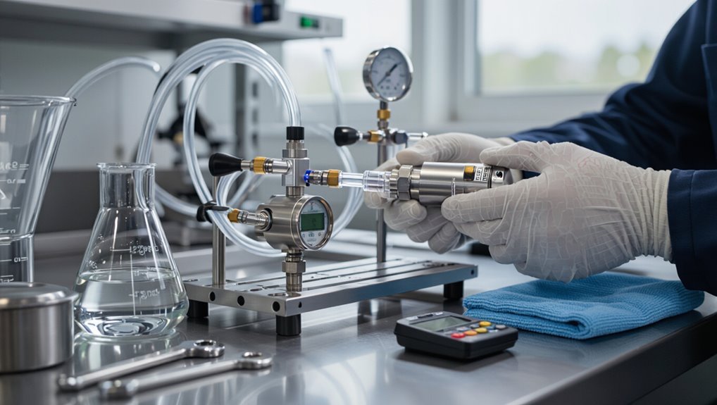
Calibration establishes the accuracy and traceability of a flow meter, ensuring measurements meet process, safety, and billing requirements.
It typically occurs on a scheduled basis—such as annually or per manufacturer recommendation—and also after repairs, process changes, or suspect readings.
Clear calibration objectives and trigger criteria help prioritize actions and maintain measurement confidence.
What calibration achieves and why it matters
Ensuring a flow meter reports accurate flow rates aligns instrument readings with a known standard, reducing measurement error and supporting reliable process control, billing, safety, and regulatory compliance.
Calibration verifies and corrects systematic deviations, quantifies uncertainty, and documents performance. Understanding how to calibrate a flow meter enables informed decisions on instrument suitability, traceability, and confidence in data used for operations, contracts, and audits.
When to calibrate a flow meter (frequency and triggers)
When should a flow meter be calibrated to maintain acceptable accuracy and compliance?
Calibration frequency depends on device type, process criticality, regulatory requirements, and historical drift. Routine intervals often range from monthly to annually; critical systems demand more frequent checks.
Triggers include notable measurement drift, after repairs or replacements, process changes, installation, or suspected contamination.
Records guide interval adjustments.
Types of Flow Meters and How Calibration Differs
Flow meter technologies—mechanical and positive displacement, turbine and paddlewheel, ultrasonic and electromagnetic, plus Coriolis and thermal mass—each rely on different sensing principles that affect calibration approach and frequency.
Calibration methods vary between on-site procedures, which prioritize convenience and minimal process disruption, and laboratory calibrations, which offer higher accuracy with controlled reference standards.
Understanding these distinctions guides selection of calibration equipment, acceptance criteria, and interval planning.
Mechanical and positive displacement meters
Different mechanisms govern mechanical and positive displacement (PD) meters, so their calibration requirements and error sources diverge.
Mechanical meters rely on moving parts like gears or pistons; wear, leakage, and friction affect accuracy. Calibration focuses on volumetric verification, wear inspection, and leak checks.
PD meters demand low flow resolution testing and repeatability assessment, with corrections applied to displacement per revolution.
Turbine and paddlewheel meters
Turbine and paddlewheel meters measure velocity-based flow by converting fluid motion into rotational or oscillatory signals.
Calibration emphasizes frequency response, signal conditioning, and hydraulic effects rather than solely volumetric checks.
Calibration verifies linearity across flow range, assesses mechanical friction and bearing wear, characterizes start/stop thresholds, corrects for fluid viscosity and density, and validates electronics and pulse scaling against a reference flow standard.
Ultrasonic and electromagnetic meters
Ultrasonic and electromagnetic meters measure flow using fundamentally different physical principles—sound-wave transit times or Doppler shifts in the case of ultrasonic devices, and Faraday’s law of induction for electromagnetic meters.
Calibration differs: ultrasonic requires careful transducer alignment, path averaging, and signal-to-noise checks; electromagnetic needs electrode condition, zeroing, conductivity verification, and stable reference flow.
Temperature and mounting affect both.
Coriolis meters and thermal mass meters
Compare Coriolis and thermal mass meters by their sensing physics and calibration needs:
Coriolis meters directly measure mass flow and density via vibrating flow tubes, requiring verification of tube vibration characteristics, phase shift, and zero stability.
Thermal mass meters infer mass flow from heat transfer, demanding checks of heater response, sensor placement, and fluid-specific calibration constants.
Calibration routines validate linearity, repeatability, and temperature compensation.
Differences in on-site vs. laboratory calibration
When calibration is performed on-site versus in a laboratory, differences in environmental control, reference standards, and test procedures produce distinct trade-offs in accuracy, repeatability, and practicality.
On-site calibration prioritizes minimal downtime and real-world conditions but accepts higher uncertainty.
Laboratory calibration delivers controlled conditions and traceable standards for superior precision yet requires removal, transport, and potential process disruption.
Applicability depends on tolerance and logistics.
Required Tools, Equipment, and Safety Precautions
A concise checklist of standard calibration tools and auxiliary equipment is presented to guarantee consistent procedures.
The discussion emphasizes reference standards, their required traceability to national or international norms, and documentation practices.
Required safety measures, including isolation procedures and lockout/tagout steps, are outlined to protect personnel and equipment during calibration.
Standard calibration equipment checklist
Several essential items comprise the standard calibration equipment checklist for flow meter work. Instruments must be reliable, compatible, and safe.
Core items include measurement standards, connection hardware, and safety gear.
- Calibrated reference flow standard and pressure/temperature sensors
- Assorted fittings, hoses, valves, and sealing materials
- PPE, leak detection tools, and isolation equipment
Reference standards and traceability requirements
Because accurate flow measurements depend on known standards, reference equipment must be traceable to national or international calibration laboratories and accompanied by valid certificates and uncertainty statements.
Traceability chains, calibration intervals, and environmental conditions must be documented.
Reference standards should exceed device accuracy, include uncertainty budgets, and be stored, handled, and maintained per manufacturer and laboratory protocols to preserve validity and comparability.
Safety measures and isolation procedures before calibration
Before any calibration work begins, technicians must isolate the flow meter from process lines, depressurize and drain associated piping, and lock out/tag out energy sources to prevent accidental flow, pressure, or electrical hazards.
Personnel should verify isolation with permits, pressure gauges, and continuity checks. Appropriate PPE, spill containment, ventilation, and grounding are required.
Emergency response plans and communication protocols must be confirmed.
Preparatory Steps Before Calibration
Before calibration, the meter and its associated piping should be inspected for damage, leaks, and proper installation.
Process conditions such as pressure, temperature, and fluid properties must be verified and recorded to confirm they match calibration requirements.
Baseline meter readings and maintenance history should be documented to provide a reference for post-calibration comparison.
Inspecting the meter and associated piping
Begin by visually and mechanically examining the meter and its adjoining piping to identify wear, leaks, misalignment, or obstruction that could skew calibration results.
Check seals, fittings, and mounting hardware for corrosion or looseness.
Inspect internal flow straighteners, strainers, and access ports for debris.
Confirm valve positions and bypass lines are correct and tag or document any findings requiring repair before proceeding.
Verifying process conditions (pressure, temperature, fluid properties)
Verify that the process conditions—system pressure, fluid temperature, and relevant fluid properties—match the specifications used for the meter’s calibration procedure or reference standards.
Measure and record pressure and temperature at appropriate locations, confirm fluid density and viscosity against calibration assumptions, and adjust or note deviations.
Guarantee steady-state conditions and no phase change, contamination, or entrained gases before beginning calibration activities.
Documenting baseline meter readings and history
A clear baseline record of the meter’s current readings and service history provides the reference needed to detect drift and validate calibration results.
Technicians should log serial number, model, firmware, installation date, recent repairs, last calibration data, ambient conditions, and multiple steady-state flow and zero readings.
Time-stamped photographs and signed entries guarantee traceability and support trend analysis and corrective actions.
Step-by-Step Calibration Procedure (General Method)
The technician establishes a reference flow using a calibrated standard and verifies the meter’s zero point, making any necessary zero adjustments.
Next, span is adjusted and linearity is checked at multiple points across the flow range, with several runs performed at each point for repeatability.
All measurements are recorded, averaged, and used to calculate correction factors for the meter.
Establishing reference flow using a calibrated standard
Begin by selecting and preparing a calibrated standard—such as a primary or secondary flow reference—whose uncertainty and operating range encompass the meter under test.
Install the standard inline, confirm fluid compatibility, stable supply pressure, and temperature control.
Generate setpoints across the meter’s range, allow stabilization at each point, record standard and meter readings, and document environmental conditions and timestamps for traceable comparison.
Zero-point check and adjustment
Before any flow is applied, perform a zero-point check to verify the meter reads nil under true zero conditions and determine if adjustment is required.
Isolate the meter, vent trapped fluid, and confirm stable environmental conditions.
Record the displayed value and compare to acceptable zero tolerance.
If out of tolerance, follow manufacturer procedures to adjust the zero, then repeat verification until within specification.
Span adjustment and linearity checks across flow range
Proceed to span adjustment and linearity checks by applying calibrated, known flow points across the meter’s operating range and recording the instrument’s output at each point.
Adjust span control to align one reference point, then verify others. Document deviations, calculate error percentages, and determine linearity by plotting output versus reference.
If nonlinearity exceeds tolerance, investigate sensor, electronics, or flow conditioning before finalizing calibration.
Performing multiple run comparisons and averaging results
After span and linearity adjustments are verified, multiple run comparisons provide statistical confidence in the calibration by repeating measurements at each reference flow and averaging the results.
The technician should perform a predetermined number of runs (typically three to five), maintain consistent conditions, note transient behavior, discard obvious outliers only with justification, and compute mean values to reduce random error before proceeding.
Recording calibration data and calculating correction factors
Record measurement results systematically, ensuring each reference flow, corresponding meter reading, ambient conditions, and run identifier are logged on a standardized form or electronic record.
Data are validated, outliers noted, and averages computed per flow point. Correction factors equal reference divided by meter average; apply temperature and pressure corrections as needed.
- Verify units and timestamps
- Document uncertainty sources
- Archive raw and processed data
Specific Calibration Procedures by Meter Type
The section outlines calibration steps tailored to each meter type, starting with common procedures and pitfalls for turbine and paddlewheel instruments.
It then presents single-path and multipath methods for ultrasonic meters, field verification steps for electromagnetic devices, and mass-plus-density checks for Coriolis systems.
Finally, it covers reference gas techniques used in thermal mass meter calibration.
Calibrating turbine and paddlewheel meters: steps and common issues
Begin by isolating the turbine or paddlewheel meter from process flow and verifying mechanical integrity—check for free rotor movement, bearing wear, and sensor alignment—before introducing calibration fluids and reference standards.
Perform flow-rate sweeps across operational range, record pulse output versus reference, adjust linearization factors, and verify repeatability.
Common issues: rotor fouling, magnetic sensor drift, cavitation, and incorrect zero/span settings; address before returning to service.
Calibrating ultrasonic flow meters: single-path and multipath methods
Calibrate ultrasonic flow meters by systematically comparing their time-of-flight or Doppler measurements against a traceable reference across the targeted flow range, using procedures tailored to single-path and multipath configurations.
For single-path units, verify beam alignment, path length, and velocity profile corrections.
For multipath systems, validate each path, average consistency, and algorithmic weighting.
Document environmental conditions, uncertainty, and corrective factors.
Calibrating electromagnetic flow meters: field verification steps
Perform a field verification of an electromagnetic (mag) flow meter by systematically confirming sensor integrity, electrical grounding, and flow profile assumptions before comparing readings to a traceable reference.
Inspect liner condition, electrode continuity, and insulation resistance.
Verify straight-run requirements, confirm zero flow offset, and check conductivity of the fluid.
Use a calibrated clamp-on or insertion reference; document ambient conditions and corrective actions.
Calibrating Coriolis meters: mass flow and density checks
Coriolis meters require verification of both mass flow and fluid density because their sensing principle directly measures mass and inertial effects.
A concise field procedure checks sensor dynamics, zero stability, and calibration factors against a traceable mass or master meter while accounting for temperature and pressure influences.
Perform zeroing, bidirectional checks, span adjustments using known mass totals, and density validation versus a calibrated densitometer, documenting uncertainties.
Calibrating thermal mass meters: gas reference methods
When validating thermal mass flow meters for gases, technicians should use traceable gas standards and controlled flow rigs to establish meter response across the expected operating range.
This includes steady-state points and representative transient conditions to capture the device’s heat-transfer dynamics.
Calibration compares meter output to reference mass flow (or calibrated sonic/nozzle devices), adjusts compensation for gas composition and temperature, and documents uncertainty and drift.
Calibrating positive displacement meters: leak and volume checks
Following gas-method checks for thermal mass meters, attention shifts to positive displacement (PD) meters, where mechanical integrity and volumetric accuracy govern performance.
Inspect seals and drive mechanisms for wear, then perform leak tests under static and dynamic conditions.
Use calibrated provers or gravimetric methods to measure displaced volume across flow rates, compare to nominal displacement, and adjust or repair until deviations meet tolerance.
Verification, Accuracy Assessment, and Tolerance Criteria
Verification begins with calculating measurement uncertainty and error percentage to quantify a meter’s performance under test conditions.
Acceptable tolerance bands, which vary by industry and application, are then applied to determine conformance.
If errors exceed those bands or uncertainty cannot be reduced by adjustment, the meter should be flagged for repair or replacement per established criteria.
Calculating measurement uncertainty and error percentage
Begin by quantifying both systematic and random components of measurement error to determine a flow meter’s overall uncertainty and express its deviation as a percentage of the measured value. Combine Type A (statistical) and Type B (bias) uncertainties, calculate expanded uncertainty with a coverage factor, and report error percentage relative to reading.
| Component | Example |
|---|---|
| Type A | Std. dev. |
| Type B | Calibration bias |
| Expanded | k·u |
Acceptable tolerance bands for different industries
Having quantified uncertainty and expressed error as a percentage of the reading, the discussion turns to industry-specific tolerance bands that define acceptable performance for flow meters across verification, accuracy assessment, and tolerance criteria.
Typical bands vary: custody transfer requires ±0.1–0.5%, custody accounting ±0.5–1%, process control ±1–2%, and general monitoring ±2–5%.
Regulatory standards and application risk dictate final acceptance limits.
When to reject, repair, or replace a meter
Decide meter disposition based on measured deviation, trend, and operational risk: a single out-of-tolerance reading near the allowable limit may warrant monitoring, while persistent or increasing errors, evidence of mechanical damage, or failures under custody-transfer conditions require immediate removal from service.
Assess root cause, repairability, cost of downtime, recalibration outcome, and safety implications; repair when fault isolated and economical, replace when accuracy cannot be restored.
Common Calibration Challenges and How to Troubleshoot Them
Calibration practice must address flow profile disturbances and piping effects, air entrainment or vapor lock, fluid contamination, electrical noise and signal instability, and sources of repeatability loss or drift.
Each issue requires targeted diagnostics—such as flow straighteners and upstream piping checks, bubble detection and contamination analysis, shielding and grounding inspections, and trend testing with reference standards.
Clear identification of the root cause allows selection of the appropriate corrective action and verification procedure.
Flow profile disturbances and piping effects
Flow profile disturbances and piping effects can considerably skew flow meter readings by altering velocity distribution, introducing swirl, or creating asymmetric profiles at the meter inlet.
Engineers should assess upstream/downstream straight-run requirements, install flow conditioners or spacers, minimize bends and valves near the meter, and verify installation alignment.
Documenting piping geometry and performing bench or in-situ profile checks aids calibration accuracy and repeatability.
Air entrainment, vapor lock, and fluid contamination
Addressing air entrainment, vapor lock, and fluid contamination is essential because trapped gases and foreign particulates can produce large, non-linear errors or intermittent signal loss during calibration.
Inspect lines for bubbles, bleed and purge vents, stabilize temperature and pressure to prevent vapor formation, and filter or flush fluids before testing.
Document fluid condition, repeat tests after remediation, and use degassing or inline filtration when necessary.
Electrical noise and signal stability problems
After ensuring fluids are free of gas and particulates, attention must shift to the electrical environment that governs sensor output and signal transmission.
Ground loops, EMI from nearby equipment, poor shielding, loose connectors, and inadequate power regulation introduce spikes, drift, or lost pulses.
Diagnose with an oscilloscope, verify grounding and shield continuity, tighten connections, use twisted-pair cabling, and add filtering or isolation as needed.
Repeatability issues and drift causes
Identify and quantify repeatability problems by running multiple steady-state tests under identical conditions and comparing the spread of readings. Consistent scatter beyond the instrument’s specified tolerance indicates intrinsic repeatability limits, mechanical play, or unstable process conditions.
Investigate drift by logging baseline over time, inspecting sensors for fouling, thermal effects, aging electronics, or zero-point shifts.
Corrective actions include cleaning, tightening, recalibration, temperature compensation, or component replacement.
Maintaining Calibration Records and Compliance
Maintaining complete calibration records—certificates, traceability documentation, and logbooks—is essential for demonstrating measurement integrity and supporting audits.
Relevant regulatory and industry standards such as ISO and API should be referenced to define acceptance criteria and documentation formats.
A clear re-calibration schedule, supplemented by condition-based triggers (e.g., process upset, drift detection, or repair), guarantees ongoing compliance and accuracy.
Essential documentation: certificates, traceability, and logs
Accurate calibration relies as much on documentation as on measurement procedure: calibration certificates, traceability chains, and detailed logs together establish the validity and provenance of a flow meter’s stated performance.
Records must be complete, legible, and retained per policy. Key elements include:
- Certificate details: date, technician, reference standards, uncertainties
- Traceability chain: calibration hierarchy and lab accreditation
- Logs: maintenance, adjustments, environmental conditions
Regulatory and industry standards to reference (e.g., ISO, API)
Why consult specific standards? Referencing ISO 17025, ISO 5167, API MPMS, and relevant national regulations guarantees traceability, measurement uncertainty control, and procedural consistency.
Compliance guides calibration methods, acceptance criteria, and documentation formats. Organizations should adopt applicable standards for legal, safety, and quality auditing, noting industry-specific requirements (oil/gas, water, pharmaceuticals) and retaining evidence for inspections and accreditation.
Scheduling re-calibration and condition-based triggers
When establishing a re-calibration schedule, organizations should balance manufacturer recommendations, historical drift data, and process criticality to define intervals that guarantee measurement integrity without unnecessary downtime.
Re-calibration frequency is adjusted by performance trends, operational stress, and regulatory demands. Condition-based triggers—unexpected shifts, repairs, extreme operating conditions—prompt immediate checks.
Documentation of triggers, actions, and outcomes supports auditability and continuous improvement.
Tips to Improve Long-Term Measurement Accuracy
Proper installation practices—correct piping, grounding, and flow conditioning—minimize sources of error and reduce the need for frequent recalibration.
Regular routine inspections and preventive maintenance, such as cleaning strainers and checking seals, sustain sensor performance over time.
Continuous diagnostics and remote monitoring systems help detect gradual drift early, enabling targeted adjustments before accuracy degrades.
Installation best practices that reduce calibration frequency
Several straightforward installation choices can greatly extend the interval between required calibrations by minimizing sources of measurement drift.
Mount meters per manufacturer orientation, guarantee adequate straight-run inlet/outlet piping, and avoid turbulent fittings nearby.
Provide stable support to prevent vibration, maintain proper grounding and electrical isolation, and install filtration or strainers upstream.
Position sensors away from heat sources and avoid air pockets in liquid lines.
Routine checks and preventive maintenance tasks
Routine inspections and simple preventive maintenance tasks keep a flow meter operating within specifications and help detect drift before it affects process control.
Regularly verify zero and span, clean sensors and strainers, and confirm mechanical integrity. Document findings and schedule corrective actions.
- Check for buildup and blockages
- Tighten fittings and inspect seals
- Replace worn parts per manufacturer intervals
Using diagnostics and remote monitoring to detect drift
Leverage built-in diagnostics and remote monitoring to identify subtle drift before it degrades process control.
The system logs sensor outputs, alarms, and performance trends, enabling automated comparisons against baseline calibrations.
Remote alerts notify technicians of deviations, facilitating prioritized verification, targeted recalibration, or sensor replacement.
Historical analytics support root-cause analysis and optimize maintenance intervals, minimizing downtime and preserving long-term measurement accuracy.
Example Calibration Checklist and Template
A concise pre-calibration checklist guarantees all equipment, environmental conditions, and documentation are verified before measurements begin.
The calibration run template standardizes test steps and records essential data fields such as flow rates, reference standards, timestamps, and uncertainty estimates.
Together, these tools streamline procedures and support repeatable, auditable results.
Pre-calibration checklist items
Prepare a concise pre-calibration checklist that certifies all equipment, environmental conditions, documentation, and personnel are ready before flow meter verification begins.
Verify instrument cleanliness, seals, and fittings; confirm reference standards’ calibration status and traceability; confirm ambient temperature, pressure, and flow stability; guarantee trained staff and safety measures.
- Equipment integrity and calibration status
- Environmental condition verification
- Personnel readiness and paperwork
Calibration run template and data fields
Begin the calibration run by recording a concise template that captures each trial’s identifying information, setpoints, measured values, and pass/fail decisions. The template lists trial ID, target flow, observed flow, timestamp, uncertainty, and acceptance criteria. Use a consistent table for quick review and traceability.
| Trial ID | Setpoint (L/min) | Measured (L/min) |
|---|---|---|
| T1 | 10.00 | 9.98 |
| T2 | 50.00 | 50.12 |
| T3 | 100.00 | 99.85 |
When to Use Professional Calibration Services
Decisions to outsource flow meter calibration hinge on factors such as complexity of the instrument, required accuracy, regulatory requirements, and in-house capabilities.
Selection of a calibration provider should prioritize accreditation, traceability to standards, documented procedures, and references or demonstrated experience with similar meters.
Cost considerations and expected turnaround times must be weighed against downtime risk and the value of certified results.
Criteria for outsourcing calibration
When calibration needs exceed in-house expertise, tight tolerances, or regulatory scrutiny, organizations should consider professional services. External labs offer accredited procedures, traceable standards, and liability coverage that internal teams often cannot match.
Criteria for outsourcing include frequency and complexity of calibrations, required uncertainty and traceability, cost-benefit versus internal capability, downtime risk, and contractual or legal obligations mandating independent, accredited verification.
What to look for in a calibration service provider
Having determined that external expertise is appropriate, selecting the right calibration provider hinges on clear technical, quality, and commercial criteria.
The provider should demonstrate traceable standards, documented procedures, and responsive support.
Evaluate:
- Accreditation (ISO/IEC 17025) and traceability to national standards
- Proven experience with the specific flow meter type and range
- Transparent reporting, corrective actions, and data integrity
Cost factors and turnaround expectations
Cost considerations and turnaround expectations directly influence whether to pursue in-house calibration or engage a professional service.
Decision factors include number of meters, frequency, travel or shipping costs, required accreditation, and downtime impact.
Professionals often provide faster, traceable results with higher fees; in-house saves per-check costs but requires equipment, staff training, and validation.
Compare total cost of ownership and operational risk.
Closing Summary: Key Takeaways for Accurate Flow Meter Calibration
Although procedures vary by meter type and application, the essential principles remain consistent: establish and document reference standards, verify installation and flow profile, control test conditions, use appropriate calibration methods, and record uncertainties.
Consistent documentation, periodic verification, traceable standards, and training sustain accuracy.
Prioritize root-cause analysis for discrepancies, apply corrective actions, and maintain clear calibration schedules to guarantee reliable measurement and compliance.
Conclusion
Accurate flow meter calibration protects process integrity and reduces costly errors. Following proper preparation, using suitable reference standards, and documenting results guarantees repeatable performance across meter types. Routine checks and corrective adjustments keep measurements on the straight and narrow, while adherence to safety and traceability standards preserves data credibility. For complex systems or failing instruments, professional calibration services provide certified accuracy. Consistent application of these practices yields reliable flow measurements and confident operational decisions.