How to Install a Ball Valve on Copper Pipe: Step-by-Step Guide for DIY Plumbers
To install a ball valve on copper pipe, start by selecting the right type of valve—sweat, compression, push-fit, or threaded. First, shut off and drain the water line. Wear safety gear and prepare the copper pipe by cutting it square and deburring the edges.
For sweat valves, apply flux and solder the joint; for compression valves, assemble the ferrule and nut, then tighten them. With push-fit valves, mark the insertion depth and push the valve onto the pipe. For threaded connections, use sealant to ensure a tight fit. After installation, test for leaks, exercise the handle, and document your work. Detailed steps and troubleshooting tips are provided below.
Overview of Installing a Ball Valve on Copper Pipe
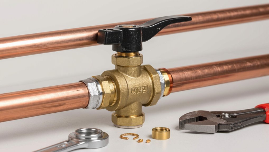
A ball valve is a quarter-turn shutoff device used to control flow and is chosen when a reliable, low-maintenance isolation point is needed on copper piping.
Suitable types for copper include sweat, compression, push-fit, and threaded ball valves, each matching different skill levels and connection preferences.
Required tools and materials vary by type—soldering kit and flux for sweat, wrenches and ferrules for compression, a clean pipe and push-fit valve for press-in, and pipe thread sealant and fittings for threaded installations.
What a ball valve is and when to use it
Ball valves are quarter-turn shutoff devices that use a hollow, rotating sphere to control flow; they provide reliable, near-100% shutoff and quick operation.
They suit isolation points, emergency stops, and sections requiring infrequent operation.
Durability and low pressure drop make them practical for potable and service lines.
Guidance on how to install ball valve on copper pipe focuses on secure connections and proper sizing.
Types of ball valves suitable for copper pipe (sweat, compression, push-fit, threaded)
Valves for copper pipe installations come in several connection styles—sweat, compression, push-fit, and threaded—each offering distinct trade-offs in permanence, tools required, and ease of service.
- Sweat: soldered joint, permanent, reliable for long runs.
- Compression: mechanical seal, serviceable without heat.
- Push-fit: quick, tool-free, ideal for repairs.
- Threaded: versatile, needs adapters for copper.
Tools and materials required for each valve type
Several specific tools and materials are required depending on whether the connection is sweat, compression, push-fit, or threaded.
Each valve type needs distinct prep and fittings: solder and flux for sweat; compression nut, ferrule, and wrenches for compression; clean pipe and push-fit valve for push-fit; thread sealant and matching male thread for threaded.
- Sweat: torch, flux, solder
- Compression: wrench, ferrule
- Push-fit: deburring tool, clean cloth
- Threaded: pipe dope, tape
Safety Precautions and Preparation
Before any work begins, the water supply should be shut off and the line relieved of pressure to prevent leaks or injury.
Appropriate personal protective equipment and a cleared, well-lit workspace minimize hazards during cutting and soldering.
Finally, local plumbing codes and permit requirements should be verified to confirm the installation complies with regulations.
Turning off water supply and relieving pressure
Locate and shut off the main water supply to the section of piping where the ball valve will be installed.
Then open the nearest faucet downstream to relieve residual pressure and drain any remaining water from the line.
Verify shutoff by checking multiple fixtures.
Close downstream faucets after drainage.
Consider isolating the specific branch valve if available to avoid shutting off the entire building supply.
Personal protective equipment and workspace setup
Adequate personal protective equipment and a well-organized workspace are essential to prevent injury and protect the plumbing during valve installation.
The installer should wear safety glasses, gloves, and hearing protection as needed.
Clear the area of obstructions, lay down absorbent cloths for water and debris, guarantee good lighting, and keep tools and fittings within reach to maintain efficiency and safety.
Checking local codes and permits
Why check local codes and permits? Local codes dictate approved materials, joint methods, pressure ratings and required inspections.
Permits guarantee compliance, avoid fines and preserve insurance coverage. The installer should contact the municipality or building department, verify permit needs, follow permit conditions, and schedule inspections if required.
Document approvals and retain records for future property transactions or warranty claims.
Measuring and Selecting the Right Valve
Accurate measurement of copper pipe outer diameter and wall thickness is essential to determine the nominal size and plumbing classification.
The chosen valve must match the pipe connection type—sweat, compression, or push-fit—and be compatible with the system layout.
Valve material and stamped pressure/temperature ratings should be selected to suit the fluid, operating conditions, and local code requirements.
How to measure copper pipe size and wall thickness
Measuring a copper pipe’s nominal size and wall thickness requires two simple tools: a caliper for outside diameter (OD) and a micrometer or pipe gauge for wall measurement.
Measure OD at several points to confirm roundness. Subtract twice the wall thickness from OD to calculate internal diameter if needed.
Compare OD and wall to standard nominal sizes (Type K, L, M) for correct valve selection.
Matching valve connection type to pipe and system
Select the correct valve connection by matching the valve type to the pipe material, diameter, wall thickness, and the system’s operating conditions.
Determine whether sweat, compression, threaded, or push-fit ends suit the copper tubing and available space.
Confirm compatibility with fitting standards (e.g., Type K/L/M OD/ID differences) and verify joint method aligns with installation skill level, tools, and maintenance access.
Choosing materials and pressure/temperature ratings
Evaluate valve materials and ratings against the copper piping system’s operating demands before purchase.
Select compatible metals—bronze, brass, or stainless steel—to prevent corrosion and galvanic reaction.
Confirm pressure (PSI/bar) and temperature limits exceed worst-case system conditions, including thermal shock.
Choose appropriate seals (PTFE, EPDM) for fluid type.
Verify certification standards (ASME, NSF) for potable or HVAC applications.
Step-by-Step Installation for Sweat (Soldered) Ball Valve
The following section outlines the step-by-step procedure for installing a sweat (soldered) ball valve on copper pipe.
It covers preparing the pipe (cutting, deburring, and cleaning), applying flux and seating the valve, and using correct soldering technique while noting common mistakes to avoid.
The sequence concludes with cooling, cleaning the joint, and performing an initial leak test.
Preparing the copper pipe (cutting, deburring, cleaning)
Prepare the copper pipe by cutting it square, removing burrs, and thoroughly cleaning the outside and inside surfaces to guarantee a reliable soldered joint.
Measure and mark the cut, use a proper tubing cutter for a clean edge, ream or deburr the inside to remove sharp edges, and abrade the outside with emery cloth.
Wipe with a clean rag and solvent until bright.
Applying flux and fitting the valve
With the pipe ends clean, flux is applied to both the outside of the tubing and the valve’s sweat socket to promote solder flow and prevent oxidation.
The valve is slid fully onto the tube until it seats firmly. Excess flux is wiped away.
Alignment is checked to guarantee the handle will operate freely and the assembly remains square before proceeding to heat and solder.
Proper soldering technique and common pitfalls
Begin heating evenly around the valve socket and pipe, directing the flame to the joint rather than the pipe body so solder is drawn into the seam by capillary action.
Maintain steady heat, apply solder when flux liquefies, and feed until a continuous fillet appears.
Common pitfalls: overheating the valve, insufficient flux, dirty surfaces, moving parts during soldering, and using excessive solder that clogs the bore.
Cooling, cleaning, and initial leak test
Allow the joint to cool naturally to ambient temperature before any handling to prevent fresh solder from cracking or shifting.
Once cool, remove flux residue with a damp rag or approved cleaner to prevent corrosion.
Inspect the bead for gaps or cold joints.
Perform an initial leak test by pressurizing the line slowly, checking connections and valve seats for drip or seepage, and tighten or rework as needed.
Step-by-Step Installation for Compression Ball Valve
For a compression ball valve, the installer first cuts the copper pipe squarely and removes burrs to guarantee a proper seal.
Next the nut, ferrule, and valve are assembled in the correct order and tightened to the manufacturer’s recommended torque before the joint is tested for leaks.
Reuse of ferrules is generally discouraged; replace them when deformed or after multiple fittings to maintain reliability.
Cutting and deburring the pipe for compression fitting
Cut the copper pipe squarely to the required length using a tube cutter or fine-tooth saw, then remove burrs and sharp edges from both the inside and outside of the cut end so the compression nut and ferrule seat properly and the valve seals reliably.
Deburr with a reamer or file, wipe away filings, and verify roundness and clean, smooth edges for a leak-free compression joint.
Assembling the nut, ferrule, and valve correctly
With the pipe end clean, round, and free of burrs, assembly of the compression components can begin.
The nut slides onto the pipe first, threads facing the valve. The ferrule follows, oriented per manufacturer markings—small end toward the valve.
Insert the pipe fully into the valve body, seat the ferrule, then slide the nut forward, engaging threads by hand until finger-tight and aligned.
Tightening torque and testing for leaks
Begin tightening the compression nut using a wrench until it reaches the manufacturer’s specified torque or a snug, firm resistance if no torque spec exists.
After tightening, pressurize the line slowly and inspect joints for visible drips.
Wipe connections and check for weeping over several minutes.
If leaks appear, tighten incrementally; if persistent, depressurize before disassembly and correct seating or alignment.
Reuse considerations and when to replace ferrules
Several factors determine whether a compression ferrule can be reused: visible deformation, deep scoring, or loss of its original cone shape indicate replacement, while a clean ferrule with only minor compression marks may sometimes be reused.
Reuse risks include leaks from imperfect seating and weakened metal. Replace ferrules if corrosion, cracks, or pronounced set exists.
When in doubt, install a new ferrule for reliable seals.
Step-by-Step Installation for Push-Fit (SharkBite-style) Ball Valve
The section outlines the push-fit ball valve installation process, starting with preparing and deburring the copper pipe to guarantee a straight, clean insertion.
It covers marking the correct insertion depth, seating the valve, and procedures for removing and re-seating a push-fit connection if needed.
Finally, it explains how to verify the seal and perform a pressure test to confirm a leak-free installation.
Preparing pipe and ensuring straight insertion
Prepare the copper pipe by cutting, deburring, and cleaning the end so the valve seats fully and seals reliably.
The installer guarantees the pipe end is square, free of burrs and debris, and wiped dry.
Pipes must be supported to prevent misalignment; the valve should be pushed straight on without angling.
Minor twisting is acceptable, but lateral force that distorts seating must be avoided.
Marking insertion depth and installing the valve
Measure and mark the pipe to the valve’s specified insertion depth using a ruler or depth gauge, then verify the mark aligns with the valve shoulder when pushed on.
Apply a light chamfer to the pipe end, remove debris, and guarantee the pipe is dry.
Push the valve straight onto the pipe until the shoulder meets the mark, then rotate slightly to confirm secure engagement.
How to remove and re-seat a push-fit valve
To remove and re-seat a push-fit ball valve, first relieve system pressure and isolate the section by shutting off upstream and downstream supply valves.
Depress the release collar with a proper tool, pull the pipe free, and inspect the O-ring and pipe end for burrs or debris.
Reinsert to the marked depth until it clicks, ensuring straight alignment and full engagement.
Verifying seal and pressure testing
With the valve re-seated and alignment confirmed, attention shifts to verifying the seal and conducting a pressure test to confirm leak-free operation.
The installer slowly restores water, observes the joint for drips, and feels for moisture.
After isolation, a pressure gauge or system pump raises pressure to specified levels; hold for several minutes.
Any drop or seepage requires re-seat or replacement before putting the system back into service.
Step-by-Step Installation for Threaded Ball Valve on Copper Pipe
The section explains how to shift from copper tubing to threaded ball valves using appropriate male or female adapters soldered or fitted to the copper.
It covers proper application of PTFE tape or pipe dope to threaded connections to guarantee a reliable seal.
Guidance on correct torque levels and systematic leak-checking of the threaded joints is provided to prevent overtightening and detect any failures.
Adapting copper to threaded connections (male/female adapters)
Begin by preparing the copper pipe and selecting the correct male or female adapter that matches the valve thread size and pipe OD.
Fit a compression or sweat adapter onto the cut, deburred pipe; secure per adapter type.
Confirm alignment, support the pipe, then thread the adapter into the ball valve.
Check for straightness and verify mechanical stability before proceeding to sealing.
Using thread sealant or PTFE tape properly
Prepare to seal the threaded joint by choosing the correct sealant and applying it methodically: for metal-to-metal pipe threads PTFE tape (white) or a pipe thread compound rated for potable water should be used, applied only to the male threads, wrapped clockwise (so it does not unravel when the valve is threaded on), covering 2–3 full turns without overlapping the first thread at the shoulder.
Pipe dope may be brushed on evenly instead of tape, avoiding excess that could contaminate the system.
After assembly, the joint should be tightened to the valve manufacturer’s torque spec and checked for leaks under pressure.
Torque guidance and leak-checking threaded joints
After the sealant is applied and the valve threaded hand-tight to the fitting, attention turns to achieving the correct torque and verifying a leak-free joint.
A wrench snugly advances the valve one to two additional turns; avoid overstressing copper.
Once torqued, pressurize the line and inspect all seams with soapy water or leak detector.
Retorque lightly if small bubbles appear; replace sealant if persistent.
Testing, Commissioning, and Final Checks
Following installation, the procedure moves to pressure testing protocols tailored to each valve type to confirm integrity under working conditions.
The installer then verifies valve operation and correct orientation, exercising the handle through full travel and confirming flow control.
Finally, common leak points—threads, solder joints, and compression seats—are inspected and remedied with tightening, re-soldering, or seal replacement as needed.
Pressure testing procedures for each valve type
Begin by isolating each installed valve and documenting its type, location, and orientation before pressurization to guarantee accurate, traceable testing. Pressure tests follow manufacturer limits: gradually raise to test pressure, hold, inspect for leaks, record results, and depressurize slowly. Different valve types require specific durations and media; safety precautions apply.
| Valve Type | Test Notes |
|---|---|
| Ball | Short hold, water |
| Gate | Longer hold |
| Check | Flow direction |
| Globe | Moderate hold |
Checking valve operation and orientation
Verify that each valve operates smoothly and is oriented correctly relative to flow direction and system schematics before final commissioning.
Confirm handle movement from fully open to fully closed without binding, and check ball alignment marks match piping flow arrows.
Cycle valves under low pressure to detect sticking.
Ascertain mounting brackets do not strain joints.
Document positions and note any anomalies for corrective action.
Addressing common leak locations and remedies
With valve operation confirmed and orientation documented, attention turns to common leak locations and their remedies during testing and commissioning.
Inspect solder joints, compression nuts, and valve stem seal for weeps.
Tighten fittings incrementally, reflow or re-solder poor joints, replace damaged compression rings or ferrules, and swap faulty valves.
Pressure-test to final spec and recheck after several hours under load.
Troubleshooting Common Problems
Common installation issues include leaks at soldered joints, compression ferrules, and push-fit connections that require systematic inspection and repair.
Stiff or hard-to-turn balls, corrosion or galvanic reactions between dissimilar metals, and misaligned or undersized fittings each have distinct causes and corrective actions.
The following steps outline diagnoses and practical fixes to restore proper valve function and guarantee long-term compatibility.
Leaks at soldered joints, compression ferrules, and push-fits
Leaks at soldered joints, compression ferrules, and push-fit fittings are among the most frequent causes of post-installation seepage and require different diagnostic steps.
Inspect for visible gaps, cold solder joints, loose nuts, crushed ferrules, or improperly seated push-fit O-rings.
Dry and pressurize sections, isolate the fault, then reflow solder, tighten or replace ferrules, or reseat/replace push-fit fittings as indicated.
Stiff or hard-to-turn valve ball and how to free it
A ball valve that feels stiff or difficult to turn indicates internal binding, corrosion, mineral buildup, or prolonged inactivity that restricts the ball’s rotation and compromises operation.
To free it, shut water, relieve pressure, and apply penetrating lubricant to the stem and handle pivot. Cycle gently back and forth.
If movement improves, flush the line and operate periodically; replace the valve if resistance persists.
Corrosion, galvanic issues, and material compatibility
If a previously stiff valve was freed only to reveal white powdery deposits or green staining, the problem may be corrosion or galvanic action between dissimilar metals.
The guide recommends inspecting metal types, checking for electrochemical corrosion where copper contacts brass or steel, ensuring dielectric unions or compatible fittings, and replacing compromised valves.
Regular inspection and proper material selection prevent leaks and accelerated degradation.
Fixes for misaligned or undersized fittings
Addressing misaligned or undersized fittings begins with identifying the specific dimensional or alignment mismatch causing stress or gaps at the joint.
Solutions include using appropriate adapters, sleeves, or couplings; re-cutting and re-deburring pipe ends; realigning supports and hangers; or replacing the fitting with the correct size.
Test for leaks after repair and evenly tighten connections to avoid renewed misalignment.
Maintenance and Long-Term Care
Routine inspections should be scheduled (e.g., every 6–12 months) to check for leaks, corrosion, handle stiffness, and seals that indicate wear.
Periodic lubrication of the stem, exercising the valve by fully opening and closing it on a set schedule, and winterizing exposed valves help extend service life.
Guidance on when to repair sealing parts versus replace the entire valve should be based on extent of corrosion, persistent leaks after service, and component availability.
Recommended inspection schedule and signs of wear
When should a ball valve and its surrounding copper piping be inspected to guarantee reliable operation and prevent leaks?
Routine inspections are advised quarterly for visible systems and annually for concealed runs.
Check for corrosion, green or white deposits, pinhole leaks, loose fittings, handle play, and water stains.
Note stiffness, unusual noises, or pressure fluctuations; document findings and schedule repairs promptly.
Lubrication, exercise (operating) frequency, and winterizing
Maintain ball valves on copper pipe with regular lubrication, periodic operation, and seasonal winterizing to guarantee smooth function and prevent freezing or seizure.
Apply a compatible, non-reactive lubricant to stems annually or per manufacturer instructions. Cycle valves quarterly to keep seals supple.
Before cold weather, drain lines, insulate exposed valves, and shutoff or winterize connected fixtures to reduce freeze risk and corrosion.
When to replace the valve versus repair
How long should a ball valve be expected to last before repair or replacement becomes necessary?
Service life varies with material and use; quality valves often last decades.
Repair is appropriate for minor leaks, stiff operation, or worn seats.
Replace when corrosion, persistent leakage after repair, damaged ball or stem, or frequent failures occur.
Prioritize safety, water quality, and long-term reliability when deciding.
Time, Cost, and When to Call a Professional
Typical DIY installation of a ball valve on copper pipe takes one to two hours and commonly costs between $15 and $75 for parts and basic tools.
Tasks involving soldering near existing fittings, limited access, corroded pipe, or complex shutoff requirements are signs to hire a licensed plumber.
Before hiring, ask about licensing and insurance, an estimated total cost and timeline, warranty on work, and whether permits will be required.
Estimated time and cost breakdown for DIY installations
A straightforward ball-valve installation on accessible copper pipe usually takes an experienced DIYer 30–90 minutes, while a novice should plan for 1–3 hours to allow for prep, cutting, deburring, and flux/solder or compression fitting steps. Expected costs vary by method and materials; labor is saved but factor in tools and spares.
| Item | Typical Cost | Time Impact |
|---|---|---|
| Ball valve | $8–$30 | Low |
| Solder kit | $10–$25 | Medium |
| Compression kit | $5–$20 | Low |
| Misc/parts | $2–$15 | Low |
| Tools (amortized) | $5–$30 | High |
Complexity indicators that warrant hiring a plumber
Moving from basic time-and-cost estimates to indicators for professional help, certain situations meaningfully increase complexity and risk, making a plumber the practical choice.
Examples include corroded or brittle copper, pipes in concealed walls or slabs, multiple fittings or branches, leaking after attempted repair, required permits or code compliance, limited access, and emergency shutoff failures.
These escalate time, cost, and liability.
Questions to ask a professional plumber before hiring
When should a homeowner call a plumber and what should they expect to pay? A homeowner should call for leaks, corrosion, failed solder joints, or unfamiliar installations.
Ask the plumber: licensing and insurance, hourly rate versus flat fee, estimated total cost, warranty on labor and parts, timeline for completion, disruption level, disposal of old components, and emergency availability.
Get a written estimate.
Helpful Tips and Best Practices for Reliable Installations
A concise set of best practices helps prevent common errors and guarantees the valve and pipe remain compatible over time.
Recommended checks include:
- Inspect for proper pipe sizing and wall thickness.
- Verify joint method and valve material compatibility.
- Confirm correct soldering or compression technique.
- Record installation details, date, and any parts used.
Following these steps reduces callbacks and simplifies future maintenance.
Avoiding the most common DIY mistakes
Avoid common pitfalls by preparing properly, using the right tools, and following proven steps to confirm a secure, leak-free ball valve installation on copper pipe.
Inspect fittings for damage, deburr and clean pipe ends, and ascertain correct soldering or compression technique.
Avoid overtightening, skip inadequate flux or solder, and test at recommended pressure.
Document work and recheck for hidden stresses.
Material compatibility checklist
Because incompatible materials can cause leaks, corrosion, or mechanical failure, a concise compatibility checklist is essential before installing a ball valve on copper pipe.
Verify valve body metallurgy (bronze, brass, or copper-compatible alloys), gasket and seat materials (EPDM, PTFE), solder/flux compatibility, and thread sealant suitability.
Confirm pressure-temperature ratings match system requirements and avoid dissimilar metal contact without dielectric unions.
How to document work for future maintenance
Documenting the installation guarantees future technicians can quickly assess condition, troubleshoot issues, and perform maintenance without guesswork.
Record valve type, size, orientation, solder or joint method, and date. Photograph before-and-after positions and label nearby shutoffs.
Note flow direction, pressure rating, and any adapters used.
Store records with schematic or location map and include tester results and warranty details for efficient future service.
Related Upgrades and Alternatives
The section outlines upgrade paths such as switching to isolation manifolds or multi-valve setups for zoned control and easier maintenance.
It also notes retrofit options to meet lead-free requirements or higher pressure ratings.
Finally, compatibility with smart valves and basic automation integration is addressed for remote monitoring and control.
Converting to isolation manifolds or multi-valve setups
Several homeowners choose to replace single inline ball valves with isolation manifolds or multi-valve assemblies to improve serviceability and zoning.
These systems centralize shutoffs, allowing isolation of individual branches for maintenance without disrupting entire systems.
Installation requires planning for space, pipe routing, and correct sizing; coupling methods mirror standard copper techniques.
Manifolds enhance control and reduce downtime, especially in multi-zone plumbing layouts.
Retrofit options for lead-free or high-pressure systems
Upgrading from standard manifolds or single inline valves often prompts consideration of material and pressure compatibility, particularly where potable-water lead limits or higher supply pressures apply.
Retrofit choices include certified lead-free brass, stainless steel, or bronze ball valves and pressure-rated fittings.
Use solderless compression, press-fit, or flared connections certified for target pressure.
Confirm system pressure, code compliance, and use compatible seals and rated adapters.
Smart valve and automation compatibility considerations
How will a ball valve integrate with home automation, and which communication protocols and power options matter most?
The guide notes protocol compatibility—Zigbee, Z-Wave, Wi‑Fi, Bluetooth—and controller requirements.
It advises checking actuator voltage (battery, 12/24V DC, mains) and fail-safe behavior.
Physical mounting, feedback sensors, and API or hub support determine suitability for timed schedules, remote shutoff, leak detection, and integration with existing smart systems.
Conclusion
The DIY plumber completes the copper pipe job with steady hands and a pocket watch ticking like a steam engine. After measuring, choosing the proper valve, and following either sweat or compression steps, the installation proves reliable. Routine checks, occasional lubrication, and attention to leaks keep the system sound. If complexity or uncertainty arises, a professional should be summoned. Proper care guarantees years of trouble-free service and peace of mind for the household.