How to Fix Ignition Lockout on Furnace: Step-by-Step Troubleshooting and Repair
To fix an ignition lockout on your furnace, first, power down the unit and check the gas supply. Then, inspect the igniter, flame sensor, burners, and safety switches. Clean the flame sensor and test the igniter’s continuity with a multimeter. Also, assess the gas valve operation and any error codes on the control board. If problems persist or you smell gas, contact a licensed technician. Follow the detailed step-by-step diagnostics and preventive tips below for further guidance.
What Ignition Lockout on a Furnace Means and Why It Happens
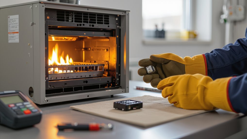
Ignition lockout occurs when the furnace repeatedly fails to light and the control board shuts off further ignition attempts to prevent unsafe operation.
Common causes include interrupted gas supply, ignition component failures, faulty flame sensing, or tripped safety switches.
The control board monitors ignition cycles and flame presence, then records failures and disables ignition until the fault is cleared or a manual reset is performed.
Definition of ignition lockout
A furnace ignition lockout is a safety condition in which the system stops attempting to light the burner after repeated unsuccessful ignition cycles.
It prevents unsafe operation by requiring manual or service intervention before restarting.
Understanding this term helps homeowners and technicians approach how to fix ignition lockout on furnace efficiently, recognizing the need for diagnostic steps, reset procedures, and informed repairs without bypassing safety features.
Common causes (gas supply, ignition system failures, flame sensing issues, safety switches)
Several common failures can trigger a furnace lockout, each tied to the system’s attempt to ignite and verify a safe flame.
Typical causes include interrupted gas supply (closed valve, regulator issues), ignition component failures (hot surface igniter, spark electrode), dirty or misaligned flame sensor, and tripped safety switches (limit, pressure, rollout).
Each prevents confirmed combustion, prompting lockout to protect the home.
How the furnace control board detects and responds to ignition failures
Detects and locks out when combustion isn’t verified. The furnace control board follows a strict sequence: it orders ignition (spark or hot surface), opens the gas valve, then monitors inputs from the flame sensor and safety switches for a valid flame signal within a set timeframe.
If no flame is detected, it shuts gas, increments a fault counter, signals an error, and enforces lockout after repeated failures.
Safety Precautions Before Troubleshooting
Before any troubleshooting begins, the reader is advised to recognize situations that require a licensed technician, such as persistent gas smells, repeated lockouts, or complex control issues.
Appropriate personal protective equipment should be used and basic gas-safety steps followed, including ventilating the area and avoiding open flames.
Finally, power and gas supply must be shut off according to the manufacturer’s instructions before accessing furnace components.
When to call a licensed technician
A homeowner should call a licensed technician when signs of persistent ignition failure, gas odor, electrical burning, or repeated lockouts occur, since these symptoms can indicate hazardous faults beyond routine user troubleshooting.
Additionally, seek professional help for unusual noises, visible damage to wiring or components, failed safety switches, or when diagnostic steps fail.
Timely service prevents escalation, guarantees code compliance, and protects occupants.
Personal safety gear and gas-safety steps
After recognizing situations that warrant professional help, the homeowner should equip themselves with proper personal protective gear and follow gas-safety steps when attempting basic troubleshooting.
Wear safety glasses, gloves, and a dust mask; guarantee good ventilation; keep open flames and sparks away; use a non-sparking tool if needed; have a working carbon monoxide detector; know how to evacuate and call emergency services if a gas odor is present.
Power and gas shutoff procedures
Several clear, deliberate steps should be taken to shut off power and gas before any furnace troubleshooting begins.
The technician locates and switches off the furnace circuit breaker at the main panel, confirms power absence with a meter, closes the gas shutoff valve near the appliance, and verifies gas is off by testing for odor or using a gas detector.
Lockout/tagout procedures are applied.
Quick Checklist: Immediate Steps to Reset Ignition Lockout
The technician begins with a brief checklist to address an ignition lockout.
First, power-cycle the furnace to clear transient faults and then reset the thermostat and control board per manufacturer instructions.
Finally, inspect error codes and LED indicators to guide any further action.
Power cycle the furnace
Power cycling the furnace is a quick, effective first step when an ignition lockout occurs: it resets the control board and clears transient faults that often trigger the safety lock.
To do this, switch the thermostat to off, turn off power at the furnace switch or breaker, wait 30–60 seconds, then restore power and set the thermostat to heat.
Observe for normal ignition.
Resetting the thermostat and control board
After power cycling the furnace, attention should shift to the thermostat and control board to verify settings and signals are correct.
The technician confirms thermostat mode, temperature setpoint, and wiring connections.
On the control board, verify jumper positions and secure connector seating.
Restore power and observe whether the thermostat call for heat initiates the ignition sequence; if not, proceed with further diagnostics.
Checking error codes and LED indicators
Several quick checks on the furnace’s control board and thermostat can reveal the cause of an ignition lockout.
The technician reads control-board LED patterns and thermostat error codes, consulting the manufacturer’s code chart. Record flashing sequences, note steady or blinking diagnostics, and power-cycle to confirm.
Use codes to isolate faults—ignition, flame sensor, gas valve, or wiring—and proceed with targeted repairs or professional service.
Step-by-Step Troubleshooting Guide
The technician begins with a systematic check of basic systems before progressing to component-level diagnostics.
Next steps include inspecting and cleaning the flame sensor, testing ignition parts, and evaluating the gas valve and pressure.
Finally, checks for flame rollout and safety switch operation complete the troubleshooting sequence.
Verify basic systems
Before proceeding to component-level checks, basic system conditions should be confirmed to rule out simple causes of ignition lockout. The technician or homeowner can quickly verify thermostat operation and batteries, the furnace switch and circuit breaker, and the gas valve and supply before moving on.
These steps save time and narrow the fault to either controls, power, or fuel.
- Thermostat set correctly and fresh batteries present
- Furnace power switch in the ON position
- Circuit breaker supplying the furnace not tripped
- Gas valve open and gas supply confirmed
Confirm thermostat settings and batteries
Check thermostat settings and replace weak batteries to rule out simple control failures before inspecting the furnace itself.
Verify mode is set to heat, desired temperature is above room temperature, and fan is on auto.
Replace batteries with fresh ones, then cycle the thermostat power.
Observe response: if the thermostat responds correctly but the furnace still locks out, proceed to electrical and ignition checks.
Ensure furnace switch and breaker are on
If the thermostat and batteries appear to function but the furnace remains unresponsive, attention should shift to power supply at the unit.
Verify the furnace’s dedicated switch (often near the air handler) is in the ON position.
Inspect the household breaker panel for a tripped circuit; reset the breaker if tripped.
Replace blown fuses.
If power indicators remain off, consult a qualified technician.
Check gas valve and supply
Confirm that the furnace is receiving fuel by inspecting the main gas shutoff and supply line for obvious issues.
Observe valve position, tightness, and visible damage.
Verify gas meter readings or pilot gas flow if accessible.
If the valve is closed, open it per manufacturer instructions.
If supply pressure seems low or leaks are suspected, stop and contact a qualified technician for testing and repair.
Inspect and clean the flame sensor
The technician locates the flame sensor near the burner assembly and notes its mounting and wiring before beginning work.
They follow a safe removal and cleaning procedure using a non-abrasive pad and appropriate precautions to avoid damage or shock.
After reinstalling the sensor and restoring power, the technician runs the furnace through ignition cycles to confirm proper operation.
Locate the flame sensor
Before handling any components, power to the furnace should be shut off at the thermostat and the service switch or breaker.
The technician locates the flame sensor by removing the access panel and visually inspecting the burner assembly. The sensor is a slender metal rod positioned near the gas burners, mounted on a small bracket with one wire attached.
Confirm its position before proceeding to cleaning.
Safe removal and cleaning procedure
Begin by cutting power to the furnace at both the thermostat and the service switch or breaker. Then ground oneself to prevent static discharge before touching components.
Remove access panel, locate and unscrew flame sensor using appropriate screwdriver, avoid bending. Gently slide sensor from burner assembly.
Wipe sensor rod with fine abrasive pad or alcohol-soaked cloth until metallic shine returns. Inspect mounting and wiring for corrosion; discard heavily damaged sensors.
Reinstalling and testing
Reinstall the cleaned flame sensor carefully, ensuring its rod aligns with the burner flame path and the mounting bracket seats flush against the assembly.
Reconnect wiring and tighten fasteners to manufacturer torque.
Restore power and gas, then initiate several ignition cycles while observing stable flame signal and continuous heat.
If lockouts persist, record error codes and proceed to sensor continuity check or controller diagnostics.
Test and troubleshoot the ignition components
Next, the ignition components are tested to isolate the source of the lockout.
The procedure covers checking both hot-surface and spark igniters, measuring resistance and continuity with a multimeter, and identifying when replacement is required.
Clear test results guide whether cleaning, adjustment, or installing a new igniter is necessary.
Checking the igniter (hot surface and spark)
One clear way to identify ignition faults is to test both the hot surface igniter and the spark electrode methodically.
Visually inspect for cracks, soot, or breaks. Observe glow timing for hot surface units and listen for spark clicks at the electrode during startup.
Verify proper mounting and clearances. Document findings and replace components showing visible damage or failing to operate as designed.
Measuring igniter resistance and continuity
Begin by preparing a multimeter and the furnace powered down and isolated from electrical and gas supplies.
Disconnect igniter leads and set multimeter to resistance (ohms) or continuity.
Probe igniter terminals gently; note resistance value and compare with manufacturer spec. Continuity beeps indicate circuit integrity.
Record readings, inspect wiring and connectors for breaks or corrosion.
Use results to guide further diagnostics.
Replacing a faulty igniter
To replace a faulty igniter, power and gas to the furnace must be fully isolated and the control panel opened to access the burner assembly.
The technician should document wiring, remove the broken igniter carefully, install a manufacturer‑specified replacement, secure mounting and connectors, then restore power and gas.
Perform ignition tests and observe several complete cycles to confirm reliable operation and no error codes.
Evaluate the gas valve and pressure
The technician listens for the sound of gas flow and the telltale click or whoosh of pilot ignition while observing burner response.
They then check line pressure and inspect the regulator and fittings for leaks, corrosion, or signs of sticking.
If pressures are out of range or regulator damage is suspected, the technician recommends contacting the gas utility or a qualified HVAC professional.
How to listen for gas flow and pilot ignition
Listen at the furnace control panel and near the pilot assembly for audible signs of gas flow and ignition: a faint hissing indicates gas reaching the pilot, while a brief whoosh or click suggests successful ignition.
Note timing with thermostat call, repeated attempts, and any delayed sounds. Absence of expected noises warrants valve, orifice, or ignition source inspection; proceed with safe shutdown and diagnostic checks.
Checking line pressure and regulator signs
Confidence in the fuel supply is essential before blaming ignition components.
Technicians measure line pressure at the furnace inlet with a manometer, comparing readings to manufacturer specifications. They inspect the regulator for dents, corrosion, or vent obstructions and check for pressure fluctuations when the system cycles.
Low or erratic pressure indicates supply or regulator issues requiring correction before further ignition troubleshooting.
When to call gas utility or pro
When should a gas utility or professional be contacted during gas valve and pressure evaluation?
If odors of gas, persistent low or fluctuating pressure, visible regulator damage, suspected leaks, or inability to isolate/restore safe supply occur, contact the gas utility immediately.
For complex diagnostics, sealed valves, or appliance-specific issues, retain a licensed HVAC or gas-service technician to prevent hazards and guarantee code-compliant repairs.
Examine flame rollout and safety switches
The technician locates the high-limit and rollout switches near the heat exchanger and burner compartment to assess potential flame rollout hazards.
Next, each safety switch is tested for continuity and manually reset where applicable to verify proper operation.
Any switch that fails testing or will not reset is replaced with a compatible rated component to restore safe furnace function.
Locate high-limit and rollout switches
Locating the high-limit and rollout switches requires opening the furnace access panel and visually inspecting the heat exchanger area and burner compartment for small rectangular or disk-shaped safety switches mounted near the combustion chamber or along the plenum.
Note their positions, wiring harness connections, and any visible damage, corrosion, or soot. Photograph locations for reference and consult the furnace schematic or service label to confirm switch types and mounting points.
Testing and resetting safety switches
Begin by de-energizing the furnace and confirming power is off before proceeding to test and, if appropriate, reset any high-limit or rollout switches.
Safety switches are sacrificial devices and must be inspected for physical damage, soot, or corrosion that indicate underlying combustion or airflow problems.
Use a multimeter to verify continuity, press manual reset if provided, then restore power and observe operation for recurrent trips.
Replacing defective safety switches
After verifying power is off and testing/resetting safety switches, attention shifts to replacing any that fail continuity or show physical damage.
The technician identifies the correct replacement part by model, notes wiring locations, disconnects terminals, removes mounting hardware, installs the new switch, reconnects wires, secures the unit, restores power, and retests operation and flame rollout to confirm normal furnace function.
Diagnose control board and wiring issues
The technician begins by reading the control board error codes to narrow possible faults and record any LED or digital fault patterns.
Next, wiring harnesses and connectors are inspected for loose pins, corrosion, burn marks, or broken insulation that could cause intermittent signals.
If persistent faults match documented failure patterns or physical damage is evident and repairs fail, the control board is replaced.
Reading control board error codes
When troubleshooting an ignition lockout, reading the furnace control board’s error codes provides a direct window into electrical and sequence faults.
Technicians reference the board’s LED blink patterns or digital display against the manufacturer’s code table to identify faults like ignition failure, flame loss, or sensor errors.
Log codes, note operating conditions, and reset only after corrective actions are planned to prevent repeated lockouts.
Inspecting wiring harnesses and connectors
Inspect wiring harnesses and connectors visually and by feel to locate loose pins, frayed insulation, corrosion, or heat damage that can interrupt signals between the control board and ignition components.
Secure loose connectors, reseat multi-pin plugs, and straighten bent terminals. Clean corrosion with contact cleaner and a small brush.
Replace damaged wires or terminal housings. Verify continuity and proper grounding before restoring power.
When to replace the control board
How can a technician determine that a furnace control board requires replacement rather than repair?
A control board should be replaced when visual damage, burnt traces, swollen capacitors, or repeated component failures are present.
If diagnostics show intermittent faults, error codes persist after testing, or schematics indicate integrated, nonserviceable components, replacement is safer and more cost-effective than attempted component-level repairs.
Troubleshooting by Furnace Type and Model Differences
Troubleshooting varies considerably by furnace type and model, so identifying whether a unit is single-stage, two-stage/modulating, millivolt, or standing pilot is the first step.
Single-stage systems commonly show simple ignition or control failures, while two-stage and modulating furnaces introduce additional sensors and control logic that can cause intermittent lockouts.
Millivolt and standing pilot systems rely on thermocouples or pilot integrity, so their diagnostics focus on pilot flame and low-voltage circuit issues.
Common issues with single-stage furnaces
Single-stage furnaces, which operate only at full capacity or off, commonly present a narrow set of recurring problems—short cycling, uneven heating, pilot or ignition failures, and limit-switch trips—because they lack modulation and advanced diagnostics.
Understanding these limitations helps pinpoint causes more quickly and guides whether simple repairs, component replacements, or a shift to a multi-stage or variable-speed system is warranted.
Common faults include faulty thermostats, clogged filters, draft issues, and failing flame sensors.
Common issues with two-stage and modulating furnaces
Recognize that two-stage and modulating furnaces introduce different failure modes than simpler single-stage units because they rely on additional control logic, variable-speed components, and more sensitive sensors.
Common issues include control board glitches, communication errors between thermostat and furnace, failed modulating gas valves, ECM/blower motor faults, and inaccurate pressure or temperature sensors.
Diagnostics require firmware-aware testing, component-level voltage/signal checks, and calibrated sensor replacement.
Differences for millivolt and standing pilot systems
After discussing failure modes unique to two-stage and modulating furnaces, attention shifts to older millivolt and standing-pilot systems, which operate on fundamentally different principles and consequently present distinct ignition lockout behaviors.
These systems rely on thermocouples/thermopiles or constant pilot flames, so lockouts often stem from weak millivolt generation, pilot contamination, or mechanical valve faults rather than electronic control failures.
Tools and Materials You’ll Need
A concise set of tools and materials is essential before attempting ignition lockout repairs.
Typical basics include a multimeter, screwdrivers, and cleaning pads, while having common replacement parts such as an igniter, flame sensor, and compatible thermostats on hand speeds repairs.
Recommended safety and diagnostic gear—gloves, eye protection, and a combustion analyzer or gas leak detector—should also be available.
Basic tools (multimeter, screwdriver, cleaning pads)
Several essential tools make diagnosing and resolving an ignition lockout straightforward: a reliable multimeter for electrical checks, a set of screwdrivers for panel access and component removal, and nonabrasive cleaning pads for contact and sensor maintenance.
A flashlight and insulated pliers aid safe inspection; labels and a small container keep fasteners organized. Proper PPE—gloves and eye protection—completes the basic kit.
Replacement parts to have on hand (igniter, flame sensor, thermostats)
With the basic inspection and cleaning tools in place, keeping a small set of common replacement parts on hand speeds repairs and reduces downtime.
Recommended spares include a compatible hot surface igniter, replacement flame sensor, and a basic programmable or mechanical thermostat matching the system.
Also stock wire terminals, heat-resistant silicone, and a multi-pack of furnace fuses to enable quick, accurate component swaps.
Recommended safety and diagnostic equipment
Before beginning work on an ignition lockout, the technician should assemble essential safety and diagnostic equipment to reduce risk and speed troubleshooting.
Required items include insulated gloves, safety glasses, multimeter with temperature probe, manometer, combustion analyzer, non-contact voltage tester, small mirror and flashlight, screwdrivers and nut drivers, clamp meter, and replacement fuses.
A service manual and lockout/tagout kit complete the list.
Cost Estimates and When Repair Becomes Replacement
Typical repair costs for ignition components, sensors, and control boards are outlined to help homeowners gauge expenses.
Indicators such as frequent breakdowns, rising energy bills, or repair costs approaching half the value of a new furnace suggest replacement may be more economical.
Labor and parts should be itemized separately when estimating total cost to compare repair versus replacement accurately.
Typical repair costs by component
Repair costs for ignition lockout issues vary by component and by whether a simple part swap or full replacement is required. Typical ballpark figures help plan repairs: ignition module $100–$300, flame sensor $40–$120, control board $200–$700. Labor varies; diagnostic fees add $50–$150. Consider warranty coverage before authorizing parts replacement.
| Component | Low | High |
|---|---|---|
| Ignition module | $100 | $300 |
| Flame sensor | $40 | $120 |
Signs that a furnace replacement is more economical
While small parts like ignition modules and flame sensors often warrant straightforward fixes, certain patterns of failures or escalating costs indicate replacement may be the more economical choice.
Frequent breakdowns, repeated major component failures, age over 15–20 years, poor energy efficiency, and repair costs approaching 50% of replacement value signal replacement.
Safety concerns or obsolete parts also favor installing a new furnace.
Estimating labor vs parts
A clear understanding of labor versus parts costs is essential when deciding whether to fix an ignition lockout or replace the furnace outright.
Technicians should itemize part prices, expected labor hours, and diagnostic fees.
Compare total repair cost to remaining system value and replacement quotes.
Include warranty differences and potential recurring failures; opt for replacement when repair approaches 50–70% of replacement cost.
Preventive Maintenance to Avoid Future Lockouts
Preventive maintenance focuses on simple, regular actions that reduce the chance of ignition lockouts.
A clear schedule for cleaning and inspecting key components, keeping filters and airflow unobstructed, and following an annual professional tune-up checklist can catch wear or faults before they trigger a lockout.
Implementing these steps helps extend system life and reduces emergency service calls.
Routine cleaning and inspection schedule
Establishing a routine cleaning and inspection schedule reduces the likelihood of ignition lockouts by ensuring key components are maintained before problems develop.
Visualize a quarterly checklist focusing on burners, igniter, gas valve, and vents. Recommended items:
- Inspect and clean burners for residue.
- Check and test igniter operation.
- Verify gas valve connections and seals.
- Clear visible obstructions from venting paths.
Air filter and airflow maintenance
Following the quarterly checklist, attention should turn to air filter and airflow maintenance, since restricted airflow is a common cause of ignition lockouts.
Replace or clean filters monthly or per manufacturer recommendations; use correct MERV rating.
Inspect vents, registers, and return grilles for obstructions, and verify blower operation.
Document filter changes and airflow measurements to detect trends and prevent future lockouts.
Annual professional tune-up checklist
Why schedule an annual professional tune-up? A technician inspects ignition components, gas pressure, pilot assembly, flame sensor, burners, venting, and safety controls.
They clean contacts, test thermostats, verify ignition sequences, replace worn parts, and calibrate system settings.
Documentation of findings and recommended repairs prevents future lockouts, improves efficiency, and extends furnace lifespan while ensuring safe, reliable operation.
Troubleshooting Scenarios and Real-World Examples
The following troubleshooting scenarios illustrate common ignition lockout patterns and their typical causes.
Examples include a furnace that cycles to lockout after several attempts, a unit that continuously clicks without lighting, and a system that lights briefly then locks out.
Each case will be paired with targeted checks and remedies to isolate and fix the underlying issue.
Scenario: Furnace cycles to lockout after a few attempts
A furnace that cycles through ignition attempts and then goes into lockout signals a persistent ignition or safety fault rather than an intermittent hiccup.
The technician inspects flame sensor cleanliness, electrode gap and alignment, gas valve operation, and ignition module diagnostics. They check venting and pressure switches for consistent status.
After identifying the failed component, they replace or repair it, then test multiple successful ignition cycles.
Scenario: Continuous clicking with no ignition
Following repeated ignition attempts that end in lockout, a different symptom—continuous clicking with no ignition—points to faults in the ignition or fuel delivery system rather than intermittent sensing errors.
Technicians should check for weak or misaligned spark/igniter, blocked gas valve or pilot orifice, faulty transformer or relay, and grounding issues.
Verify gas pressure and electrical continuity before replacing components.
Scenario: Furnace lights briefly then locks out
Observe when a furnace ignites briefly then immediately shuts down and goes into lockout, as this pattern narrows the fault to post-ignition sensing or fuel supply interruptions rather than initial ignition failure.
Inspect flame sensor for soot or misalignment, verify gas valve and pressure, check for intermittent airflow problems, monitor control board error codes, and test limit switches and rollout sensors for rapid false trips.
How to Document and Report Issues to a Technician
Before calling a technician, the homeowner should compile key details such as model and serial numbers, recent maintenance history, and the exact sequence of events leading to the lockout.
They should clearly record any error codes displayed, describe observed symptoms (no flame, clicking, gas smell), and note the times and conditions when the issue occurs.
Providing concise troubleshooting notes—steps already taken, results, and frequency—will help the technician assess and resolve the problem more efficiently.
What information to gather before the service call
When preparing to call a technician, compile clear, specific details about the furnace’s behavior, the exact sequence of events leading to the lockout, and any recent service or changes to the system.
Include model, serial number, installation age, recent fuel or power interruptions, thermostat actions, observable noises, odors, flame appearance, and whether safety devices were tripped.
Note any DIY attempts and timestamps.
How to record error codes and symptoms
Several specific details make error codes and symptom descriptions useful to a technician: the exact alphanumeric code displayed, the number and rhythm of LED flashes, the sequence and timing of audible alarms, and a concise account of what the furnace was doing immediately before and after the fault.
Note timestamped observations, sensor readings, recent maintenance, and any intermittent behaviors; photograph displays and log multiple occurrences.
Sample troubleshooting notes to share with a pro
Provide a concise, organized summary that a technician can read quickly: include the exact error code or LED flash pattern, timestamps for each occurrence, the sequence of events leading up to the lockout, recent changes or maintenance, ambient conditions (temperature, power interruptions), and any measured sensor readings or voltages.
Then list: observed symptoms, actions attempted, component IDs, multimeter readings, furnace model/serial, photo references, and contact availability.
Final Safety Reminders and Next Steps
After completing a repair or reset, the technician verifies that all controls operate normally and that there are no gas odors or unusual noises before leaving.
A follow-up inspection is recommended and should be scheduled within a few weeks or according to manufacturer guidance to confirm long-term safety and performance.
For additional guidance, the homeowner is directed to manufacturer manuals, reputable HVAC resources, and local safety codes.
Immediate actions after repair or reset
Confirm the furnace operates normally and that all safety devices respond as expected before leaving the area.
Verify no gas smells, guarantee vents and combustion air pathways are clear, and restore any removed access panels.
Record work performed, parts replaced, and reset parameters.
Advise occupants of observations and temporary restrictions.
Monitor system through initial heating cycles to confirm stability and absence of error codes.
Scheduling follow-up inspections
One to two follow-up inspections should be scheduled after an ignition lockout repair to verify ongoing safe operation and to catch delayed or intermittent faults.
A qualified technician should confirm correct ignition cycles, sensor function, and venting integrity, and document findings.
Schedule inspections at one and three months post-repair or sooner if symptoms recur.
Keep records for warranty and safety tracking.
Resources for learning more
Where can a homeowner find reliable guidance on furnace ignition lockouts? Trusted sources include manufacturer manuals, certified HVAC technician guides, and safety organizations that emphasize procedures and limits.
Recommended next steps focus on learning, safe tools, and when to call professionals.
- Manufacturer service manual
- EPA/NFPA safety bulletins
- Certified HVAC training resources
- Local licensed technician consultations
Conclusion
The technician concluded that ignition lockout, a modern safeguard, resembles a stubborn troubadour refusing encore; it signals repeated ignition failures and demands methodical attention. Readers are reminded to follow safety protocols, document findings like an archivist, and attempt basic resets only if competent. If faults persist, professional service is advised to prevent gas hazards and equipment damage. Prudence and routine maintenance reduce recurrence and extend furnace life.