How to Set Gunmetal Valves: Step-by-Step Guide for Precise Adjustment and Maintenance
To set gunmetal valves accurately, follow this step-by-step guide for precise adjustment and maintenance. Start by isolating and depressurizing the system while wearing appropriate personal protective equipment (PPE). Check existing clearances using calibrated feeler gauges or dial indicators. Loosen the locknuts, make small adjustments, and recheck each clearance, ensuring you torque to the specified settings. Clean all seating surfaces and replace any worn packing or seats before reassembling the valve. Finally, restore service and document the adjustments for future reference. For detailed instructions and troubleshooting, continue reading.
What “gunmetal valves” refers to and when adjustment is needed
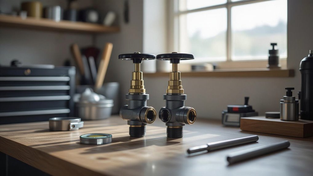
Gunmetal valves are corrosion‑resistant fittings commonly used in plumbing, marine, and industrial steam systems. Their construction and typical applications determine appropriate adjustment procedures.
Indicators that a valve requires setting or maintenance include persistent leakage, noisy or sticking operation, loss of system pressure, or visible wear on components.
Before any work begins, personnel should follow lockout/tagout, depressurize and drain systems, and wear gloves, eye protection, and hearing protection as required.
Definition and common applications of gunmetal valves
A durable bronze alloy used for valves in plumbing, steam, and hydraulic systems, gunmetal refers to high-copper, tin-and-zinc-bearing cast metal prized for corrosion resistance and machinability.
Gunmetal valves serve fittings, gate, globe, and check valves in marine, industrial, and residential systems.
The guide explains how to set a gunmetal valves for reliable sealing, flow control, and long-term service life.
Signs that valves need setting or maintenance
Inspectors should look for common indicators that gunmetal valves require setting or maintenance: persistent leaks at packing or joints, difficulty turning the handwheel or stem stiffness, irregular or noisy flow (chatter, banging, or whistling), visible corrosion or pitting on seating surfaces, and inconsistent downstream pressure or flow rates.
Additional signs include slow response, leakage past the seat, vibration, and reports of reduced system efficiency.
Safety precautions and required personal protective equipment
Before any adjustment, personnel should confirm the component type and service conditions: gunmetal valves are bronze alloy fittings commonly used for seawater, steam, and general-purpose industrial services. Adjustments are warranted when leaks, stem stiffness, seat leakage, abnormal noise, or compromised system performance are observed.
Personnel must isolate systems, depressurize and drain lines, lockout/tagout, and verify zero energy.
Required PPE: gloves, eye protection, hearing protection, steel-toe boots, and chemical-resistant clothing when applicable.
Tools, materials, and preparations before adjusting valves
Before beginning valve adjustment, a concise checklist of essential tools (wrenches, feeler gauges, torque wrench, soft-faced mallet) and recommended spare parts/consumables (gaskets, packing, lubricant) should be gathered.
The technician should perform pre-adjustment inspections, confirm system isolation and lockout/tagout, and verify pressure is relieved and drains are opened.
Baseline measurements and concise documentation of current settings, clearances, and serial/position identifiers must be recorded prior to any work.
Essential tools checklist
A compact set of tools and materials is required to adjust gunmetal valves accurately and safely:
- Precision feeler gauges, calibrated micrometer or gap gauge.
- Adjustable spanner, valve wrench, and torque driver for controlled tightening.
- Clean lint-free cloths, non-silicone lubricant, and corrosion inhibitor.
- Inspection mirror, flashlight, and magnetic pickup for small components and visibility.
Recommended spare parts and consumables
Gathering the correct spare parts and consumables guarantees valve adjustments proceed without interruption and minimizes the risk of damage.
Recommended items include common replacement seats, O-rings, lubricants compatible with gunmetal, and fasteners matching original specifications.
Keep spare gaskets, packing, anti-seize compound, and threadlocker on hand.
Inventory quantities based on valve count and service history.
- Replacement seats
- O-rings
- Compatible lubricants
- Gaskets and packing
Pre-adjustment inspections and system isolation steps
Inspect the valve assembly and surrounding system components to verify integrity, cleanliness, and absence of pressure or hazardous media.
Confirm isolation valves, blinds, or double block-and-bleed arrangements are correctly positioned and tagged.
Drain and vent trapped sections, secure lockout/tagout, and depressurize slowly.
Gather necessary tools, PPE, sealing materials, and calibration aids.
Ascertain adequate lighting and access for adjustment.
Recording baseline measurements and documentation
With isolation confirmed and the system depressurized, the technician should record baseline measurements and prepare documentation before any valve adjustments.
Record valve positions, stem travel, operating torque, pressure readings, temperature, and visual condition.
Log tool identifiers, calibration status, date/time, and responsible personnel.
Photograph assemblies and mark reference points.
Store records in maintenance log and attach to work order for traceability.
Valve anatomy and terminology relevant to adjustment
The section outlines the core components of gunmetal valves—such as bodies, stems, seats, and packing—and their roles in sealing and flow control.
It distinguishes actuation types (manual handwheel, lever, and automated actuators) and explains how each influences clearance and adjustment procedure.
It also covers common markings, sizing conventions, and flow-direction indicators needed to interpret valve orientation and performance.
Core components of gunmetal valves and their functions
A gunmetal valve consists of several precisely machined parts—body, bonnet, stem, seat, disc (or plug), packing, and actuator—that together control fluid flow and seal under pressure; understanding each component’s role and naming conventions is essential before attempting any adjustment.
The body houses flow paths, the bonnet provides closure and alignment, the stem transmits motion, the seat seals against the disc, packing prevents leakage, and the actuator imparts movement.
Types of valve actuation and how they affect adjustment
Understanding each component’s role in a gunmetal valve leads naturally to examining how motion is imparted—valve actuation—which directly shapes adjustment methods.
Actuation types—manual (handwheel, lever), electric, pneumatic, and hydraulic—demand different torque, travel limits, and feedback.
Adjustment procedures vary: manual needs clearances and locking, powered requires actuator calibration, stroke setting, torque limits, and safe isolation before tuning to guarantee reliable seating and sealing.
Interpreting valve markings, sizes, and flow direction
Because correct adjustment depends on knowing what each mark and dimension signifies, technicians must read valve markings, size stamps, and flow arrows before any calibration or disassembly.
Identify body material, pressure class, port size, model number, and serial code. Note flow direction arrows and inlet/outlet designations.
Interpret trim and seat codes to match replacement parts and confirm correct orientation for safe, accurate adjustment.
Step-by-step procedure to set clearance on gunmetal valves
The technician begins by securing and depressurizing the system before proceeding.
Access to the valve is gained and covers are removed so the current clearance can be measured with the appropriate gauges.
Locking mechanisms are loosened for incremental adjustments, then clearance is verified and locknuts are retightened to specification.
Step 1 Secure and depressurize the system
Begin by isolating the cylinder from all energy sources and verifying zero pressure throughout the system.
Lock out and tag out electrical, pneumatic, and hydraulic supplies.
Drain residual fluids and bleed lines to atmospheric.
Secure mechanical restraints to prevent movement.
Confirm with calibrated gauges or pressure-test ports.
Record isolation status and post visible warning signs before any further valve work proceeds.
Step 2 Accessing the valve and removing covers
Access the valve assembly only after isolation and verification steps are complete, using appropriate PPE and tools to prevent contamination or damage.
Remove external guards, nameplates, and actuator housings methodically, retaining fasteners and seals in labeled containers.
Clean mating surfaces, inspect covers and O-rings for wear, and document orientation.
Confirm lighting and stable support before proceeding to expose the valve core.
Step 3 Measuring current clearance with appropriate gauges
One should verify and record the existing valve clearance before adjustment by using calibrated feeler gauges, a dial indicator, or thickness gauges appropriate to the valve’s specification; this establishes a baseline and prevents over-correction.
The technician notes each clearance, compares to manufacturer tolerances, inspects seating surfaces for wear, repeats measurements at multiple cam positions, and documents results for reference during subsequent adjustment steps.
Step 4 Loosening locking mechanisms and making incremental adjustments
With the engine cool and measurements recorded, the technician loosens the valve locks or locknuts just enough to permit adjustment while preventing unintended rotation.
This controlled slack is achieved using the correct socket, wrench, or spanner and applying steady, even torque to avoid marring gunmetal surfaces.
Small, measured turns of the adjuster screw alter clearance; each increment is checked with the gauge and the adjuster held steady.
Step 5 Verifying clearance and retightening locknuts to spec
Begin by rechecking each valve clearance in the same order used during measurement, placing the feeler gauge between the rocker and valve stem while the adjuster is held stationary to confirm the specified gap.
If correct, hold the adjuster and tighten the locknut to the manufacturer’s torque while preventing adjuster rotation.
Reinspect clearance after tightening and adjust if necessary.
Step 6 Reassembling covers and returning system to service
Restore the valve covers and ancillary components in the reverse order of disassembly, ensuring all mating surfaces are clean and gasket or O-ring seals are properly seated.
Torque cover fasteners to specification using a calibrated tool. Reconnect removed sensors, lines, and covers.
Reinstall safety guards and fill or bleed fluids as required.
Verify vents, breather paths, and access panels are secured before returning the system to service.
Step 7 Post-adjustment testing and recording final settings
Perform a systematic post-adjustment test to confirm each valve clearance holds under operating conditions and to record the final settings for maintenance history.
The technician runs the engine or system through warm-up and load cycles, rechecks clearances at temperature, listens for abnormal noise, and inspects for leaks.
Final measurements, adjustment notes, torque values, date, and technician ID are logged in the maintenance record.
Procedures for different valve scenarios and types
Procedures vary with valve design and operating mechanism, so the technician first identifies whether the unit is a gate, globe, piston/plunger, or a gearbox/actuator‑driven assembly.
Manual gate and globe valves require different stem and seating checks than piston‑style units, which need specific clearance measurements for plungers or pistons.
Temperature at the time of adjustment—hot versus cold—also dictates compensation techniques and final clearances.
Adjusting manually operated gate and globe valves
Adjusting manually operated gate and globe valves requires verifying valve type, system conditions, and planned flow characteristics before any mechanical intervention.
The technician isolates the line, relieves pressure, and inspects packing, stem threads, and seating surfaces.
Gate valves need full travel checks; globe valves require incremental seating adjustments to balance flow and minimize seat wear.
Reassemble, test for leaks, and document settings.
Setting clearances on piston- or plunger-style valves
Begin by identifying the valve type, manufacturer specifications, and operating conditions, since piston- and plunger-style valves require clearance settings tailored to geometry, pressure, and service (e.g., steam, hydraulic, or gas).
Inspect wear, measure stem-to-seat and piston-to-bore clearances, compare to spec, and document.
Adjust shims or replace components to achieve tolerance.
Reassemble, perform pressure checks and record results.
Adjusting valves with gearbox or actuator drives
When working with gearbox- or actuator-driven valves, technicians must verify drive alignment, travel limits, and torque settings before making any trim or linkage adjustments.
Inspect couplings, backlash, and mounting fasteners. Confirm actuator calibration and control signals.
Use appropriate handwheel or manual override procedures to position stems.
Adjust linkages, stops, and limit switches incrementally, then recheck sealing, stroke, and torque to guarantee reliable operation.
Hot vs cold adjustment techniques and temperature compensation
Temperature differentials critically influence valve clearances and seating behavior, so technicians must choose hot or cold adjustment methods based on valve type, material thermal expansion, and operating conditions.
Cold adjustments suit uniform materials and static seals; hot adjustments compensate running expansion for tight seats. Use manufacturer specs, calibrated feeler gauges, and temperature correlation charts.
Implement shims or preload changes for repeatable compensation across cycles.
Troubleshooting common problems during valve setting
When problems arise during gunmetal valve setting, clear diagnostic steps guide the technician through stuck or seized valves, persistent leakage after adjustment, noisy operation or vibration, and inaccurate gauge readings.
Suggested remedies include systematic inspection, targeted cleaning or lubricant application, seal replacement or retorquing, balancing and isolation checks for vibration, and verification or recalibration of instruments.
Each issue should be addressed methodically and documented to confirm resolution and prevent recurrence.
Valve stuck or seized diagnostic steps and remedies
Diagnose a stuck or seized gunmetal valve by systematically isolating mechanical, corrosion, and contamination causes:
Check for visible corrosion, seize marks, or foreign debris; verify rocker arm and camshaft movement; confirm valve stem freeplay with a feeler or gentle tapping; and guarantee retaining components (keepers, springs) are intact and properly seated.
Apply penetrating oil, gentle heat, or controlled mechanical persuasion; replace damaged stems, guides, or springs and re-lap seating if needed.
Persistent leakage after adjustment causes and fixes
Inspecting persistent valve leakage after adjustment requires a focused, methodical approach to identify whether the issue stems from improper clearance, seating defects, or secondary component failures.
Check clearances with feeler gauges, remeasure runout and valve face wear, and inspect seats for pitting or corrosion.
Verify rocker geometry, guide wear, and valve spring tension.
Replace or refinish defective parts and retest under operating pressure.
Noisy operation or vibration after setting
Listen for abnormal sounds and feel for vibrations immediately after valve adjustments, as they often signal misalignment, incorrect clearances, or secondary component issues.
Inspect rocker arms, guides, and fasteners for looseness or wear. Verify clearances per specification and retorque connections. Check for foreign debris, bent stems, or spring fatigue.
If vibration persists, isolate by running individual cylinders to pinpoint the source.
Inaccurate readings from gauges or instruments
When valve-clearance readings appear inconsistent or implausible, the technician should first confirm the accuracy of the measuring instruments and the conditions under which measurements were taken.
Calibrate gauges, verify zero, and repeat readings at controlled temperatures.
Check for damaged probes or dirty feeler gauges. Document results and use a known-good reference instrument to validate.
- Calibrate
- Repeat under controlled conditions
- Inspect tools
- Cross-check
Maintenance schedule and best practices for long-term valve performance
A clear maintenance schedule specifying inspection and adjustment intervals helps keep gunmetal valves operating reliably.
Routine lubrication, corrosion protection, cleaning steps, and defined parts replacement criteria (with spares inventory planning) minimize unplanned downtime.
Consistent recordkeeping—logging date, findings, adjustments, lubricants used, and parts replaced—supports trend analysis and future service planning.
Recommended inspection and adjustment intervals
Routine inspections and timed adjustments at defined intervals guarantee gunmetal valves maintain sealing integrity and operational reliability.
Inspect quarterly for external wear, corrosion signs, and actuator response; perform functional tests and minor clearances.
Semiannual checks should include valve travel, seat contact, and fastener torque.
Annual thorough overhaul verifies dimension tolerances, replaces degraded components, and documents settings for trend analysis and preventive planning.
Lubrication, corrosion protection, and cleaning routines
Establish a scheduled program of lubrication, corrosion protection, and cleaning tailored to the service environment, valve design, and material compatibility to preserve sealing surfaces and moving parts.
Specify lubricant types, application methods, and frequencies; use corrosion inhibitors compatible with gunmetal; employ non-abrasive cleaning agents and techniques.
Inspect for residue or contamination after service; document procedures and adjust intervals based on wear, operating conditions, and performance trends.
Parts replacement criteria and inventory planning
Define clear replacement criteria and maintain a prioritized spare-parts inventory to minimize downtime and extend gunmetal valve life.
Components are replaced based on wear limits, leakage thresholds, and service intervals; critical spares are stocked first.
Inspection-driven scheduling balances cost and reliability.
- Seat and disc thresholds
- Stem and packing wear limits
- Fastener and gasket availability
- Lead time and supplier redundancy
Recordkeeping templates and what to log after each service
A standardized recordkeeping template guarantees consistent capture of key data after every service, enabling trend analysis and informed maintenance decisions for gunmetal valves.
The template logs date, technician, valve ID, settings (clearances, torque), measurements, wear observations, parts replaced, lubrication type/quantity, test results, and next scheduled service.
Digital storage, version control, and periodic review support lifecycle tracking and proactive intervention.
Safety, compliance, and industry standards to follow
The section outlines applicable codes and standards governing metallic valve maintenance, including inspection intervals and documentation requirements.
It emphasizes adherence to lockout-tagout procedures and confined-space protocols to protect personnel during adjustment and removal.
It also covers proper handling, disposal, and recycling of removed gunmetal components to meet environmental and regulatory obligations.
Relevant codes and standards for metallic valve maintenance
Compliance with established codes and standards secures metallic valve maintenance protects personnel, preserves system integrity, and meets regulatory obligations. Practitioners should follow ASME, API, ISO, and local regulations for inspection, testing, documentation, and material traceability. Adherence secures interoperability, safety, and audit readiness.
| Standard | Focus |
|---|---|
| ASME | Design/pressure |
| API | Performance/testing |
| ISO | Quality/system |
| Local regs | Permits/compliance |
Lockout-tagout and confined-space considerations
Because energy sources and enclosed atmospheres pose acute hazards during valve work, strict lockout-tagout (LOTO) procedures and confined-space controls must be established before any entry or maintenance begins.
Personnel must verify isolation, deenergization, and zero-energy state; post clear tags and locks.
Permit-required confined-space protocols, continuous atmospheric monitoring, rescue plans, trained attendants, and documented compliance with OSHA and local regulations are mandatory.
Environmental disposal and handling of removed components
Following verification of isolation and confined-space controls, attention shifts to safe handling and disposal of removed components to prevent environmental release and regulatory violations.
Components contaminated with oil, solvents, or heavy metals must be segregated, labeled, and stored in appropriate containers.
Disposal must follow local hazardous-waste regulations, recycling protocols, and manufacturer guidance.
Documentation, chain-of-custody records, and employee training guarantee compliance and accountability.
Cost, time estimates, and when to call a professional
Typical labor and parts costs for setting gunmetal valves are outlined with common time estimates to guide budgeting.
Situations such as severe corrosion, inaccessible installations, or uncertainty about system compatibility are identified as triggers for specialist intervention.
A concise checklist for hiring a qualified valve technician—credentials, experience with gunmetal, insurance, and references—is provided to aid selection.
Typical labor time and parts cost ranges
Labor estimates for replacing or setting gunmetal valves vary with valve size, system complexity, and access, but most straightforward residential jobs take 1–3 hours while commercial or confined-space work can require a full day or more.
Typical parts costs range from $20–$250 for seals, stems, or small valves; larger or OEM assemblies run $300–$1,200.
Labor rates depend on region and technician skill.
Conditions that require specialist intervention
Several specific conditions warrant calling a specialist to set or replace gunmetal valves: evidence of corrosion through the valve body or bonnet, seized or severely worn stems, compromised seals causing persistent leaks, valves integral to high-pressure or hazardous systems, and installations in confined or hard-to-access spaces.
Typical specialist costs range widely; expect diagnostics plus parts and labor, often requiring safety permits and multi-hour onsite work.
Checklist for hiring a qualified valve technician
After recognizing conditions that require specialist intervention, the next step is selecting a qualified valve technician using a concise, practical checklist.
Criteria include certification, insurance, and references; estimated hourly rates and typical job durations; clear scope and warranty; and escalation triggers for immediate professional response.
- Certification and insurance
- Rates and time estimates
- Scope, warranty, terms
- Emergency response criteria
Conclusion
Gunmetal valves require careful, regular attention to preserve machinery performance and safety. Studies show improper valve clearance causes up to 20% greater fuel consumption in small engines, underscoring the impact of precise adjustment. By following prescribed preparation, measurement, and tightening procedures, technicians extend component life and reduce failures. Routine inspections, adherence to safety standards, and timely professional help when uncertainties arise guarantee reliable, efficient operation and lower long‑term costs.