How to Check a Type K Thermocouple: Simple Tests and Troubleshooting Tips
To check a Type K thermocouple, start with a visual inspection for any signs of damage such as corrosion, kinks, exposed wires, or discolored junctions. Then, use a digital multimeter to verify continuity and measure millivolts at a known cold-junction temperature, comparing these readings to Type K reference tables. Look for signs of failure, such as infinite resistance (indicating an open circuit) or near-zero resistance (indicating a short circuit), and be aware of any drift or intermittent readings. Finally, address potential issues like loose connectors, grounding problems, or cold junction compensation (CJC) errors. Additional steps for calibration, repair, and replacement may be necessary.
How to Quickly Determine if a Type K Thermocouple Is Working
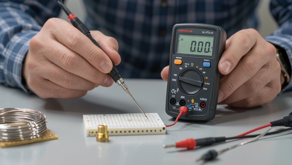
Before any measurement, visual cues such as corrosion, frayed wires, or inconsistent temperature readings at the same location can indicate a faulty Type K thermocouple.
A quick check with a digital multimeter—measuring millivolts at a known temperature or comparing cold-junction–compensated readings to expected values within the manufacturer’s tolerance—confirms whether output is within spec.
If the output is well outside tolerance or shows open/short behavior, the sensor should be considered failed; marginal or intermittent results warrant further troubleshooting of connections and cold-junction compensation.
Signs a thermocouple may be faulty before testing
How can one spot early indicators that a Type K thermocouple may be failing?
Visual cues include corrosion, frayed insulation, crushed or kinked probe, and discolored junctions.
Intermittent readings, slow response, or unexplained process temperature drift suggest degradation.
Loose fittings, connector oxidation, or exposed wires warrant replacement.
For guidance on diagnosis, consult resources on how to check thermocouple type k.
Fast verification using a digital multimeter (expected results and tolerance)
After spotting visual damage or erratic behavior, a quick checks with a digital multimeter (DMM) provides a fast, objective way to verify a Type K thermocouple.
Measure millivolts at cold junction ambient; compare to Type K reference chart. Open-circuit infinite resistance indicates break; short near zero suggests internal short.
Acceptable tolerance typically ±1–2°C equivalent (≈±0.04–0.08 mV) for quick field checks.
When to call it failed vs. when to continue troubleshooting
When is a Type K thermocouple considered beyond practical repair versus worth further investigation?
Inspect physical damage, contamination, or broken wires; severe corrosion, crushed junctions, or melted insulation justify replacement.
If readings deviate beyond tolerance after cold-junction compensation, or intermittent/open circuits appear, replace.
Continue troubleshooting for connector faults, cold-junction errors, wiring continuity, and calibration before condemning the sensor.
Safety Precautions and Required Tools
Before testing, the technician should follow personal safety and electrical precautions to prevent burns, shocks, and instrument damage.
A concise tools-and-equipment checklist—including a compatible multimeter, K-type thermocouple adapter or pins, insulated probes, and protective gear—ensures the job proceeds smoothly.
Recommended multimeter settings and probe types (millivolt or thermocouple input, appropriate range, and insulated, low-thermal EMF probes) should be confirmed before measurements begin.
Personal safety and electrical precautions
Several fundamental safety measures must be observed to reduce the risk of electric shock, burns, and equipment damage while testing a Type K thermocouple.
The tester should de-energize circuits, verify absence of voltage with a meter, wear appropriate PPE (insulated gloves, eye protection), avoid loose clothing, maintain dry hands and workspace, and isolate thermocouple leads to prevent shorting or contact with live conductors.
Tools and equipment checklist
Having addressed personal safety and electrical precautions, the focus shifts to assembling the proper tools and protective equipment needed for accurate and safe thermocouple testing.
Required items include sturdy gloves, eye protection, insulated tools, and clean connection leads. Proper calibration references and tag labels are helpful.
Recommended checklist:
- Insulated hand tools
- Protective gloves and goggles
- Clean, labeled leads
- Reference calibration source
Recommended multimeter settings and probe types
Select a multimeter capable of millivolt resolution and a temperature-function mode (or use a dedicated thermocouple thermometer) to guarantee accurate Type K readings; pair it with probes rated for thermocouple use or with minimized contact resistance (spring-loaded or banana-to-miniature adapters) and insulated leads to maintain safety and signal integrity.
Set the meter to millivolts or thermocouple input, enable cold-junction compensation if available, and use firm, clean probe contacts.
Understanding Type K Thermocouple Basics
A Type K thermocouple is a nickel-chromium/nickel-alumel pair commonly used for general-purpose temperature measurement in labs, kilns, engines, and HVAC systems.
It produces a small millivolt signal proportional to the temperature difference between the measurement and reference junctions via the thermoelectric (Seebeck) effect.
Proper use requires attention to polarity (positive chromel, negative alumel), standard color coding, and compatible connectors to guarantee correct readings.
What a Type K thermocouple is and typical applications
Type K thermocouples are temperature sensors made from chromel (nickel-chromium) and alumel (nickel-aluminum) alloys that generate a voltage proportional to temperature differences between their junctions.
They suit wide temperature ranges (approx. −200°C to 1260°C), offering good durability and fast response.
Common applications include furnaces, kilns, HVAC systems, engines, industrial processes, and scientific instrumentation requiring robust, general-purpose temperature measurement.
How Type K generates voltage with temperature (thermoelectric principle)
Following the overview of composition and uses, the operating principle of the K thermocouple rests on the thermoelectric (Seebeck) effect: when two dissimilar metal conductors—chromel and alumel—are joined at one end (the measuring junction) and held at a different temperature than their other ends (the reference junction), a voltage is produced that is proportional to the temperature difference.
That electromotive force varies predictably with temperature, enabling measurement.
Polarity, wire colors, and connector standards
Polarity in K thermocouples determines which conductor is positive (chromel) and which is negative (alumel), and correct identification is essential for accurate temperature readings.
Chromel is conventionally positive; alumel negative.
Standard color coding varies by region: in IEC, chromel is yellow, alumel red; in ANSI, signs may differ.
Connectors are polarized to prevent reversal; matching standards avoids measurement errors.
Step-by-Step Tests to Check a Type K Thermocouple
The procedure begins with a visual inspection of the thermocouple sheath, junction and leads for damage or corrosion.
Next, continuity and resistance measurements are taken with a multimeter and interpreted against expected values, including open-circuit millivolt checks with cold-junction compensation.
Finally, practical verification uses known-temperature references — an ice bath, boiling water, or a calibrator/temperature source — to compare measured millivolts to standard Type K tables.
Visual inspection procedure (wires, sheath, junction)
Begin by examining the thermocouple assembly from end to end, looking for obvious damage to the wires, protective sheath, and measurement junction.
Note discoloration, kinks, cuts, corrosion, or melted insulation. Verify junction integrity and sheath compression. Record observations for repair or replacement decisions.
- Surface cuts or abrasions
- Insulation breakdown
- Junction deformation
- Corrosion or contamination
Continuity/resistance test steps and interpretation
After the visual inspection confirms no obvious mechanical faults, continuity and resistance testing verifies conductor integrity and detects hidden breaks or shorts.
Using a multimeter set to continuity or low-ohms, probe each thermocouple leg to the junction and return lead. Expect low, stable resistance; infinite or fluctuating readings indicate open circuits.
Very low resistance to sheath suggests a short; replace or repair accordingly.
Cold-junction compensation and measuring open-circuit voltage
Several key steps secure accurate open-circuit voltage readings by addressing cold-junction compensation (CJC) before measuring a Type K thermocouple.
The technician verifies the reference junction temperature is known or compensated by the instrument, avoids thermal gradients at connector points, and uses proper insulated leads.
Then the open-circuit millivolt output is recorded, referenced to the CJC value, and compared to expected thermocouple tables.
Using a multimeter to measure millivolts at specific temperatures (ice bath and boiling water test)
To verify a Type K thermocouple’s output, the technician uses a digital multimeter set to millivolts and measures the open-circuit voltage with the junction immersed in known-temperature baths—typically an ice-water mix (~0°C) and boiling water (~100°C at local atmospheric pressure).
Readings are compared to Type K thermoelectric tables (mV per °C). Significant deviation indicates sensor damage, wiring issues, or poor junction contact.
Using a thermocouple calibrator or temperature source for accuracy checks
Begin by selecting a calibrated thermocouple calibrator or a stable temperature source capable of covering the desired measurement range; these instruments provide a controlled reference that isolates the thermocouple and its wiring from environmental variables.
Connect the Type K probe to the calibrator, set target temperatures, allow stabilization, record readings, and compare against reference values.
Note deviations, repeat checks, and document uncertainty for calibration decisions.
In-circuit testing while connected to instrumentation
Perform in-circuit tests with the thermocouple connected to its instrumentation to verify system-level behavior without removing the probe.
Observe live readings, compare against a reference or known temperature, and monitor response time and stability.
Check cold-junction compensation, wiring integrity, and ground loops.
Use instrument diagnostics and log data for transient faults.
Isolate inputs if discrepancies persist to pinpoint sensor versus electronics.
Interpreting Test Results and Common Fault Patterns
Test results are compared against expected voltage or resistance ranges to distinguish open-circuit (no reading), short-circuit (near-zero resistance), and intermittent connection symptoms.
Observed drift, non-linear output, or consistent offset indicates aging, calibration errors, or thermoelectric degradation.
Visual inspection for corrosion, oxidation, and mechanical damage helps correlate electrical faults with physical causes.
Open circuit, short circuit, and intermittent connection symptoms
When a Type K thermocouple fails, its electrical behavior typically falls into three recognizable patterns—open circuit, short circuit, or intermittent connection—each producing distinct voltage and temperature-reading symptoms that help isolate the fault.
Open circuit shows infinite resistance and no millivolt output; short circuit reads near zero resistance and bogus zeroed temperatures; intermittent connection causes sporadic voltage spikes, fluctuating readings, and reproducible instability under vibration.
Drift, non-linear output, and calibration errors
Recognize that drift, non-linear output, and calibration errors produce subtler, progressively worsening symptoms than open or short circuits and consequently require pattern-based interpretation of test data.
Persistent offset, slope changes, or temperature-dependent deviations indicate drift or calibration loss.
Compare readings against a calibrated reference across the range, plot residuals, and use statistical trends to distinguish sensor aging, connector-induced nonlinearity, or instrument calibration faults for targeted correction.
Effects of corrosion, oxidation, and mechanical damage
Exposed to heat, moisture, and contaminants, Type K thermocouples develop corrosion and oxidation at junctions and along conductors.
Mechanical shocks or vibration cause insulation breaches, conductor fractures, and distorted junctions. Such damage yields increased resistance, intermittent or drifting signals, cold-junction errors, and reduced sensitivity.
Visual inspection, continuity checks, and comparative readings isolate affected segments; replacement or protected reinstallations restore reliability.
Troubleshooting Procedures for Common Issues
The technician should begin by inspecting and repairing loose connectors and crimped joints, and decide whether a damaged probe or extension wire warrants replacement.
Attention must be paid to electrical noise and grounding problems that can corrupt readings, while verifying and correcting cold-junction compensation settings.
Systematic checks and stepwise isolation of components help pinpoint the root cause and confirm the fix.
Repairing loose connectors and crimped joints
Begin by inspecting all connector interfaces and crimped joints for movement, corrosion, or visible deformation that could introduce intermittent resistance.
Tighten loose terminals, clean corrosion with a contact cleaner, and reform deformed crimps.
If crimp barrels are compromised, cut back wire and install new properly sized ferrules or solder joints per manufacturer guidance.
Re-test continuity and insulation before returning to service.
When to replace the probe or extension wire
After tightening and cleaning terminals, persistent measurement errors or intermittent signals indicate the problem may lie in the probe or extension wire rather than connectors.
Replace the probe when insulation damage, kinks, corrosion at the junction, or visible breach exists.
Replace extension wire if continuity tests fail, resistance is unstable with movement, or insulation cracks exposing conductors.
Prioritize replacement when calibration drift persists.
Dealing with electrical noise and grounding problems
Several common issues—electrical noise, ground loops, and poor shielding—can produce unstable or offset readings from a Type K thermocouple and should be addressed systematically.
Inspect shielding, separate thermocouple leads from power cables, use twisted-pair or shielded extension wire, and verify single-point grounding.
Add ferrite beads or filtering if needed and isolate the sensor from noisy equipment.
Retest after each change.
Correcting cold-junction compensation errors
When a Type K thermocouple reports an offset that persists despite proper sensor wiring and shielding, incorrect cold-junction compensation (CJC) is a likely cause and should be checked next.
Verify CJC reference temperature input, confirm sensor junction and CJC element share proper connection points, and inspect compensating cable integrity.
Replace or recalibrate the transmitter/module CJC if errors remain, then re-test for accuracy.
Preventive Maintenance and Best Practices
Preventive maintenance for Type K thermocouples focuses on simple installation choices, regular inspections, and proper storage to extend sensor life.
Recommended practices include correct sheath selection and strain relief at installation, scheduled visual and electrical checks with periodic calibration, and handling procedures that prevent contamination or mechanical damage.
Following these guidelines reduces drift, failures, and measurement uncertainty.
Installation tips to prolong sensor life
Position the thermocouple to minimize mechanical stress, chemical exposure, and thermal cycling at the junction.
Install with adequate sheath support, correct insertion depth, and secure routing of extension wires.
Avoid sharp bends, vibration sources, and corrosive atmospheres.
Use compatible sheath materials and protective fittings.
Replace sacrificial protectors as needed.
- Support and strain relief
- Correct insertion depth
- Chemical compatibility
- Vibration isolation
Routine inspection and calibration schedule recommendations
Although thermocouples are inherently durable, a structured routine of inspections and calibrations is essential to maintain accuracy and detect degradation before failures occur.
Establish monthly visual checks for insulation, connectors, and sheath integrity; perform functional verification against a reference every 3–6 months; recalibrate annually or after any process upset exceeding specified tolerances.
Document findings, trends, and corrective actions for continuous improvement.
Storage and handling guidelines for Type K thermocouples
Store Type K thermocouples in a clean, dry environment at stable room temperature and away from corrosive vapors or direct sunlight to prevent oxidation and insulation degradation.
Handle by the sheath or connector, avoiding strain on junctions and wires. Coil loosely, using non-abrasive ties.
Label with calibration and service dates. Keep separate from magnetic or conductive contaminants to maintain accuracy and longevity.
Comparison of Test Methods and Tools
Different test instruments offer distinct advantages and limitations when verifying a Type K thermocouple’s accuracy and response. The brief table below highlights key comparisons between a multimeter, a thermocouple calibrator, and a thermometer to guide method selection. Choice depends on required accuracy, test conditions, and available equipment.
| Tool | Typical Strengths/Limitations |
|---|---|
| Multimeter | Portable and inexpensive; limited temperature accuracy without cold-junction compensation |
| Thermocouple calibrator | High accuracy and simulation capability; requires training and is costlier |
| Thermometer (reference) | Useful for field reference and direct temperature checks; may lack thermocouple-specific diagnostics |
Multimeter vs. thermocouple calibrator vs. thermometer comparison
When verifying a Type K thermocouple, technicians typically choose among a digital multimeter, a dedicated thermocouple calibrator, or a reference thermometer, each offering distinct trade-offs in accuracy, convenience, and cost.
A multimeter is inexpensive and suitable for continuity/voltage checks but less accurate.
Calibrators provide precise simulated outputs and logging.
Reference thermometers yield high-accuracy temperature comparisons but require stable contact and calibration.
Troubleshooting Scenarios and Solutions
The following troubleshooting scenarios present common failure modes and step-by-step diagnostics for a Type K thermocouple.
Each scenario—low readings only under load, intermittent readings when the probe is moved, and no voltage after high-temperature exposure—includes targeted checks such as continuity and cold-junction verification, mechanical inspection and strain-relief testing, and visual inspection for oxidation or melting plus insulation resistance measurements.
Technicians can use these procedures to isolate wiring, junction, sensor, and installation faults before replacing the probe.
Scenario: Thermocouple reads low only under load diagnostic steps
Identify load-related discrepancies by noting that the thermocouple reads correctly at idle but drops under applied load. This pattern indicates issues that manifest only when current or thermal stress increases and narrows the fault possibilities to connections, internal resistance changes, or external interference.
Inspect terminals for corrosion, tighten and reflow joints, measure loop resistance under load, verify sheath integrity, and isolate external electromagnetic sources.
Scenario: Intermittent readings when moved diagnostic steps
Check for mechanical stress and loose connections first, since a Type K thermocouple that reads intermittently when moved most often indicates a break or intermittent contact in the probe wiring, terminal block, or connector.
Visually inspect the cable, strain relief, and connectors. Gently flex along the length while monitoring output.
Replace or reterminate any section that causes fluctuation; test again for stability.
Scenario: No voltage output after high-temperature exposure diagnostic steps
After prolonged exposure to high temperatures, a Type K thermocouple that shows no millivolt output often suffers from metallurgical degradation, melted insulation, or a broken junction.
Diagnostics should consequently focus on visual inspection of the sensing tip, cable, and connector, continuity and polarity checks, and evaluating whether materials have oxidized or fused.
If damage is found, replace the probe or splice with correct alloys and high-temperature insulation.
When to Replace vs. When to Repair
Decision to replace or repair hinges on cost, expected downtime, and the required reliability for the application.
If replacement is chosen, selection should consider thermocouple materials, sheath type and thickness, and the needed accuracy and calibration class.
Repairs are preferable only when they restore original performance quickly and economically without compromising long-term reliability.
Cost, downtime, and reliability considerations
Cost-benefit analysis guides whether a failed Type K thermocouple should be repaired or replaced, weighing component cost, expected downtime, and the probability of future failures.
Critical-process environments favor replacement for predictable reliability despite higher upfront cost.
For noncritical applications, repair or field splice can be economical if inspection confirms limited degradation.
Include spare inventory, labor rates, and failure impact in decisions.
How to select a replacement Type K thermocouple (materials, sheath, accuracy)
When selecting a replacement Type K thermocouple, prioritize match to the application’s thermal, chemical, and accuracy requirements: choose probe materials and sheath alloys that resist the process environment (e.g., stainless steel for general use, Inconel for oxidizing or corrosive atmospheres, ceramic for extreme temperatures).
Consider sheath diameter, response time, and insulation. Specify calibration class and tolerance.
Repair if damage is localized; replace when drift, contamination, or structural failure occurs.
Quick Reference Charts and Conversion Tools
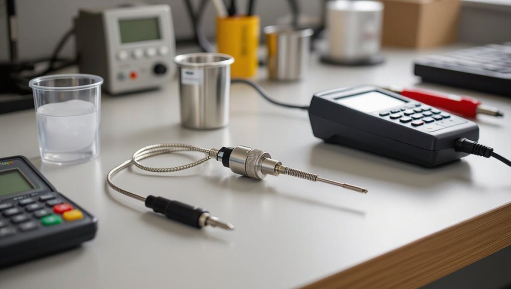
A concise table of common Type K millivolt-to-temperature reference points helps technicians verify readings quickly against expected values.
Such charts typically list millivolt outputs at key temperatures (e.g., 0°C, 100°C, 500°C) and can speed troubleshooting when calibrating instruments.
Portable conversion tools or smartphone apps that implement the Type K polynomial provide fast, accurate cross-checks in the field.
Common Type K millivolt-to-temperature reference points
Reference tables and quick-conversion tools simplify the process of translating Type K thermocouple millivolt outputs into temperature readings by providing commonly used calibration points and interpolation shortcuts. A concise chart highlights standard millivolt-to-temperature pairs for verification and linear interpolation checks. Use the table below for routine comparisons and spot checks.
| mV | °C | Note |
|---|---|---|
| 0.0 | 0 | cold junction |
| 2.5 | 60 | common check |
| 10.0 | 250 | high-end spot |
Conclusion
In sum, the guide leaves the reader equipped to judge a Type K thermocouple’s health with methodical clarity. Like a seasoned mechanic listening for an engine’s cough, one can distinguish cold-junction issues, open circuits, and drifted outputs through simple continuity checks, millivolt measurements, and calibration comparisons. Emphasizing safety, appropriate tools, and clear pass/fail criteria guarantees informed decisions about repair versus replacement, minimizing downtime and costly misdiagnosis.