
How to Vent a High Efficiency Furnace Safely: Step-by-Step Guide and Code Tips
To safely vent a high-efficiency furnace, use approved PVC/CPVC or stainless pipe, ensuring proper slope, sealed joints, and correct termination clearances. Follow these essential steps: shut off power and gas, confirm combustion-air requirements, size condensate drains, and calculate equivalent vent lengths, including elbows. Use approved adhesive for joints, and provide supports and insulation to prevent sagging and freezing. Test pressure switches and check for leaks, and ensure you have the necessary permits for inspection. Continue reading for detailed step-by-step procedures, code specifics, and troubleshooting tips.
How to Vent a High Efficiency Furnace Safely: Quick Overview and Key Takeaways
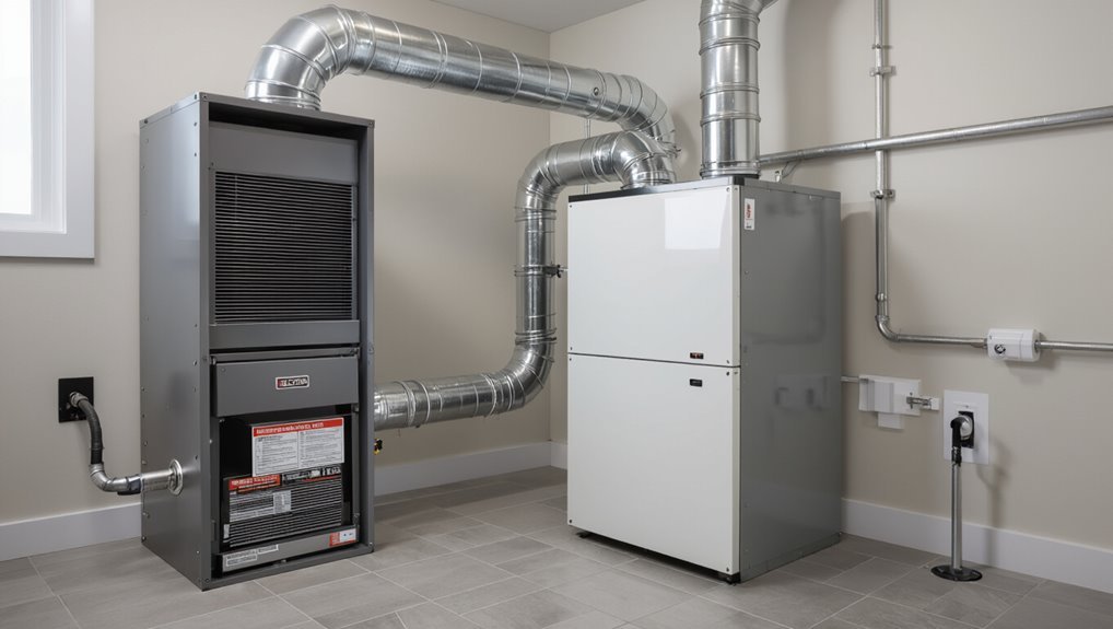
Before beginning any venting work, the reader should shut off the furnace, cut power and gas supplies, guarantee proper ventilation, and wear appropriate protective gear.
Basic tasks may be suitable for experienced DIYers, but complex flue routing, signs of corrosion or persistent carbon monoxide readings, and local code concerns warrant calling a licensed professional.
These takeaways prioritize immediate safety and clear criteria for when to stop and seek expert help.
Immediate safety precautions before you begin
Shut off the furnace power and gas supply, then confirm the area is clear and well-ventilated before any work begins.
Inspect for carbon monoxide detectors, combustible materials, and visible corrosion.
Use proper PPE—gloves, eye protection, and a respirator if dusty.
Review manufacturer instructions and local codes for how to vent high efficiency furnace installations.
Have tools organized and a fire extinguisher nearby.
When to call a professional instead of DIY
When should a homeowner stop DIY work and call a licensed HVAC professional?
A professional is required for complex vent routing, gas connections, combustion-air issues, permits, or when local code compliance is uncertain.
Call also if condensate drainage, draft testing, or manufacturer warranty coverage is involved, or if the installer lacks experience.
Safety, legal liability, and proper system performance justify hiring licensed help.
Understanding High Efficiency Furnace Venting Basics
High efficiency furnaces extract more heat from combustion, producing cooler, moisture-rich exhaust that requires different venting than conventional units.
Common venting options include direct venting, power venting, and PVC systems with condensate drains, each suited to specific install conditions.
Proper vent design must manage both exhaust flow and condensate to prevent corrosion, blockages, and backdrafting.
What makes a furnace “high efficiency” and why venting differs
A high-efficiency furnace achieves greater fuel-to-heat conversion through condensing technology and advanced combustion control, producing more usable heat from the same amount of fuel than older, non-condensing models.
These units extract latent heat from exhaust, creating condensate and cooler flue gases. Venting differs because materials, slope, and sealing must accommodate acidic condensate, lower temperatures, and often forced exhaust pressures to guarantee safe, code-compliant operation.
Types of venting systems for high efficiency furnaces (direct vent, power vent, PVC condensate drain)
Because condensing furnaces produce cooler, acidic flue gases and often use induced-draft fans, their venting options differ from older systems and call for specialized components.
Common types include direct vent sealed-combustion systems drawing outdoor air and exhausting directly, power vent systems using fans to overcome static pressure, and PVC or CPVC plastic piping for corrosive condensate and cool flue gas routing, sized per manufacturer and code.
How exhaust gases and condensate behave in high efficiency systems
Several factors determine how exhaust gases and condensate behave in a high-efficiency furnace: cooler flue temperatures, moisture formation from combustion, and induced-draft airflow created by the fan.
Cooler gases condense into acidic water that must be drained or neutralized. Low-temperature, PVC-compatible venting prevents corrosion.
Proper slope, trap, and materials guarantee condensate removal while maintaining draft integrity and preventing flue gas leakage.
Tools, Materials, and Codes Required
The section outlines the essential tools and PPE needed for a safe venting job, including pipe cutters, proper sealants, and respiratory and eye protection.
It summarizes common vent materials—PVC, CPVC, and stainless steel—highlighting each material’s temperature, corrosion, and joint requirements.
It also stresses checking applicable building codes and the furnace manufacturer’s venting specifications before beginning work.
Essential tools and PPE for safe vent installation
Proper preparation begins with assembling the right tools, materials, and personal protective equipment to guarantee a safe, code-compliant high-efficiency furnace vent installation.
Required items include drill, hole saws, pipe cutter, level, tape measure, sealant gun, and corrosion-resistant fasteners.
PPE: safety glasses, gloves, hearing protection, respirator if cutting indoors, and sturdy footwear.
Verify tools meet local code and manufacturer specifications before work.
Common vent materials and their properties (PVC, CPVC, stainless steel)
After assembling tools and PPE, attention turns to selecting vent materials that meet performance, longevity, and code requirements.
PVC offers corrosion resistance, low cost, and ease of joining for low-temperature condensate drains.
CPVC tolerates higher temperatures and resists chemical degradation.
Stainless steel provides superior strength, heat tolerance, and longevity for exposed runs or condensate-contact applications where rigidity and durability are required.
Relevant building codes and manufacturer specifications to check
Because venting decisions affect safety, efficiency, and code compliance, installers must verify local building codes, fuel-specific regulations, and the furnace manufacturer’s venting instructions before cutting, joining, or routing any piping.
Required checks include clearances, approved materials, termination locations, and draft/pressure requirements.
Consult authorities having jurisdiction and retain installation manuals for inspection.
- Local building and plumbing codes
- Fuel/utility provider rules
- Manufacturer venting diagrams and limits
- Vent material and connector approvals
Pre-Installation Assessment and Planning
Before beginning work, the installer verifies the furnace location and required clearances to guarantee safe access and combustion air.
They calculate allowable vent length and equivalent lengths for elbows to confirm proper draft and fan performance.
They also size the condensate drain with appropriate slope and select a termination point that meets safety requirements and local code.
Inspecting furnace location and clearances
A thorough inspection of the furnace location and required clearances establishes whether the chosen site meets safety, serviceability, and code requirements.
Inspectors verify combustion air access, adequate working space on all sides, minimum clearances from combustible materials, and routing options for venting.
Check for nearby ignition sources, access panels, floor stability, and proper drainage for condensate to prevent corrosion and service complications.
Calculating vent length, elbows, and equivalent length limits
Calculating vent length, the number and type of elbows, and the resulting equivalent length is critical to ensuring proper draft and condensate drainage for a high-efficiency furnace.
The installer reviews manufacturer charts for maximum linear and equivalent lengths, counts standard versus long-turn elbows, and adds fittings’ equivalent feet.
If limits are exceeded, reroute, increase diameter per spec, or install an approved inline fan to maintain code-compliant performance.
Sizing condensate drain and slope requirements
Proper sizing of the condensate drain and establishing the correct slope are essential steps in pre-installation planning to prevent backups, promote reliable drainage, and comply with appliance and plumbing codes.
Determine drain diameter per manufacturer and local code, typically 3/8–3/4 inch OD tubing or 1/2–1 inch pipe.
Maintain continuous slope (1/8–1/4 inch per foot), avoid traps, and provide accessible cleanouts.
Locating optimal termination point for safety and code compliance
When selecting the furnace termination point, the installer must balance combustion air and exhaust clearance requirements, local code restrictions, and practical site constraints to ascertain safe operation and regulatory compliance.
The installer evaluates prevailing wind, nearby openings, roof and grade clearances, service access, and potential condensation impact. Documented measurements and local code verification ascertain the chosen location minimizes re-entrainment and satisfies manufacturer specifications.
Step-by-Step Vent Installation Procedure
Before beginning work, the technician isolates power and gas to the furnace and prepares the unit for vent connections.
Measurements are taken and vent pipe sections are cut, fitted, and secured with approved adhesives or sealants, with all seams and joints properly fastened.
The installer then connects the condensate trap and drain, and fits any required draft inducer or power vent components per manufacturer instructions.
Preparing the furnace and shutting power/gas
Shut down the furnace and isolate its fuel and electrical supplies to create a safe work environment.
The technician labels disconnects, shuts the gas valve, and turns off circuit breakers. After verifying zero power with appropriate testers and confirming gas isolation, they place lockout/tagout devices.
Vent access panels are opened only after purging residual pressure and confirming the unit is cold and inert.
Measuring, cutting, and fitting vent pipes
Begin by confirming the vent route and required materials, noting total length, number of fittings, and clearances to combustibles and obstructions.
Measure twice, mark pipe runs, and account for slope where required.
Cut pipe with appropriate tools, deburr edges, and test-fit each section and fitting.
Verify proper alignment for smooth condensate flow and maintain specified clearances before final connection.
Securing seams, joints, and using approved adhesives/sealants
With pipe runs confirmed and test-fitted, attention shifts to making seams and joints gas- and watertight.
Installer inspects mating faces, deburrs edges, and aligns fittings. Approved stainless steel clamps or screws secure mechanical joints; manufacturer-approved high-temperature silicone or HVAC-rated sealants coat seams per instructions.
Use only listed products and follow curing times. Document materials for code inspection and future maintenance.
Installing condensate trap and drain line
Installers prepare the condensate trap and drain line by verifying compatible materials, correct trap orientation, and proper slope before permanent attachment.
They position the trap immediately at the furnace condensate outlet, install a cleanout access, and route the drain to an approved disposal point with continuous fall.
Connections are secured, tested for leaks, and insulated where freezing or freezing-back risks exist to guarantee reliable drainage.
Installing draft inducer or power vent components (if applicable)
After confirming the condensate trap and drain are secure and leak-free, attention shifts to the draft inducer or power vent assembly that regulates combustion airflow and exhaust pressure.
The installer mounts the unit per manufacturer orientation, verifies electrical and pressure switch connections, seals motor and blower flanges with gaskets, insulates condensate paths, and tests startup, observing proper rpm, pressure differential, and safe operation before proceeding.
Routing vent to termination and installing termination cap
Begin by laying out the vent run from the draft inducer or power vent toward the chosen exterior termination, ensuring the path follows the manufacturer’s clearances, slope, and support requirements.
Cut and join pipe sections with approved fittings and seals, secure supports at specified intervals, and maintain the required upward slope to the condensate drain.
Flash and seal the exterior penetration, then install the manufacturer-approved termination cap and verify airtight connections.
Restoring power/gas and initial startup checks
Restore utilities only after confirming all vent connections, seals, supports, and clearances are complete and tools or debris have been cleared from the work area.
Reapply electrical and gas supplies per manufacturer instructions.
Observe furnace for proper ignition, flame pattern, and absence of gas odor.
Verify exhaust flow at termination, check for leaks, monitor pressure switches and condensate drainage.
Document settings and report anomalies.
Testing, Commissioning, and Verification
The installer conducts leak tests on both combustion and condensate systems and confirms vent and combustion-air airflow meet specifications.
Pressure switch and safety-control operation are checked to guarantee reliable shutdown and safe operation.
Installation details and photographic evidence are documented for certification and inspection.
Leak testing for combustion and condensate systems
Inspecting for leaks in combustion and condensate systems is a critical step in commissioning high-efficiency furnaces to confirm safe operation and code compliance.
Technicians perform pressure and smoke tests on vent joints, flue connections, and PVC terminations, plus visual and dye tests on condensate lines and traps.
Documented results, immediate repairs of detected leaks, and retesting guarantee integrity, prevent CO exposure, and avoid water damage.
Verifying proper combustion air and vent airflow
Begin by confirming that combustion air sources and vent airflow meet manufacturer specifications and code requirements before placing the furnace into normal operation.
Measure intake and exhaust velocities, static pressures, and vent termination clearances.
Verify balanced airflow, unobstructed intakes, and proper condensate drainage.
Record readings, compare to acceptable ranges, adjust vent sizing or intake openings as needed, and document compliance for commissioning records.
Checking for correct pressure switch and safety control operation
After confirming combustion air and vent airflow meet specifications, attention shifts to verifying pressure switch and safety control operation to guarantee reliable furnace shutdown under fault conditions.
Technicians simulate blocked vent and induced draft failure to confirm switches open and control logic cuts fuel and ignition.
Verify tubing integrity, vacuum levels, switch actuation points, and interlock responses per manufacturer and code requirements before final commissioning.
Documenting installation and taking photos for inspection
A complete set of installation records and clear photographs provide an objective basis for municipal inspection, warranty claims, and future service.
The installer documents vent routing, joint types, condensate drain, clearances, termination location, and label data plate.
Photographs show overall system, close-ups of seals, supports, and slope.
Include date-stamped images, technician name, checklist, measured draft/pressure readings, and any corrections made.
Common Problems, Troubleshooting, and Solutions
Common signs of improper venting include persistent condensation, unusual odors, and visible corrosion on vent components.
Technicians should troubleshoot backdrafting, spillage, and flue blockages by inspecting termination points, pressure differentials, and draft patterns. Then check for condensate backups or frozen drain lines as potential causes.
If vent material incompatibility is suspected, replacing incompatible piping or components with manufacturer-approved materials typically resolves recurring failures.
Signs of improper venting (condensation, odors, corrosion)
Several clear signs indicate a high-efficiency furnace is venting improperly: persistent condensation on venting components, unusual or sour odors near the appliance, and visible corrosion on flues or connections.
Additional indicators include water stains around vent terminations, rust flakes in condensate drains, and damp insulation or mold odors in adjacent spaces.
Prompt inspection prevents deterioration and safety risks.
Troubleshooting backdrafting, spillage, and flue blockages
Many issues with high-efficiency furnace venting—backdrafting, combustion spillage, and flue blockages—stem from airflow disruptions, improper termination, or accumulation of debris and condensate.
Inspect vent termination, cap condition, and clear obstructions. Measure draft with manometer during operation.
Check for competing exhausts, negative house pressure, and damaged vent pipe joints.
If spillage or strong CO indications occur, shut down equipment and call a certified technician.
Fixes for condensate backups and frozen drain lines
Addressing condensate backups and frozen drain lines requires prompt, targeted actions to prevent water damage and system shutdowns.
Technicians should clear traps, flush lines with warm water or a vinegar solution, inspect and replace clogged condensate pumps, and verify proper slope and insulation on drain piping.
Add heat tape where permitted, confirm condensate neutralizer condition, and test system operation after repairs.
When vent material incompatibility causes failures
After resolving condensate backups and frozen drains, attention should shift to the venting system: incompatible vent materials can cause corrosion, heat damage, or improper exhaust flow that leads to system failures and safety hazards.
Inspect material compatibility with combustion condensate and flue temperatures, replace non-approved plastics or metals, seal joints correctly, and follow manufacturer and code requirements to prevent leaks, backdrafting, and premature equipment failure.
Code Compliance, Permits, and Inspection Tips
Before beginning work, the homeowner or installer should confirm local permit requirements and gather documentation to streamline the inspection.
During the inspection, the inspector will verify key code provisions such as vent clearances, proper termination location and elevation, and secure support and sealing of the vent run.
It is also important to check manufacturer venting specifications, since improper installation can void the furnace warranty.
Typical permit requirements and how to prepare for inspection
Obtain the correct permits and documentation before starting work, since high-efficiency furnace venting generally falls under local mechanical and building codes and often requires a permit.
Contractors or homeowners should submit plans, equipment specs, and vent routing.
Schedule inspections early, keep receipts and manufacturer instructions on site, and guarantee access to the installation area.
Be ready to correct any noted deficiencies promptly.
Key code provisions to verify during inspection (clearances, termination location, support)
With permits secured and inspection scheduled, the inspector will focus on specific code provisions that directly affect safety and performance: required clearances from combustibles and service access, the approved location and horizontal/vertical placement of the vent termination relative to doors, windows, openings and property lines, and the firmness and corrosion resistance of supports and fastenings along the entire vent run.
Additionally, seals, slope, and routing avoiding ignition sources are checked.
Manufacturer warranty considerations tied to venting
If a venting installation deviates from the manufacturer’s instructions or from code requirements, warranty coverage for the furnace—particularly for heat exchangers, induced-draft components, and corrosion-related failures—can be voided.
Manufacturers often require authorized installers, specified materials, proper clearances, and documented inspections.
Homeowners should retain installation records, obtain required permits, and verify compliance to preserve warranty rights and simplify potential claims.
Maintenance and Long-Term Safety Practices
A clear maintenance plan helps preserve vent performance and prevent hazards over time.
It should specify a routine inspection schedule with key items to check, seasonal tasks such as clearing condensate lines and checking seals, and criteria for replacing corroded or brittle components.
Recognizing signs of aging—rust, cracks, persistent leaks, or degraded connections—triggers timely replacement to maintain safe operation.
Routine inspection schedule and what to look for
Because routine inspections catch small problems before they escalate, a consistent schedule—quarterly visual checks with annual professional servicing—forms the backbone of long-term safety for high-efficiency furnace venting.
Inspect termination caps, condensate drains, vent pipe joints, and seals for corrosion, blockage, or sagging.
Listen for unusual noises, note odors, verify proper draft and secure fasteners.
Document findings and remediate promptly.
Seasonal maintenance tasks to prevent vent issues
Prepare for seasonal shifts by scheduling targeted maintenance tasks that address common causes of venting problems in high-efficiency furnaces.
Inspect and clear condensate drains, check seals and joints for corrosion or looseness, remove debris from terminations, confirm proper slope and support of PVC runs, test draft and pressure switches, and verify condensate traps.
Document actions and set reminders for next seasonal check.
When to replace vent components and signs of aging
When vent components show visible wear, recurring leaks, or persistent performance declines, replacement should be scheduled promptly to maintain safety and efficiency.
Technicians inspect corrosion, cracks, separator damage, warped or detached joints, and degraded seals. Excessive soot, chronic condensation, or unusual odors indicate failure.
Follow manufacturer intervals and local code; replace plastic, PVC, or metal sections showing compromise to prevent carbon monoxide risks.
Comparison of Venting Options and When to Choose Each
Different vent materials and configurations offer distinct trade-offs in durability, cost, and suitability for specific furnace types, and selecting the right combination affects both safety and performance. Below is a concise emotional prompt to contrast material options (PVC, CPVC, stainless) and venting methods (power, direct, chimney) for practical decision-making. The following table frames key impressions to guide choice and urgency.
| Material/Method | Strength | Feeling |
|---|---|---|
| PVC vs CPVC vs Stainless | Cost, corrosion resistance, temp limits | Reassurance vs caution |
| Power vent vs Direct vs Chimney | Performance, installation complexity | Confidence vs concern |
| Suitability and cost trade-offs | Long-term maintenance needs | Practicality vs worry |
PVC vs CPVC vs Stainless Steel: pros, cons, cost, and suitability
Although all three materials—PVC, CPVC, and stainless steel—serve as viable venting options for high-efficiency furnaces, they differ markedly in temperature tolerance, chemical resistance, durability, installation complexity, and cost.
PVC is low-cost and easy to install but limited by heat and chemical exposure.
CPVC tolerates higher temperatures and corrosive condensate.
Stainless steel offers maximum durability, corrosion resistance, higher cost, and more complex installation.
Power vent vs direct vent vs chimney: performance and use-cases
After comparing materials for condensate and exhaust piping, the next decision centers on how the furnace actually expels combustion gases: via a power vent, a direct vent, or a traditional chimney.
Power vents use fans for flexible routing and sealed combustion; direct vents draw outdoor air and exhaust coaxially, ideal for airtight homes.
Chimneys rely on natural draft, requiring proper sizing and frequent inspection; choose based on site, code, and efficiency.
Practical Tips, Safety Reminders, and Best Install Habits
A concise set of practical tips and reminders helps guarantee venting is safe, efficient, and code-compliant. The following points highlight a quick safety checklist, frequent installer errors to avoid, and simple measures that can improve energy performance. Proper attention to these items reduces risk and prolongs furnace life.
- Verify clearances, slope, materials, and termination location per manufacturer and local code.
- Avoid common mistakes: inadequate support, wrong pipe type, improper seals, and poor condensate routing.
- Seal and insulate where required to prevent heat loss and condensation issues.
- Schedule regular inspections and follow manufacturer maintenance intervals to sustain efficiency.
Quick checklist for a safe vent installation
When installing a high-efficiency furnace vent, following a concise checklist confirms the system operates safely and efficiently.
Verify correct vent type and materials, maintain proper slope and support, seal all joints, ascertain correct termination location and clearances, confirm combustion air provision, pressure-test for leaks, follow manufacturer and code specifications, and document installation details.
Perform final inspection and functional testing before commissioning.
Common installer mistakes to avoid
Recognize and correct common installer mistakes early to prevent safety hazards and costly rework: improper vent type or incorrect material, inadequate slope or support, poor joint sealing, and incorrect termination placement are frequent issues that compromise combustion air, draft, and condensate drainage.
Inspect clearances, follow manufacturer specs and codes, secure joints with approved connectors, maintain slope for condensate, level supports, and verify termination orientation and obstruction-free discharge.
Energy-saving tips related to venting and furnace efficiency
Because venting directly affects combustion efficiency and heat recovery, thoughtful vent design and maintenance yield measurable energy savings and longer equipment life.
Use properly sized, insulated PVC or stainless liners to minimize heat loss and condensation. Keep runs short, avoid unnecessary bends, and seal joints.
Schedule annual inspections, clear intake/exhaust obstructions, and follow manufacturer and code requirements to maintain peak performance.
Conclusion
A single neighbor, returning from a late shift, notices the new PVC termination cap glowing faintly in the porch light—proof of work done right. The homeowner, who once feared carbon monoxide, now sleeps easier, coincidentally passing the inspector the same morning plans were finalized. Small choices—correct pipe, proper slope, sealed joints—align by chance and care, transforming technical compliance into quiet safety. The furnace vents; the household exhales, trusts restored.
