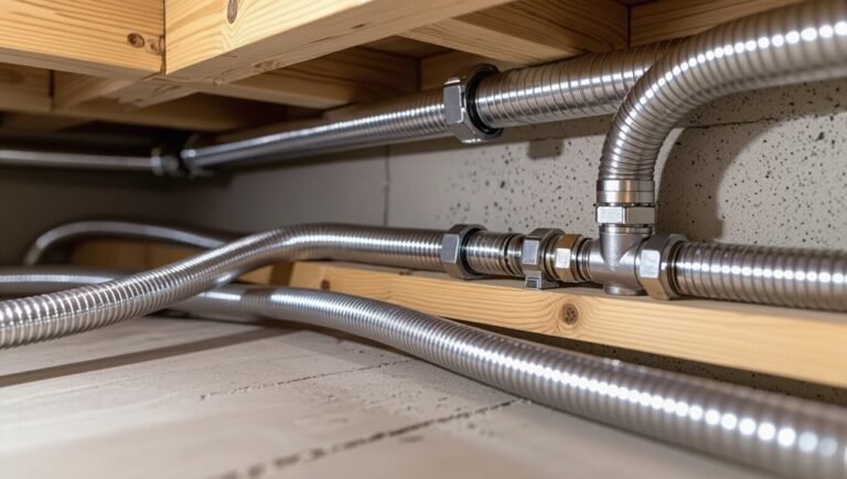
How to Use Gas Line Pipe Sizing Safely: Step-by-Step Guide for Homeowners
To safely size gas line pipes for your home, start by confirming local codes and regulations. Assess the BTU demand of your appliances, measure the run lengths, and check the supply pressure. Convert any fittings to their equivalent lengths, calculate the total frictional loss, and consult approved sizing tables to select the smallest compliant diameter. Use the correct materials, conduct leak tests, and adhere to pressure testing and ventilation requirements. Keep thorough records of your calculations and any necessary permits. This guide includes step-by-step procedures, example calculations, safety checks, and code references to ensure you complete the job correctly and safely.
What Homeowners Need to Know Before Working on Gas Line Pipe Sizing
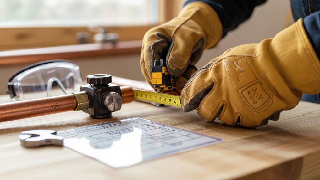
Homeowners should recognize that correct gas pipe sizing is critical for both safety and appliance performance, as undersized lines can cause leaks, incomplete combustion, or pressure drops.
They must also follow legal and code requirements—including local ordinances and standards such as NFPA 54 and relevant IRC provisions—and obtain required permits before altering gas systems.
For complex layouts, multi-appliance installations, or any uncertainty, a licensed plumber or certified gas fitter should be contacted.
Why proper gas pipe sizing matters for safety and performance
Correct pipe sizing directly affects both safety and appliance performance: undersized lines can cause incomplete combustion, carbon monoxide risk, and pressure drop, while oversized lines may lead to unnecessarily high installation costs and routing difficulties.
Homeowners learning how to use gas line pipe sizing safety should recognize proper sizing prevents flame instability, appliance damage, leaks, and trips in supply.
Accurate calculations optimize efficiency and reduce hazards.
Legal, code, and permit considerations (local codes, NPFA 54, IRC references)
Regulations and permits govern virtually every aspect of gas line sizing and installation, so anyone planning work must first verify local code requirements and obtain required permits.
Homeowners should reference NFPA 54 (National Fuel Gas Code) and the IRC provisions adopted locally, confirm municipality amendments, follow inspection and testing mandates, and document compliance.
Noncompliance risks fines, failed inspections, and safety liabilities.
When to call a licensed plumber or gas fitter
After confirming local codes and permit requirements, determining when to call a licensed plumber or gas fitter becomes the next practical step.
Homeowners should engage a professional for main-line alterations, meter relocations, complex sizing calculations, multi-appliance systems, and any work requiring permits or pressure testing.
Hire licensed technicians for safety inspections, leak diagnosis, or when unsure about venting, appliance conversions, or compliance with code.
Quick Overview: Steps to Size a Gas Line Safely
A concise checklist helps a homeowner prepare for sizing a gas line safely.
It lists required tools, key measurements to record, and essential safety gear.
Following the checklist reduces errors and highlights when to call a professional.
Summary checklist for homeowners (tools, measurements, safety gear)
Several essential items and steps prepare a homeowner to size a gas line safely and efficiently:
basic tools (pipe wrenches, tubing cutters, thread sealant),
accurate measurement methods (measuring run length, appliance BTU/CFH demand, and pressure drop tolerances),
and safety gear (gas detector, gloves, eye protection, and a carbon monoxide alarm).
Additional checklist: tape measure, calculator, pipe charts, pressure gauge, fitting inventory, permit info, and emergency shutoff knowledge.
Understanding Gas Types, Pressure, and Units
The guide distinguishes natural gas and propane by energy content and delivery pressure, noting that propane’s higher BTU per cubic foot and typical higher operating pressures affect pipe sizing and regulator selection.
It defines key terms—BTU, CFH, and PSI—and explains how flow rate, allowable pressure drop, and equivalent length of pipe determine capacity.
Practical sizing requires converting appliance demand into consistent units and checking pressure drop over the run against code limits.
Differences between natural gas and propane and impact on sizing
Different gas types—primarily natural gas (methane) and propane (liquefied petroleum gas)—have distinct energy contents, densities, and typical delivery pressures, all of which directly influence pipe sizing and system design.
Propane’s higher energy per volume and greater density usually requires smaller volumetric flow but higher pressures. Regulators, material compatibility, and appliance requirements must be matched to the gas to guarantee correct sizing and safe operation.
Key units and terms: BTU, CFH, PSI, pressure drop, equivalent length
Familiarity with key units—BTU, CFH, PSI—and concepts like pressure drop and equivalent length is essential for accurate gas-pipe sizing and safe system performance.
BTU quantifies heat; CFH denotes volumetric flow at specified pressure; PSI measures system pressure.
Pressure drop predicts loss over distance; equivalent length converts fittings to straight-pipe length for friction calculations.
Accurate use prevents undersizing, unsafe pressures, and appliance malfunction.
How to Calculate Gas Demand for Your Home
The homeowner should start by inventorying every gas appliance and noting each unit’s BTU rating from nameplates or manuals.
Appliances are then grouped by location and use to apply appropriate simultaneous demand factors and calculate the total design load.
Manufacturer manuals and label data provide the authoritative BTU values and any specific installation notes needed for accurate sizing.
Identifying gas appliances and their BTU ratings
How can a homeowner accurately determine which appliances contribute to household gas demand?
A systematic inventory lists all gas-fired devices: furnace, water heater, range, oven, dryer, fireplace, outdoor grill, and heaters.
For each, record the nameplate BTU or consult manuals/specs. If unclear, note model numbers for manufacturer lookup or have a licensed technician verify ratings to guarantee accurate demand accounting.
Grouping appliances and calculating total load (simultaneous demand factors)
With a complete inventory of gas appliances and their individual BTU ratings, the next step is grouping equipment and calculating the household’s total gas load using simultaneous demand factors.
Appliances are categorized by usage patterns (continuous, intermittent, peak). Apply standard demand factors to each group to reduce summed BTUs to realistic simultaneous load.
The resulting total guides pipe sizing and regulator selection.
Using appliance manuals and label data
Referencing each appliance’s manual and rating plate gives the most accurate basis for calculating a home’s gas demand.
The guide recommends recording input rates (BTU/hr or kW), pressure requirements, and test conditions from labels. Manuals may list correction factors, venting limits, and installation notes.
Using manufacturer data guarantees precise load summation, prevents oversizing, and supports compliance with codes and safe installation practices.
Step-by-Step Gas Pipe Sizing Procedure
The procedure begins with measuring supply pressure at the meter or tank and recording distances while converting fittings into equivalent length.
Next, the installer selects pipe material and a nominal size, then consults gas pipe sizing tables or charts to determine the required diameter.
Finally, calculated pressure drop is verified and adjustments are made for long runs or high loads.
Step 1 Measure supply pressure at the meter or tank
Before any sizing calculations commence, the technician measures the supply pressure at the meter or tank to establish the baseline gas pressure available to the system.
Using a calibrated manometer or gauge, they record static pressure under normal supply conditions. Results are compared to required inlet pressures for appliances and regulatory limits.
Readings are documented for subsequent sizing and to identify supply deficiencies.
Step 2 Measure distances and determine equivalent length (fittings accounted)
With supply pressure confirmed at the meter or tank, the technician measures the run lengths from the gas source to each appliance and converts each fitting into an equivalent straight length to account for pressure loss.
Distances include vertical rises and branches. Each elbow, tee, valve, and connector is assigned a published equivalent length.
Totals per appliance establish frictional loss for sizing calculations.
Step 3 Choose pipe material and nominal pipe size (black steel, CSST, copper)
Selecting suitable pipe material and nominal size requires balancing gas type, pressure, installation environment, and code compliance.
The homeowner should consider black steel for durability and indoor use, CSST for flexible routing where allowed, and copper where permitted by code and fuel type.
Nominal sizes must match fittings and regulators; corrosion protection, mechanical protection, and approved joining methods determine final selection.
Step 4 Use gas pipe sizing tables and charts to select proper diameter
After choosing the material and nominal size, the installer consults gas pipe sizing tables and charts to determine the correct internal diameter for the run based on gas type, supply pressure, total demand (BTU/hr or cubic feet per hour), and pipe length. The tables match demand and distance to pipe size; the installer selects the smallest diameter meeting capacity and code.
| Demand (BTU/hr) | Length (ft) | Recommended Size |
|---|---|---|
| 20,000 | 50 | 1/2″ |
| 50,000 | 75 | 1″ |
| 100,000 | 100 | 1-1/4″ |
| 200,000 | 150 | 2″ |
Step 5 Verify pressure drop and adjust for long runs or high loads
Confirm pressure drop across the run by calculating inlet and outlet pressures and comparing the loss to allowable limits.
If the computed drop exceeds code or appliance requirements, increase pipe diameter, shorten the run, add a secondary feed, or raise supply pressure.
Then recompute with adjusted configuration, verify velocities and pressure at each appliance connection, and guarantee margins meet code and manufacturer specifications.
Step 6 Plan for future expansion and appliance additions
When planning gas piping, allowance for future expansion and added appliances should be built into the sizing and routing decisions so that later upgrades avoid costly rework; this means estimating likely additional load, reserving capacity in main runs, and locating tees or access points where branches can be extended without disturbing finished spaces.
Record expected BTU increases, select slightly larger mains, add accessible shutoffs, and mark spare stub-outs.
Pipe Materials, Connections, and Installation Details
This section examines common gas pipe materials—such as black steel, CSST, copper, and polyethylene—summarizing their strengths, limitations, and typical applications.
It outlines appropriate joint types and sealing methods (threaded, flared, compression, solder, and approved fittings) and notes when each is acceptable.
Guidance on corrosion protection, supports, and required clearances is provided to guarantee safe, code-compliant installation.
Comparison of common materials: strengths, limitations, and typical use
A clear understanding of common pipe materials—black steel, galvanized steel, copper, CSST, polyethylene (PE), and PVC—helps determine the most appropriate choice for a given gas installation by balancing strength, corrosion resistance, flexibility, cost, and compatibility with fuel types and connection methods. Black steel: durable; galvanized: rust-resistant; copper: smooth but costly; CSST: flexible; PE: lightweight; PVC: rarely used.
| Material | Strength | Feeling |
|---|---|---|
| Black steel | High | Reassuring |
| CSST | Flexible | Liberating |
| PE | Light | Practical |
Proper joint types and sealing methods (threaded, flared, compression, solder, fittings)
Select appropriate joint types and sealing methods based on pipe material, pressure, and accessibility to guarantee leak-free connections and long-term safety.
Use threaded joints with approved pipe thread sealant for black iron; flared fittings for copper with proper flare tools; compression for accessible low-pressure runs; soldered joints only where code permits and done by qualified installers; use listed fittings and gas-rated gaskets, avoiding tape on flare seams.
Corrosion protection, supports, and clearances
Following the selection of appropriate joint types and sealing methods, attention must turn to protecting pipe materials from corrosion, providing secure supports, and maintaining required clearances to confirm system longevity and safety.
Use corrosion-resistant materials or coatings, apply dielectric fittings where dissimilar metals meet, install supports at code-specified intervals, avoid contact with damp surfaces, and ascertain clearances from heat sources, electrical wiring, and combustible materials per local codes.
Safety Checks and Pre-Start Tests
The section outlines mandatory pre-start safety checks including accepted leak testing methods such as soap solution and regulated pressure testing.
It specifies applicable pressure test standards and minimum holding times to verify system integrity before service.
It also covers verification of adequate combustion ventilation and appliance combustion air provisions to guarantee safe operation.
Leak testing procedures and acceptable methods (soap test, pressure test)
Confirm leak integrity with standardized tests before commissioning any gas line.
Inspect joints visually, then apply soapy solution to fittings; watch for persistent bubbles indicating leaks.
For larger systems, conduct a controlled pressure test using inert gas, monitor gauges, and watch for pressure decay.
Repair detected leaks, retest, and document results.
Only proceed when tests confirm a leak-free system.
Pressure test standards and holding time
Adherence to established pressure test standards and specified holding times guarantees system integrity and safety before gas service begins.
Test pressures and durations must follow local codes and manufacturer instructions, typically using inert gas or air at prescribed psi.
Observing stable pressure over the required holding period confirms leak-free piping.
Document results, immediately address pressure loss, and retain records for inspection.
Combustion ventilation and appliance combustion air requirements
Clear combustion ventilation and adequate appliance combustion air are essential safety checks before gas service activation.
The inspector verifies intake and exhaust openings, clearance to combustibles, and required free area per appliance rating.
Confined spaces need engineered makeup air or direct venting.
Blocked vents, inadequate ducting, and negative pressure risks must be corrected to prevent incomplete combustion, carbon monoxide, and fire hazards.
Common Problems and How to Troubleshoot Them
The section outlines typical signs of undersized gas piping, common causes, and methods to distinguish them from appliance faults.
It explains procedures for diagnosing low appliance performance and pressure anomalies using pressure gauges and flow checks.
It also contrasts temporary band-aid measures with permanently safe corrections and when to involve a licensed professional.
Symptoms of undersized gas piping and causes
Many homeowners and technicians encounter symptoms that point to undersized gas piping, including frequent appliance pilot outages, burners that sputter or produce weak flames, and noticeable pressure drops when multiple fixtures run simultaneously.
Causes commonly include undersized pipe diameter, excessive linear run length, too many fittings or sharp bends, improper material selection, and inadequate supply pressure from the meter or regulator, all reducing flow capacity.
How to diagnose low appliance performance and pressure issues
Begin by observing appliance behavior and measuring key values to isolate whether low performance stems from supply, piping, or the appliance itself.
Check inlet pressure at the meter/regulator, pressure at the appliance, and flow under typical load.
Inspect piping for leaks, kinks, improper fittings, or undersized runs.
Compare readings to manufacturer specifications; document anomalies and sequence further testing or professional evaluation.
Temporary fixes vs. permanent safe solutions
After isolating whether low performance originates from supply, piping, or the appliance, attention shifts to distinguishing temporary fixes from permanent, code-compliant remedies.
Temporary measures—such as tightening fittings, clearing debris, or using approved sealants—address immediate leaks or blockages but are not substitutes for correct sizing.
Permanent solutions require resizing, replacing corroded pipe, upgrading regulators, and inspection by a licensed professional to meet safety codes.
Typical Sizing Examples and Calculations
The section presents three concise sizing examples to illustrate practical calculation steps and adjustments.
Example 1 walks through sizing a line for a single furnace with step-by-step calculations.
Example 2 covers branch sizing for multiple appliances such as a kitchen and water heater.
Example 3 explains the changes required when converting from natural gas to propane.
Each example highlights key inputs, formula use, and common sizing pitfalls to guide accurate pipe selection.
Example 1 Sizing a line for a single furnace (with step calculations)
This example walks through sizing a single natural gas line for a residential furnace using step-by-step calculations: determine the appliance input, select allowable pressure and pipe length, compute required flow, and choose a pipe size that meets code tables and friction loss limits.
Given a 100,000 BTU/hr furnace, 0.5 psi supply, 50 ft run, calculations yield required cubic feet per hour and select a 1‑inch pipe per table.
Example 2 Sizing a branch line for multiple appliances (kitchen + water heater)
Following the single‑furnace example, the next scenario addresses sizing a branch line that serves two common residential appliances—a kitchen range and a gas water heater—illustrating how combined loads, branch length, and available supply pressure determine pipe selection.
Calculate each appliance BTU demand, add concurrent load allowances, account for fittings and length for pressure drop, then select pipe size meeting code tables and minimum pressure requirements.
Example 3 Converting from natural gas to propane and sizing adjustments
When converting a system from natural gas to propane, adjustments to pipe sizing and regulators are required because propane delivers a higher heating value but operates at different pressures and specific gravity.
Calculate BTU demand, apply propane-specific flow rates, verify pressure drop and inlet pressure at appliances, upsizing piping if necessary, change or adjust regulators and orifices, and consult local code and a qualified technician.
Safety Tips and Common Mistakes to Avoid
Common homeowner errors include incorrect pipe sizing, improper joint fittings, and neglecting pressure loss over long runs.
Recommended safe practices emphasize gas shutoff procedures, proper ventilation, and use of PPE such as gloves, eye protection, and gas detectors.
Work should stop and a licensed professional be contacted if there is any uncertainty, a persistent odor of gas, visible damage, or unexpected pressure readings.
Top installation mistakes homeowners make
Mistakes in gas line installation often arise from underestimating the system’s complexity and the risks involved. Homeowners frequently attempt DIY work without accounting for correct pipe sizing, proper venting, or secure fittings.
Other common errors include using improper materials, neglecting permits and inspections, routing lines near ignition sources, failing to test for leaks, and miscalculating capacity for simultaneous appliance use.
Safe work practices and personal protective equipment recommendations
A few basic precautions dramatically reduce the risk of injury and gas leaks during pipe sizing and installation: workers should always verify that the gas supply is shut off, ventilate the work area, and use approved tools and fittings.
Recommended practices emphasize protection and procedure:
- Wear gloves, eye protection, and a respirator when cutting or brazing.
- Use gas detectors and leak soap during testing.
- Keep fire extinguishers and clear egress.
When to stop and contact a professional
Even with proper PPE and careful testing, certain signs indicate work should stop and a qualified technician be called.
If persistent gas odors, unexplained pressure loss, visible corrosion, damaged fittings, or multiple leaks occur, cease work immediately.
If uncertainty exists about pipe sizing, regulator function, or code compliance, contact a licensed plumber or gas technician.
Do not attempt complex repairs alone.
Maintenance, Inspections, and When to Replace Piping
A clear maintenance plan begins with a routine inspection checklist that covers joints, supports, valves, and visible corrosion.
Observable signs such as pitting, flaky rust, discoloration, dents, or persistent leaks indicate parts of the system that may require replacement.
Accurate recordkeeping and durable marking of pipe routes and service dates support safe future work and timely repairs.
Routine inspection checklist for gas piping systems
Regular visual and functional inspections keep gas piping systems safe and reliable by identifying corrosion, mechanical damage, leakage, and improper alterations before they escalate.
A concise checklist focuses on critical checks and reporting procedures:
- Inspect joints, fittings, supports, and labels for integrity and secure mounting.
- Perform odor and soap-bubble leak tests; document locations and actions.
- Verify shutoff valve operation, appliance connections, and clearance from combustibles.
Signs of aging, corrosion, or damage that require replacement
When visible rust, pitting, bulging, or persistent wetness appears on gas piping, it indicates material degradation that may compromise strength or sealing and warrants prompt evaluation for replacement.
Similarly, brittle or flaking coatings, repeated joint failures, or warped sections that no longer maintain alignment are clear signs of aging beyond repair.
Immediate replacement is advised for cracks, perforations, severe thinning, or any damage causing leaks or unstable supports.
Recordkeeping and marking gas lines for future work
Maintain thorough records and clearly mark gas lines to guarantee safe, efficient future maintenance and accurate decision-making about inspections or replacement.
Document pipe sizes, materials, installation dates, modifications, and shutoff locations. Attach durable labels and maps showing routing and buried line depths.
Store records digitally and as hard copies accessible to homeowners and technicians. Update logs after any work and note inspection findings for timely replacement planning.
Resources, Tools, and Reference Materials
The guide lists practical tools and apps for measuring run lengths, calculating pressure drop, and converting units to streamline pipe sizing.
It points readers to sources for local code requirements, manufacturer sizing tables, and when to consult licensed professionals.
A concise glossary of common gas piping terms is provided to clarify terminology used throughout the guide.
Recommended tools and apps for measurement and calculation
Accurate gas line sizing relies on a combination of precise measurement tools and reliable calculation apps to reduce error and guarantee compliance with code.
Recommended items include:
- Digital tape measure or laser distance meter for accurate run lengths.
- Manometer and pressure gauge for static and dynamic pressure checks.
- Mobile apps or desktop calculators that accept BTU loads, pipe material, length, and pressure to produce pipe size options.
Where to find local code info, manufacturer tables, and professional help
Because gas system requirements vary by jurisdiction, professionals should consult local building and plumbing codes first, typically available from municipal code offices, state regulatory agencies, or their websites.
Manufacturer sizing tables and installation guides appear on makers’ sites and product manuals.
For complex layouts or permit queries, hire licensed plumbers or gas-fitters.
Code officials, utility providers, and trade associations offer authoritative guidance and plan review.
Glossary of common gas piping terms
A concise glossary clarifies common gas piping terms that technicians, inspectors, and designers encounter when selecting components, reading plans, or verifying compliance.
Key entries define pressure classes, BTU load, pipe sizing charts, fittings, regulator types, and venting. Useful references note code citations and manufacturer data.
Examples:
- BTU/hour — heat input demand.
- NPS — nominal pipe size.
- Pressure drop — allowable loss over run.
Conclusion
In closing, homeowners are gently reminded that tending gas line sizing calls for careful attention and respectful caution. Approached with patience and clear guidance, the task can preserve household comfort and warmth without courting unnecessary risk. When uncertainties arise, seeking skilled hands and authoritative counsel quietly honors safety. Thoughtful maintenance and timely replacements help keep familiar spaces reassuringly secure, allowing occupants to enjoy domestic life with a calm, steady confidence.