How to Test a Thermocouple on a Water Heater: Step-by-Step Safety Guide
To test a thermocouple on a water heater, first ensure your safety by shutting off gas and power, ventilating the area, and wearing protective gear. Inspect the thermocouple for any soot, corrosion, or misalignment. Next, disconnect the sensor from the gas valve and use a multimeter to check for continuity. Heat the tip of the thermocouple and measure the millivolts; a healthy thermocouple should produce about 20–30 mV when hot and display low resistance when cold. If the readings are low or inconsistent, it’s advisable to replace the thermocouple or consult a professional. Further instructions will cover detailed testing, troubleshooting, and safe replacement procedures.
How to Test a Thermocouple on a Water Heater: Quick Overview
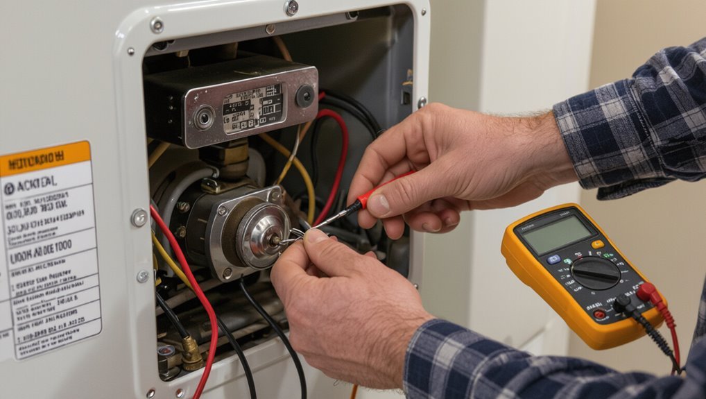
A thermocouple in a water heater senses pilot flame presence and signals the gas valve to stay open.
Common signs of a failing thermocouple include a constantly extinguished pilot, intermittent heating, or difficulty keeping the pilot lit.
Before testing, power and gas should be turned off and basic tools—multimeter, wrench, and safety gloves—should be on hand.
What a thermocouple does in a water heater
Detects and maintains the pilot flame, the thermocouple is a safety sensor that signals the gas valve to stay open only while adequate heat is present.
It converts heat into a small voltage to confirm pilot presence, preventing gas flow if the flame goes out.
Understanding this function is essential when learning how to test thermocouple water heater components and perform safe troubleshooting.
Signs the thermocouple may be failing
With the thermocouple acting as the pilot-flame safeguard, failing behavior usually shows up as specific, observable symptoms.
Common signs include a pilot that won’t stay lit, intermittent extinguishing, delayed ignition, or a heater that stops after a short run.
Reduced hot water consistency and frequent relighting are typical indicators suggesting the thermocouple is weak, dirty, misaligned, or nearing failure.
Safety first required precautions and tools
Safety is paramount before any thermocouple test on a water heater; proper precautions and the right tools prevent injury and equipment damage.
The technician should shut off gas, vent the area, and guarantee pilot is cool.
Essential tools: multimeter, insulated screwdrivers, wrench set, safety goggles, gloves, and a flashlight.
Follow manufacturer guidelines and local codes at all times.
Tools and Materials Needed
To test a thermocouple on a water heater, the technician should gather the right tools and any optional supplies before beginning. Key items include a multimeter, basic hand tools, and safety gear.
- Essential tools: multimeter, wrench, screwdriver, gloves, flashlight
- Optional supplies: replacement thermocouple
- Fuel checks: propane or natural gas supply checklist
Essential tools (multimeter, wrench, screwdriver, gloves, flashlight)
A small set of basic tools is required to test a water heater thermocouple: a multimeter for measuring millivolts, an adjustable wrench to loosen connections, a screwdriver for access panels and mounting screws, protective gloves to prevent burns and cuts, and a flashlight to illuminate the burner compartment.
Each tool should be in good condition and appropriately sized; safety and accuracy depend on proper use and inspection.
Optional supplies (replacement thermocouple, propane or natural gas supply checklist)
Consider keeping a replacement thermocouple on hand and a simple gas supply checklist to streamline repairs and avoid repeat trips during testing.
A spare thermocouple matching the heater model, appropriate fittings, and thread sealant reduce downtime.
The checklist should confirm fuel type (propane or natural gas), valve positions, regulator condition, and available tank or mains pressure.
Store supplies near the heater for quick access.
Preparing the Water Heater for Testing
Before testing begins, the technician guarantees the gas supply and pilot light are turned off and any electrical power to associated components is disconnected.
The work area is ventilated and cleared of flammable materials to minimize risk.
Finally, the thermocouple and its access panel are located so the component can be reached safely.
Turning off gas supply and pilot light
Shut off the gas supply valve and extinguish the pilot light to eliminate any risk of combustion while testing the thermocouple.
Confirm the main gas shutoff is fully closed, then use the water heater’s control knob to turn the pilot to OFF.
Allow a few minutes for any residual gas to dissipate and verify no flame or smell remains before proceeding with testing.
Shutting off electrical power (if electric components present)
Locate and switch off the water heater’s electrical supply at the breaker panel to remove any risk of electric shock before testing the thermocouple.
Confirm power is off using a non-contact voltage tester at the heater’s junction box or controls. Lock or tag the breaker if possible.
Wait for capacitors or components to discharge, then proceed with thermocouple access and inspection.
Ventilation and combustibles clearance
Adequate ventilation and a clear zone around the water heater are essential to safely test the thermocouple and prevent fire or carbon monoxide hazards.
Confirm vents are unobstructed, the area has airflow, and any flammable materials are removed at least three feet from the appliance.
Verify combustion air openings remain open and keep tools and rags clear during testing to avoid ignition risks.
Locating the thermocouple and access panel
Before testing, the thermocouple and its access panel must be identified so the technician can reach the sensor safely and without damaging surrounding components.
Locate the burner assembly and pilot housing near the tank base. Remove the access panel fasteners, keeping screws organized.
Note thermocouple routing to the pilot assembly and any insulation. Confirm clear workspace and adequate lighting before proceeding.
Visual Inspection Before Testing
Before any electrical checks, a visual inspection of the thermocouple and surrounding components identifies obvious issues such as physical damage, corrosion, or sooty buildup.
The pilot assembly and burner should also be examined for misalignment, clogged ports, or signs of incomplete combustion.
If the thermocouple is bent, heavily corroded, or coated in persistent soot, replacement is recommended rather than further testing.
Inspecting thermocouple for damage, corrosion, or soot
A careful visual inspection of the thermocouple provides the quickest indication of whether it requires cleaning or replacement.
The inspector looks for bends, breaks, frayed insulation, greenish corrosion at fittings, dark soot accumulation on the probe, and loose connections at the gas valve.
Any physical damage, heavy corrosion, or thick soot warrants cleaning or replacement before electrical testing.
Checking pilot assembly and burner condition
Inspect the pilot assembly and burner area for signs that could affect thermocouple performance: confirm the pilot flame is steady, blue, and properly centered on the thermocouple tip; note any yellowing, lifting, or fluttering of the flame that indicates incomplete combustion or air flow issues.
Look for clogged pilot orifice, soot buildup, or warped burner components that can divert the flame away from the sensor.
Verify that burner ports are free of obstructions, corrosion, or insect nests that would alter flame shape or stability.
Check mounting screws, fittings, and tube alignment for looseness or mispositioning.
Replace or clean components found contaminated; document findings before proceeding to electrical continuity or millivolt testing.
When to replace instead of test
If the pilot assembly or burner shows severe damage or heavy contamination, replacement of the thermocouple should be chosen over testing.
Corroded, bent, or visibly burned thermocouples, loose fittings, or signs of oil/soot buildup warrant immediate replacement.
When age, intermittent operation, or prior repairs suggest unreliability, replacing the component prevents repeat failures and guarantees safe, consistent pilot operation.
Step-by-Step Thermocouple Testing Procedure
The procedure outlines clear actions to access, test, and restore the thermocouple. Follow these steps in order for safe and accurate results:
- Remove access panel, expose thermocouple, and loosen the mounting nut to detach it.
- Check continuity with a multimeter (ohms) and measure millivolt output at the pilot flame.
- Reinstall the thermocouple and confirm stable pilot operation.
Step 1 Remove access panel and expose thermocouple
Begin by cutting power to the water heater—turn off the gas supply and shut off electrical power at the breaker—to guarantee a safe working environment.
Remove the lower access panel and any insulation to reveal the burner assembly.
Use a flashlight to locate the thermocouple near the pilot light.
Keep small parts organized and note panel fastener positions for accurate reassembly.
Step 2 Inspect and loosen mounting nut; detach thermocouple
Locate the thermocouple connection at the gas valve and visually inspect the mounting nut for corrosion, dirt, or rounded edges that could impede removal.
Use an appropriately sized wrench to break the nut free, turning counterclockwise while stabilizing the thermocouple tube.
Once loosened, gently pull the thermocouple from its pilot assembly, keeping the probe intact and avoiding bending or kinking the tubing.
Step 3 Testing continuity with a multimeter (settings and expected readings)
With the thermocouple removed and the mounting nut loosened, testing continuity with a multimeter verifies whether the sensor still conducts.
Set the meter to low ohms or continuity beep. Connect leads to each thermocouple end (probe tip and connector).
A functioning thermocouple shows low resistance or a beep; infinite resistance or open circuit indicates failure and replacement is needed.
Step 4 Performing voltage output (millivolt) test at pilot flame
Move the pilot flame to a steady, well-centered burn and attach the multimeter set to millivolts across the thermocouple leads to measure its real-time voltage output; this test confirms whether the thermocouple generates the necessary millivolt signal (typically 20–30 mV or more when hot) to keep the gas valve engaged and indicates functional health under operating conditions.
Record stable reading, compare specification.
Step 5 Reinstalling thermocouple and retesting pilot operation
Reinstall the thermocouple by seating it in the pilot assembly and securely fastening its mounting bracket and connector to restore proper alignment and electrical contact.
After reassembly, reopen the gas supply, light the pilot per manufacturer instructions, and observe flame stability and color.
Confirm the pilot remains lit when the control knob is released and verify reliable operation before replacing access panels and restoring normal service.
Step 6 When to test with appliance running vs. cold
When should the thermocouple be tested while the appliance is running versus when it is cold?
The technician tests cold to confirm open-circuit resistance and initial continuity safely. Testing while running verifies millivolt output under operating temperature and pilot flame contact.
Cold checks component integrity; hot confirms real-world response and proper flame sensing.
Follow safety protocols and use insulated leads and a multimeter calibrated for low-millivolt readings.
Interpreting Test Results
The technician compares measured continuity and millivolt values to the manufacturer’s normal ranges to determine whether the thermocouple is operating correctly.
Values considerably below the specified millivolts or an open continuity reading indicate probable failure and warrant replacement.
The reader is also warned that poor connections, dirty fittings, or an improperly positioned probe can produce false positives and should be checked before concluding the unit is bad.
Normal continuity and millivolt ranges
Normal continuity for a functioning thermocouple typically measures as a low-resistance path — often under 1 ohm — while expected millivolt output under pilot flame conditions usually falls between about 20 and 30 mV.
Readings markedly outside these ranges indicate a weak or failed thermocouple that may not reliably hold a gas valve open.
Technicians should compare measured values to these norms, considering measurement tolerance and instrument accuracy.
Readings that indicate failure
Interpret readings as failures when measurements fall clearly outside expected ranges: a steady open-circuit or resistance substantially above 1 ohm, millivolt output under roughly 15–18 mV with a full pilot flame, or erratic/rapidly fluctuating millivolt readings that fail to stabilize.
Such results indicate internal thermocouple degradation, broken wire, poor junction, or contamination.
Replace the thermocouple rather than relying on marginal values for safe operation.
False positives and test troubleshooting
Beware false positives when testing a thermocouple: readings that appear faulty can stem from test technique, equipment limits, or installation issues rather than from the sensor itself.
Verify probe contact, correct multimeter range, and stable junction temperature. Inspect wiring, connectors, and pilot flame position.
Repeat tests after cleaning or reseating components. Confirm results with a known-good thermocouple before replacing parts.
Replacing the Thermocouple
When replacement is necessary, the correct thermocouple must be chosen for type, length, and fittings to guarantee proper fit and function.
The replacement procedure should be followed step by step, including shutting off gas, removing the old unit, and installing the new thermocouple securely.
After installation, the technician verifies connections, relights the pilot according to manufacturer instructions, and checks for proper operation and leaks.
Selecting the correct replacement part (type, length, fittings)
Choosing the correct thermocouple replacement requires matching type, length, and fittings to the water heater’s original specifications and local code requirements.
Confirm the thermocouple type (e.g., K, J) and probe style used by the pilot assembly. Measure overall length from tip to connector.
Verify thread size, compression or flare fittings, and terminal type. Purchase OEM-equivalent or certified compatible parts to guarantee safe operation.
Step-by-step replacement process
Begin by shutting off the gas supply and extinguishing any open flame. Then allow the pilot assembly to cool before proceeding; this guarantees a safe, working environment for the replacement.
Remove access panel, detach thermocouple nut at gas valve, and unclip or unscrew bracket at pilot.
Install matching thermocouple, route similarly, secure fittings hand-tight then snug with wrench.
Restore covers; keep components accessible.
Post-replacement checks and pilot relighting
With the new thermocouple installed and fittings snugged, the technician proceeds to post-replacement checks and pilot relighting to confirm proper operation and leak-free connections.
They inspect joints with soapy water, tighten if bubbles appear, then purge air from gas line per manufacturer instructions.
The pilot is lit, flame stability observed, and the gas control valve cycled to verify the main burner ignites and the system responds correctly.
Common Problems and Diagnostic Scenarios
The following scenarios summarize common thermocouple-related issues and how they present.
- Pilot lights then goes out — distinguish thermocouple failure from a faulty gas valve.
- Weak pilot flame, intermittent failures, or corrosion/contamination can reduce millivolt output or cause poor connections, often traceable to flame adjustment, wiring/connectors, or buildup.
Pilot lights then goes out thermocouple vs. gas valve issues
When a pilot light ignites briefly but then extinguishes, two primary culprits are the thermocouple and the gas valve. Distinguishing between them hinges on observing symptoms and running a few simple tests.
A failing thermocouple usually cools quickly, stopping gas flow. A faulty gas valve can intermittently cut supply despite a good thermocouple.
Measure millivolts and try a known-good thermocouple to isolate the issue.
Weak pilot flame affecting millivolt generation
If a pilot lights but produces a weak flame, attention shifts from component failure to flame quality because inadequate heat on the thermocouple reduces its millivolt output and can mimic a failing sensor or gas valve.
Inspect for clogged orifices, debris, draft, or incorrect air–fuel mix.
Correct cleaning, proper adjustment, or replacing a degraded pilot assembly restores consistent thermocouple heating and millivolt generation.
Intermittent failures and wiring/connectors
Because intermittent thermocouple failures often trace to wiring and connectors, troubleshooting must include a careful inspection of all electrical and mechanical connections between the sensor and the gas valve.
Check for loose terminals, frayed wires, broken insulation, and poor crimp or solder joints.
Wiggle components while observing operation, measure continuity and resistance, and replace damaged connectors or wire segments to restore reliable signal transmission.
Corrosion or contamination causing poor contact
Many thermocouples exhibit degraded performance from corrosion or contamination at junctions and terminals, which impedes the tiny millivolt signal required to keep a gas valve energized.
Technicians should inspect connections, clean corrosion with fine emery cloth or contact cleaner, and verify tight, secure fittings.
Replacing heavily pitted leads or terminal blocks prevents intermittent contact and restores reliable voltage transmission to the gas control.
Safety and Maintenance Tips to Prevent Thermocouple Failure
A concise maintenance regimen can extend thermocouple life: schedule routine inspections, clear soot and debris, and clean connections as needed.
Proper pilot flame height and regular burner servicing help guarantee reliable sensing and prevent premature failure.
Any persistent ignition issues, physical damage, or uncertainty about adjustments should prompt contacting a licensed technician.
Routine inspection schedule and cleaning tips
Regular inspections every six months help catch early signs of thermocouple wear, soot buildup, or loose connections before they cause pilot failures or unsafe conditions.
Inspect for corrosion, frayed wires, and secure fittings.
Gently clean the thermocouple tip with fine emery cloth or steel wool and remove soot from surrounding areas with a soft brush.
Record findings and replace aged components promptly.
Proper pilot flame adjustment and burner maintenance
Check and adjust the pilot flame so it envelops the thermocouple tip with a steady, blue inner cone about 1/4 to 1/2 inch long; a weak, yellow, or flickering flame can fail to heat the thermocouple reliably and should be corrected.
Periodic burner cleaning, removal of soot and debris, checking orifices and air shutters for proper mixture, and tightening connections extend component life and maintain consistent flame characteristics.
When to call a licensed technician
If pilot flame adjustments and burner upkeep do not restore reliable heating or if the flame repeatedly appears weak, yellow, or unstable, it indicates conditions warranting professional evaluation.
A licensed technician should be contacted when gas smells persist, the thermocouple or gas valve shows visible damage, cycling or ignition failures continue after basic checks, or if the homeowner lacks tools, confidence, or legal clearance to perform repairs.
Quick Troubleshooting Flowchart
A concise troubleshooting flowchart helps identify common thermocouple issues by matching symptom to probable cause and action. The table below summarizes symptom, quick test, and recommended action for common failures. Technicians can follow these steps to isolate faults and decide whether repair or replacement is needed.
| Symptom | Quick test | Recommended action |
|---|---|---|
| Pilot won’t stay lit | Check thermocouple voltage or flame contact | Clean/realign or replace thermocouple |
| No pilot light | Confirm gas supply and thermocouple continuity | Restore gas/replace thermocouple |
| Intermittent shutoff | Wiggle thermocouple and observe flame response | Tighten connection or replace thermocouple |
Symptom, probable cause, quick test, recommended action
When a water heater fails to stay lit, the troubleshooting flowchart guides the technician through symptom recognition, probable causes, a fast diagnostic test, and the recommended corrective action in sequence.
Technician notes flame out, weak pilot, or no gas.
Probable causes: dirty thermocouple, misaligned pilot, or faulty gas valve.
Quick test: multimeter millivolt check and pilot reposition.
Recommended action: clean, realign, or replace.
When Testing Is Not Enough: Signs to Replace the Water Heater or Call a Pro
Repeated thermocouple failures can indicate deeper issues such as wiring faults, combustion problems, or a deteriorating pilot assembly that simple testing will not resolve.
Persistent or intermittent gas valve behavior, unexplained burner cycling, or control assembly malfunctions are signs that the problem lies beyond the thermocouple.
In those cases, replacement of major components or consultation with a qualified technician is recommended.
Repeated thermocouple failures and underlying causes
Investigate patterns of thermocouple failure to determine whether the problem is isolated to the sensor or symptomatic of deeper issues with the water heater.
Repeated failures often indicate flame instability, burner sooting, moisture corrosion, loose or damaged wiring, or excessive vibration.
Correlate failure timing with maintenance history and operating conditions; persistent recurrence warrants professional diagnosis and possible replacement of related components or the unit itself.
Gas valve or control assembly symptoms beyond thermocouple scope
Although a faulty thermocouple can cause pilot and ignition issues, failures that persist after sensor testing often point to the gas valve or control assembly.
These components may exhibit symptoms such as intermittent pilot ignition, inability to maintain gas flow, sluggish or unresponsive control knobs, erratic flame behavior, or electronic error codes.
Persistent symptoms, gas smells, or safety lockouts warrant professional diagnosis or replacement to prevent hazards.
Resources and Reference Measurements
The article provides typical millivolt benchmarks for common thermocouple types so readers can compare measured values against expected ranges.
It also points to manufacturer manuals and relevant safety codes for model-specific specifications and compliance guidance.
These resources support accurate testing and informed decisions about repair or replacement.
Typical millivolt benchmarks for common thermocouple types
Benchmarks for thermocouple millivolt output provide quick reference points for diagnosing water heater pilots and gas controls.
Typical Type K yields about 41–55 mV at 300–400°F; Type J about 35–50 mV in similar ranges.
Residential copper-constantan variants often register 20–30 mV under normal pilot heat.
Readings below published ranges indicate weak or failing thermocouples needing further testing or replacement.
Links to manufacturer manuals and safety codes
After comparing measured millivolt outputs to typical ranges, consult manufacturer manuals and applicable safety codes to interpret results and determine proper corrective actions.
Relevant resources include OEM thermocouple specs, appliance installation guides, and local code excerpts.
Recommended links:
- Manufacturer service manual and wiring diagrams.
- National and local gas/electrical safety codes.
- Certified technician troubleshooting and replacement procedures.
Conclusion
In the end, the thermocouple’s quiet duty is like a sentinel at the gate: unseen, yet essential. Following safe testing steps and routine inspection lets one detect its whispers before they become shouts. When readings falter or corrosion appears, replacement or professional help is prudent. Regular maintenance prolongs reliable performance, ensuring warm water flows without drama. By tending this small component, household comfort and safety remain steadfast.