How to Test a Boiler High Water Level Alarm Safely and Step-by-Step
To safely test a boiler high water level alarm, a certified technician must follow a series of steps. First, isolate and lock out the boiler, ensuring all safety protocols are in place. Next, verify documentation and wear appropriate personal protective equipment (PPE). The technician simulates an over-level condition using approved methods or test switches. They then monitor the sensors and control panel responses, confirming that alarms, interlocks, and automatic feedwater shutdowns function correctly. Response times and any faults are logged. If any sensors are found faulty, they should be calibrated, repaired, or replaced, and the tests repeated. Adhering to these procedures ensures compliance and safety. More detailed step-by-step guidance and safety checks are available for thorough verification.
How a Boiler High Water Level Alarm Works
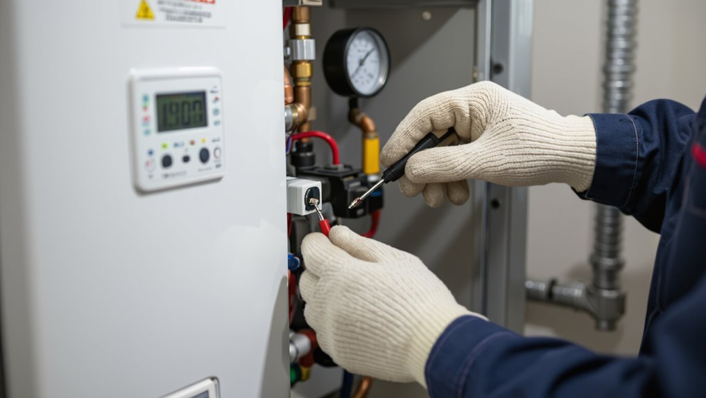
A boiler high water level alarm exists to detect and signal when water rises above safe operating limits, preventing carryover, loss of steam quality, and potential equipment damage.
Common sensing methods include float switches, probe-type electrodes, and ultrasonic or conductive level sensors, each linked to audible/visual alarms or relay outputs.
These alarms interface with boiler controls and safety systems to shut burners, trip pumps, or initiate controlled shutdowns when a high-water condition is confirmed.
Purpose of the high water level alarm
Because steam boilers rely on a precise water-to-steam relationship, the high water level alarm exists to alert operators when water rises above the safe operating range.
Its purpose is to prevent carryover, protect steam lines and equipment, and reduce flooding risk.
Clear indication and reliable activation are essential both for safety and for procedures like how to test boiler high water level alarm during maintenance.
Common types of high water level sensors and alarms
When water level must be monitored precisely, several sensor and alarm technologies are used to detect and signal high-water conditions in steam boilers.
Common types include float switches, electrode probes, conductivity sensors, differential pressure transmitters, and ultrasonic or radar level sensors.
Alarm outputs range from local audible/visual indicators to relay contacts for remote annunciation; each offers different accuracy, maintenance needs, and failure modes.
How the alarm integrates with boiler controls and safety systems
Several interlocked components guarantee a high-water alarm both detects an overfill and triggers protective actions within the boiler control and safety hierarchy.
Sensors feed status to the controller, which logs events and actuates alarms. On verified high-water, the system disables burners, isolates feedwater, starts audible/visual alarms, and sends remote alerts.
Interlocks force manual reset and prevent restart until levels normalize and faults clear.
When and Why You Should Test the High Water Level Alarm
Regulatory standards and manufacturer instructions set baseline requirements for testing the high water level alarm and should guide maintenance schedules.
Immediate testing is warranted when visual or audible signs—such as fluctuating water gauges, persistent feedwater activity, or unexplained alarm events—appear.
Recommended frequencies vary by boiler type and risk level, ranging from daily functional checks on critical systems to monthly or quarterly verifications on lower-risk units.
Regulatory and manufacturer testing requirements
Because high water level alarms are critical to boiler safety, operators must test them according to specific regulatory codes and manufacturer instructions to secure reliable operation.
Regulatory bodies specify test frequency, documentation, and qualified personnel requirements; manufacturers prescribe procedures, test points, acceptable tolerances, and replacement intervals.
Compliance guarantees warranty validity, legal adherence, and predictable alarm performance; records support audits and maintenance planning.
Signs that indicate the alarm needs immediate testing
When should the high water level alarm be tested immediately?
Indicators include unexplained water level fluctuations, recent maintenance or sensor replacement, alarm activation without visible cause, loss of boiler feedwater controls, electrical faults, unusual noises or steam behavior, and after any incident risking float or probe integrity.
Immediate testing prevents overflow, equipment damage, regulatory breaches, and safety hazards.
Recommended testing frequency for different boiler types
Testing frequency for high water level alarms should be tailored to boiler type, service criticality, and operating conditions.
Low-pressure hot water boilers: monthly functional checks and annual full tests.
High-pressure steam boilers: weekly functional checks and quarterly thorough tests.
Industrial or critical-service boilers: daily visual checks, weekly functional tests, and monthly certified inspections.
Adjust frequency after maintenance, repairs, or abnormal events.
Safety Precautions Before Testing the Alarm
Before testing the boiler alarm, appropriate personal protective equipment should be worn and the work area secured to prevent slips, burns, or exposure.
The boiler and related systems must be isolated using lockout‑tagout procedures to guarantee no unintended operation occurs.
All affected personnel should be notified and the test plan documented, including objectives, steps, and contingency actions.
Personal protective equipment and site safety
Personal protective equipment and clear site controls are essential to protect personnel and equipment during boiler alarm testing.
Technicians must wear flame-resistant clothing, safety glasses, gloves, and hearing protection. Hard hats and steel-toe boots are required where overhead or impact hazards exist.
Establish exclusion zones, post warning signs, maintain good lighting, and guarantee unobstructed emergency exits to minimize risk and enable rapid response.
Lockout-tagout and isolating boiler systems
With personnel and site controls in place, attention shifts to isolating energy sources and implementing lockout-tagout (LOTO) procedures to prevent accidental boiler startup or release of hazardous energy.
Authorized technicians identify and isolate feedwater, fuel, steam, and electrical supplies, apply locks and tags, verify zero energy with testing, and secure mechanical isolation points.
Only authorized personnel remove LOTO after safe restoration.
Notifying personnel and documenting the test plan
Notify affected staff and document a clear test plan that specifies objectives, schedule, roles, communication methods, expected alarm behaviors, and contingency actions.
The plan should list authorized testers, emergency contacts, isolation procedures, and required permits. Distribute copies to operators, maintenance, and supervision.
Confirm acknowledgments, establish watch personnel during tests, and record results, anomalies, corrective actions, and signatures for traceability and compliance.
Tools and Materials Needed for Testing
Before beginning tests, the technician gathers all necessary tools and reference materials to guarantee an efficient and accurate procedure.
Essential items include:
- Diagnostic tools and instruments
- Replacement parts and test equipment
- Documentation and manufacturer manuals
Having these on hand reduces downtime and supports correct troubleshooting.
Required diagnostic tools and instruments
To accurately assess a boiler alarm system, a set of specific diagnostic tools and materials is essential; these items enable safe, consistent, and verifiable tests of sensors, circuits, and control logic.
Required instruments include a multimeter (voltage, continuity), clamp ammeter, insulation tester, calibrated pressure/temperature gauges, portable oscilloscope or data logger for signal tracing, and noncontact voltage detector for safe live checks.
Replacement parts and test equipment
With the diagnostic instruments established, attention turns to the replacement parts and specific test equipment that technicians will need on hand for effective boiler alarm troubleshooting.
Stock common level probes, float switches, relays, fuses, and wiring terminals.
Carry a multifunction tester, calibrated pressure/temperature gauges, insulated hand tools, replacement alarm modules, spare connectors, and sealant.
Confirm spare batteries and labeled cable ties.
Documentation and manufacturer manuals to have on hand
Although often overlooked, thorough documentation and manufacturer manuals are essential tools during boiler alarm testing. They provide calibrated procedures, wiring diagrams, error-code tables, and maintenance histories that secure accurate diagnosis and safe repairs.
Technicians should keep the boiler’s installation manual, control panel schematics, sensor specifications, wiring color codes, past inspection records, and firmware update notes to validate correct testing, troubleshooting, and compliance.
Step-by-Step Procedure to Test a Boiler High Water Level Alarm
The technician begins by preparing the boiler and test area, ensuring isolation, permits, and safety measures are in place.
Baseline operating conditions and readings are recorded before a controlled simulation of a high water condition is performed to trigger the alarm.
Responses are observed and documented, including alarm activation, control actions, audibility, visual indicators, and any remote signals.
Step 1 Prepare the boiler and test area
Begin by securing the boiler room and isolating the unit so technicians can work safely and access all required components.
Confirm lockout/tagout, ventilate the space, and post warning signs.
Gather personal protective equipment, tools, and testing instruments.
Guarantee lighting and clearance around gauges, probes, and the sight glass.
Verify emergency exits and extinguisher accessibility before proceeding.
Step 2 Verify normal operating conditions and baseline readings
With the boiler secured and the workspace prepared, technicians confirm that the unit is operating under normal load and pressure before recording baseline readings for the high water level alarm test.
They document water level, steam pressure, feedwater valve position, and control-panel indications.
Instrumentation is calibrated and functioning. Any anomalies are noted and corrected prior to proceeding to controlled alarm testing.
Step 3 Simulate high water condition safely (manual/controlled methods)
To simulate a high-water condition, technicians methodically raise the boiler water level using approved manual or controlled means—such as incrementally opening the feedwater valve, activating the feedwater pump in short bursts, or employing a calibrated test tank—while continuously monitoring level indicators and safety interlocks.
All adjustments are made slowly, within predetermined limits, and under lockout/tagout and communications protocols to prevent inadvertent overfill or steam carryover.
Technicians log setpoints, confirm redundancy of sensors, coordinate with operations, and halt testing immediately if abnormal pressure, foaming, or control anomalies occur.
Step 4 Observe alarm activation and control responses
Technicians monitor the boiler and control panel closely as the water level reaches the alarm setpoint, noting the exact moment the high-water alarm annunciates, any associated visual or audible warnings, and the automatic control actions such as feedwater cutoff, burner lockout, or diversion of steam drains.
They document response timings, verify interlocks actuate, confirm annunciator status changes, and record any abnormal behavior for corrective action.
Step 5 Test alarm audibility, visual indicators, and remote signals
After confirming alarm actuation and recording control responses, attention shifts to verifying the alarm’s audibility, visual indicators, and any remote signals to guarantee operators and monitoring systems receive clear notification.
Test sirens and speakers at normal and reduced hearing distances, confirm beacon lamps and panel LEDs illuminate correctly, and validate telemetry/SCADA alerts reach remote consoles.
Log outcomes and note any deficiencies for correction.
Step 6 Reset the alarm and restore normal operation
Begin by confirming the boiler is stable and all personnel and processes are clear of alarm conditions before initiating the reset sequence.
The operator isolates test inputs, verifies water level is within safe range, and follows manufacturer reset procedure to silence and clear the alarm.
Restore normal control settings, re-enable interlocks and remote outputs, then monitor indicators to guarantee automatic operation resumes correctly.
Step 7 Repeat test after any adjustments or repairs
Confirm that the system is returned to normal operating condition before repeating the high-water-level alarm test following any adjustments or repairs.
Verify repairs are complete, restore power and water supply, and clear fault indicators.
Re-run the prescribed test procedure, observe alarm activation and shutdown actions, record results, and confirm alarm resets properly.
If failures persist, escalate to qualified maintenance and document corrective actions taken.
How to Test Specific Sensor Types
The procedure varies by sensor type and requires tailored checks for reliable alarm operation.
Tests should cover float switches and mechanical probes, conductivity and optical level sensors, pressure-based and differential level devices, and electronic transmitters with control-panel integration.
Each category demands specific test inputs, expected responses, and verification of wiring and signal interpretation.
Testing float switches and mechanical probes
Inspecting float switches and mechanical probes requires gentle handling and systematic checks to verify movement, continuity, and proper mounting.
The inspector manually actuates floats, observes free travel, and checks for corrosion or obstructions. Use a multimeter to confirm open/closed states during movement.
Verify probe alignment, secure fastenings, and watertight seals. Record findings and replace worn components before retesting the alarm.
Testing conductivity/optical level sensors
After checking float switches and mechanical probes, attention shifts to conductivity and optical level sensors, which operate on different principles and consequently require different test methods.
For conductivity sensors, isolate power, apply calibrated conductivity solution or jumper terminals to simulate-liquid continuity, and verify alarm activation.
For optical sensors, clean optics, use a non-conductive test block or remove liquid to confirm beam interruption, then restore normal conditions.
Testing pressure-based and differential level devices
Move on to pressure-based and differential level devices by verifying sensor integrity, line condition, and calibration before any live testing.
Inspect impulse lines for blockages or leaks, purge and reconnect as needed.
Apply known pressure or use a calibrated hand pump to simulate water head, confirm differential transducer response against reference, and record setpoints and hysteresis for alarm verification.
Testing electronic transmitters and control-panel integration
Begin by confirming transmitter wiring, grounding, and power supplies are correct and stable.
Then verify that device configuration matches the control-panel addressing and expected signal ranges.
Calibrate the transmitter using known reference levels or loop calibrator; observe analog/current or digital outputs for linearity.
Test alarm thresholds, fault reporting, and polling updates.
Document results, restore normal modes, and tag any discrepancies for corrective action.
Interpreting Test Results and Troubleshooting
The technician compares activation patterns and conditions to distinguish normal alarm responses from false trips.
Common failure modes — such as sensor drift, wiring faults, or power issues — are identified through targeted diagnostic checks.
Repair steps then follow a clear progression: recalibrate sensors where possible, replace defective components, and retest the system to confirm proper operation.
Normal activation vs. false alarms
A clear distinction between normal activation and false alarms is essential when interpreting boiler alarm test results, because proper classification directs the next steps in troubleshooting and maintenance.
Normal activation aligns with documented test stimuli, system responses, and timing. False alarms show inconsistent triggers, no correlated water-level evidence, or intermittent signaling.
Record observations, isolate variables, and repeat tests to confirm classification before corrective action.
Common failure modes and diagnostic checks
Identify likely failure modes—such as sensor drift, stuck float mechanisms, wiring faults, relay/contact wear, and controller logic errors—and pair each with specific diagnostic checks that isolate cause:
- verify sensor accuracy with a calibrated instrument,
- inspect float movement and linkage for corrosion or obstruction,
- perform continuity and insulation tests on wiring and connectors,
- exercise relays under load and inspect contacts, and
- review controller settings and event logs for anomalous logic or timing.
Follow-up testing should confirm repeatability.
Steps to repair, recalibrate, or replace faulty components
Following diagnostic checks that isolate likely failure modes, technicians should interpret test results methodically to determine whether repair, recalibration, or replacement is warranted.
Document readings, compare against manufacturer tolerances, and prioritize safety-critical parts.
Perform targeted repairs or bench recalibration, then retest.
If drift, corrosion, or mechanical damage persists, replace the component with OEM-equivalent parts, verify system integration, and record outcomes for maintenance logs.
Documentation and Compliance Reporting
The procedure and outcomes of each boiler alarm test should be recorded clearly, including date, time, alarm type, measured response times, observed faults, corrective actions, and post-test status.
Sample log entries should show required fields, signatures of the technician and supervisor, and any verifier initials to establish chain of custody.
These records must meet applicable regulatory and insurance documentation standards to support compliance and future audits.
What to record during and after the test
When conducting a boiler alarm test, accurate documentation guarantees traceability, compliance, and effective follow-up; records should capture both test inputs and observed outcomes.
Record test date, time, personnel, equipment IDs, pre-test conditions, simulated trigger method, alarm activation time, response actions, sensor readings, anomalies, corrective actions taken, and post-test status.
Note reference standards and any required follow-up inspections.
Sample test log items and signatures
Include a concise set of standardized log items and designated signature blocks to guarantee each test is auditable and accountable.
Recommended entries: date, time, tester name and role, equipment ID, test type, pre-test condition, steps performed, observations, measured values, discrepancies, corrective actions, parts replaced, retest results.
Provide signature, printed name, and date for tester and supervisor to validate completion.
Meeting regulatory and insurance documentation requirements
Compliance requires systematic documentation that aligns with regulatory standards and insurance policies, ensuring boiler alarm tests are verifiable and defensible.
Records should include test dates, personnel, procedures, instrument calibration, results, corrective actions, and signatures.
Retention periods must meet jurisdictional and insurer mandates.
Reports should be auditable, accessible, and incorporated into maintenance programs to demonstrate due diligence and support claims or inspections.
Preventive Maintenance to Reduce Alarm Failures
Preventive maintenance focuses on routine inspections of level sensors and associated piping to detect wear, blockage, or corrosion before they cause alarm failures.
It includes scheduled cleaning, calibration, and component replacement based on manufacturer intervals and operating conditions.
Staff training and a formal testing schedule guarantee consistent execution and timely recordkeeping.
Routine inspection checklist for level sensors and piping
When preparing a routine inspection checklist for level sensors and associated piping, technicians should verify sensor mounting, wiring integrity, and signal continuity.
They should also examine piping for leaks, corrosion, and proper drainage. This focused review helps identify wear, installation faults, or process changes that commonly lead to false or missed boiler alarms.
Include sensor alignment, conduit seals, junction box condition, mechanical supports, and valve positions.
Cleaning, calibration, and replacement intervals
Establishing a clear schedule for cleaning, calibration, and part replacement considerably reduces false alarms and missed trips by maintaining sensor accuracy and reliable signal integrity.
Technicians should document procedures, tolerances, and acceptance criteria so tasks are repeatable and auditable.
Periodic cleaning removes deposits from probes and traps, calibration verifies setpoints against standards, and timed replacement of sensors, seals, and wiring prevents age-related failures.
Training staff and establishing a testing schedule
Building on a documented maintenance regime for cleaning, calibration, and timed replacement, staff competence and a formal testing cadence guarantee those procedures deliver reliable alarm performance.
Personnel receive role-specific training, competency checks, and recordable assessments. A written testing schedule—daily inspections, monthly functional tests, quarterly calibration verification, and annual audits—ensures timely detection of degradation.
Responsibilities, escalation paths, and documentation templates are standardized.
Safety and Liability Considerations
The author notes that qualified technicians or certified inspectors should be contacted for complex faults, code compliance checks, or whenever safety is uncertain.
They also emphasize that improper testing can have legal and insurance consequences if it voids warranties, breaches regulations, or contributes to damages.
Finally, clear emergency steps—shutting down the boiler, isolating fuel and power, evacuating if needed, and contacting emergency services—are recommended if an alarm fails during operation.
When to call a licensed technician or boiler inspector
When should a licensed technician or boiler inspector be contacted after an alarm activates?
Contact is advised immediately if alarms recur, water level controls fail to reset, visible leaks, corrosion, or steam/water discharge occur, or if the operator is unsure about diagnostics.
Also call a licensed professional when safety interlocks are bypassed, testing reveals inconsistent readings, or documentation indicates prior unresolved issues requiring formal inspection.
Legal and insurance implications of improper testing
If improper testing leads to a false sense of safety or missed faults, liability can extend to the person or organization that performed the test, potentially triggering regulatory penalties, civil claims, or denial of insurance coverage.
Documented procedures, qualified personnel, and adherence to manufacturer and code requirements reduce exposure. Insurers may reject claims if testing deviated from standards or lacked proper records, increasing financial and legal risk.
Emergency actions if the alarm fails during operation
Given the liability risks tied to improper testing, operators must also plan for scenarios where an alarm fails during operation.
Procedures should mandate immediate boiler shutdown, isolation of fuel and feedwater sources, and manual level verification by qualified personnel.
Notifications to supervisors, facility safety officers, and external emergency services must follow predefined protocols.
Document actions, preserve evidence, and suspend operations until repairs and verification are completed.
Comparison of Common Testing Methods
Compare the common testing methods by examining their accuracy, required tools, time investment, and safety implications. The detached overview contrasts visual inspection, float switch simulation, electrical continuity tests, and full-system trip tests, noting precision, technician skill, downtime, and hazard controls to guide method selection.
| Method | Key trade-off |
|---|---|
| Visual inspection | Low tools, low accuracy |
| Float simulation | Moderate tools, moderate safety |
| Continuity test | Quick, requires electrical skill |
| Full trip test | Most accurate, highest downtime |
Conclusion
Regular testing of boiler high water level alarms is essential: studies show over 40% of boiler incidents link to water-level failures, underscoring the risk. A concise, documented testing routine—paired with proper PPE, isolation procedures, and calibrated instruments—reduces false trips and prevents hazardous overfills. Routine maintenance, clear reporting, and adherence to manufacturer and code requirements protect personnel and property while demonstrating due diligence and minimizing regulatory and liability exposure.