How to Size a Vacuum Pump: Step-by-Step Guide to Choose the Right Pump for Your Application
To effectively size a vacuum pump, you need to consider the ultimate pressure, steady-state gas load, and pumping speed, while also factoring in conductance losses, vapor loads, duty cycle, and safety margins. Start by determining the required pressure and gas throughput. Use the formula for pumping speed (S = Q/P) and adjust for piping conductance, ensuring to leave room for variability. Select a pump type suitable for the specific gases and vapors in your application, confirming its duty cycle and material compatibility. Lastly, evaluate lifecycle costs for a comprehensive decision. For detailed calculations, examples, and commissioning tips, continue reading.
How to Choose the Right Vacuum Pump for Your Application Key Considerations
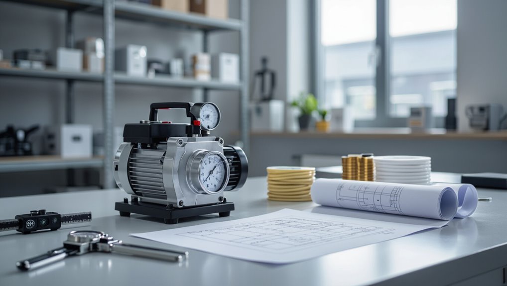
Selecting the right vacuum pump begins with understanding sizing: the required ultimate pressure and flow rate determine pump type and capacity.
Industries such as semiconductor manufacturing, food packaging, medical devices, and chemical processing frequently perform precise pump sizing to meet process demands.
Matching pump performance to application conditions—including gas composition, temperature, and duty cycle—ensures reliable operation and efficiency.
Quick summary of what sizing a vacuum pump means
Choosing an appropriately sized vacuum pump means matching the pump’s ultimate pressure, pumping speed (flow rate), and duty capability to the process requirements—ensuring it can reach the necessary vacuum level, maintain that level under expected gas loads, and run reliably for the planned cycle times.
A concise summary of how to size a vacuum pump: quantify required pressure, calculate gas load and flow, include margins, and verify duty/compatibility.
Common industries and applications that require vacuum pump sizing
After defining required pressure, gas load, and duty factors, attention turns to the industries and applications that commonly demand careful vacuum pump sizing.
Semiconductor manufacturing, laboratory research, freeze-drying, vacuum coating, medical devices, and food packaging require precise flow and ultimate pressure control.
Chemical processing, petrochemical degassing, and HVAC leak detection also need tailored pumps to handle specific gas compositions, temperatures, and continuous duty cycles.
Essential Vacuum Pump Basics You Need to Know
A clear grasp of pump categories—such as rotary vane, diaphragm, dry scroll, and diffusion—and their operational differences is fundamental to selecting the right unit.
Equally important are core performance terms (ultimate and working pressure, flow in CFM or m3/h, and vacuum units like torr and microns) that describe what a pump can achieve.
Finally, interpreting pump curves and performance charts links those specifications to real-world conditions, showing how flow and pressure change under load.
Types of vacuum pumps and how they differ
Because different applications demand distinct pressure ranges, flow rates, and contamination controls, the selection of a vacuum pump begins with understanding the main pump types—positive displacement, momentum transfer (molecular), and entrapment—and how their operating principles, ultimate vacuum, maintenance needs, and tolerance to vapors or particulates set them apart.
- Positive displacement: high flow, moderate vacuum, robust to particulates.
- Momentum transfer: deep vacuum, sensitive to vapors.
- Entrapment: cryogenic/chemical trapping for ultra-clean, low maintenance.
Key vacuum performance terms: ultimate pressure, working pressure, CFM, m3/h, torr, microns
Clear definitions of vacuum performance terms are essential for matching pump capabilities to application requirements.
Ultimate pressure denotes the lowest achievable absolute pressure; working pressure is the normal operational range.
CFM (cubic feet per minute) and m3/h quantify volumetric flow.
Torr and microns (micrometers of mercury) express pressure on fine-vacuum scales.
Proper unit comprehension prevents specification mismatches and guarantees system performance.
How pump curves and performance charts work
Understanding unit definitions sets the stage for interpreting pump curves and performance charts, which translate those terms into actionable data.
The charts plot flow versus pressure, showing capacity, ultimate pressure, and efficiency across operating ranges. Read curves to match required throughput at target pressure, note overlapping startup and stall zones, and apply safety margins.
Manufacturer notes clarify testing conditions and corrections.
Step 1 Define Your Process Requirements
The first step is to specify the process vacuum targets and operating pressures so pump selection matches required ultimate and working levels.
Next, quantify gas load and throughput from leaks, desorption, and any purge flows, and define the gas composition including condensable versus non-condensable species.
Finally, establish duty cycle, required run-time, and redundancy or backup needs to guarantee reliable operation under expected conditions.
Determine required ultimate and operating pressures
Determine the ultimate and operating pressures required for a process by specifying the lowest pressure the system must reach (ultimate pressure) and the pressure range in which it must reliably operate during normal cycles (operating pressure).
Record required pressure tolerances, stability, and transient excursions. Match pump technology and materials to achievable ultimate pressure.
Specify measurement points and control setpoints to guarantee repeatable performance.
Calculate required gas load and throughput (leakage, desorption, purge flow)
Calculate the total gas load by summing steady and transient contributions—external leakage, desorption from internal surfaces and materials, process purge and feed flows, and any intentional venting—expressed in standard units (mbar·L/s or Pa·m^3/s).
Quantify leak rates, estimate outgassing rates (including temperature and surface area effects), and add operational purge or feed flows.
Include safety margins and duty-cycle weighting for transient events.
Identify gas composition and vapor loads (condensable vs non-condensable)
Because gas behavior dictates pump selection and downstream handling, identifying the process gas composition and the fraction that is condensable versus non‑condensable is essential before sizing a vacuum pump.
Determine molecular species, partial pressures, and vapor pressures of condensables at operating temperature.
Quantify vapor load to select traps, condensers, or dry pumps, and assess materials compatibility and corrosion or condensation risks.
Establish duty cycle, run-time, and redundancy needs
Establishing the duty cycle, expected run-time, and redundancy requirements defines how the vacuum system will be used and directly influences pump size, control strategy, and maintenance planning.
Determine continuous versus intermittent operation, average and peak daily hours, and seasonal variations.
Specify required uptime, acceptable repair windows, and spare or parallel pumps for failover.
These choices set cooling, lubrication, and service schedules.
Step 2 Calculate Required Pumping Speed and Capacity
The next step converts process flow units (CFM ↔ m3/h) so all inputs share consistent units and then applies the pumping speed formula S = Q/P (with Q at operating pressure) to compute the required pump capacity.
A worked example should show unit conversion, insertion of Q and operating pressure into the formula, and the resulting S value.
Finally, the raw S is adjusted for system conductance and piping losses to specify the practical pump speed needed at the vacuum flange.
How to convert process flow units (CFM ↔ m3/h)
Converting between cubic feet per minute (CFM) and cubic meters per hour (m3/h) is a straightforward but essential step in matching process flow requirements to pump specifications. Use direct conversion factors: 1 CFM ≈ 1.699 m3/h and 1 m3/h ≈ 0.589 CFM. Convert measured flows to the units used on pump curves before selecting capacity.
| Input | Factor | Result |
|---|---|---|
| 1 CFM | ×1.699 | 1.699 m3/h |
| 10 CFM | ×1.699 | 16.99 m3/h |
| 1 m3/h | ×0.589 | 0.589 CFM |
| 20 m3/h | ×0.589 | 11.78 CFM |
Formula and worked example for required pumping speed at operating pressure
Step 2 defines the pumping speed required at the process operating pressure by relating the gas throughput (often in m3/h or CFM) to the target ultimate pressure using the formula S = Q / P, where S is pumping speed (volume/time), Q is gas load (pressure·volume/time, e.g., mbar·L/s or Torr·L/s), and P is the operating pressure (same pressure units as in Q).
Example: Q = 100 mbar·L/s, P = 0.1 mbar → S = 1000 L/s.
Adjusting for system conductance and piping losses
Because piping, valves, and fittings restrict flow, the ideal pumping speed calculated from Q/P must be increased to compensate for conductance losses between the process and the pump.
The designer estimates line conductance using geometry and flow regime, converts to equivalent pumping speed reduction, and applies a safety margin.
Iteratively adjust pump selection until corrected speed meets target throughput at operating pressure.
Step 3 Select Pump Type and Configuration
The selection process begins by matching pump technology to the gas and vapor characteristics—options include dry, oil-sealed, rotary, roots, and turbomolecular designs.
Consider whether a single-stage unit suffices or a multi-stage arrangement with an appropriate backing pump is required to cover the full pressure range.
Where capacity or ultimate pressure demands exceed a single machine, combinations or boosters are chosen to extend performance and optimize efficiency.
Matching pump technology to gas/vapor type (dry, oil-sealed, rotary, roots, turbomolecular)
When selecting pump technology, matching the machine to the gas or vapor composition is critical because different designs tolerate particulates, condensable vapors, corrosives, and reactive gases to varying degrees.
Dry pumps resist contamination and offer low maintenance; oil-sealed pumps handle leaks and provide better sealing for some vapors.
Roots boosters increase throughput at higher pressures; turbomolecular pumps suit clean, high-vacuum, non-condensing gases.
Single-stage vs multi-stage setups and backing pumps
After choosing pump technology based on gas and vapor characteristics, attention turns to whether a single-stage unit suffices or a multi-stage arrangement with backing pumps is required.
Single-stage pumps handle modest flow and moderate ultimate vacuum.
Multi-stage systems combine roughing and high-vacuum stages to reach lower pressures and higher throughput; backing pumps manage exhaust from high-vacuum machines and protect them from overload.
When to use pump combinations or boosters
If application demands exceed a single pump’s capacity, combining technologies or adding boosters optimizes throughput and lower-end pressure without overtaxing individual units.
Use combinations when duty cycle, ultimate pressure, or gas load exceed one pump’s reliable range.
Common pairings: roughing pump plus roots or booster for high flow at medium vacuum, and cascade stages for deeper vacuum with manageable compression ratios.
Step 4 Sizing for Real-World Factors and Safety Margins
Step 4 addresses practical adjustments to calculated pump capacity, including applying safety factors and recommended headroom to accommodate process variability.
It also considers environmental influences such as temperature, ambient conditions, and altitude that affect pump performance.
Finally, material compatibility and required certifications for corrosive, explosive, or otherwise hazardous gases are reviewed to guarantee safe, compliant operation.
Applying safety factors and headroom recommendations
When translating calculated duty into a practical pump selection, designers must add safety factors and operational headroom to account for measurement uncertainty, process variability, and unforeseen loads.
Typical recommendations specify 10–30% capacity margin depending on criticality.
Consider transient spikes, fouling, seal leakage, maintenance degradation, and part tolerances.
Document chosen margins and validate with field testing to confirm reliable margin adequacy.
Temperature, ambient conditions, and altitude effects
Ambient temperature, site climate, and altitude materially alter vacuum pump performance and must be included in final sizing calculations.
Reduced air density at high altitude lowers cooling capacity and motor output; cold or hot ambient temperatures change lubricant viscosity, sealing, and vapor pressure.
Adjust required flow and power margins, specify altitude and temperature ratings, and validate cooling and duty cycle to guarantee reliable real-world operation.
Corrosive, explosive, or hazardous gases material and certification considerations
Safety and chemical compatibility are primary determinants in selecting and sizing vacuum pumps for processes involving corrosive, explosive, or otherwise hazardous gases.
Material selection, seals, and coatings must resist corrosion and prevent reactions.
Explosion-proof or intrinsically safe motors, ventilation, and purge systems are required for flammable atmospheres.
Compliance with ATEX, IECEx, NFPA, and local regulations, plus certified testing and documentation, guarantees safe, compliant operation.
Integration Considerations: System Layout and Controls
Integration requires attention to piping, valves, traps, and filters to protect pump performance and prevent contamination.
Strategic placement of vacuum gauges and a clear control strategy guarantee accurate monitoring and stable operation.
Provision for maintenance access, defined service intervals, and spare-parts planning reduces downtime and extends system life.
Piping, valves, traps, and filters to preserve performance
Careful selection and layout of piping, valves, traps, filters directly influence a vacuum system’s achieved pressure, throughput, and maintenance intervals.
Specify low-leak fittings, minimize length and bends, and size diameters to maintain conductance.
Install isolation valves for service, condensation and particle traps upstream of the pump, and appropriate filters to protect internals.
Arrange access points for routine inspection and replacement.
Placement of vacuum gauge(s) and control strategy
After sizing and routing the piping and selecting valves, traps, and filters, attention shifts to where and how vacuum gauges are placed and how the system will be controlled.
Gauges should be located near process points, pump inlet, and downstream of critical components for accurate monitoring.
Control strategy defines setpoints, sequencing, interlocks, and feedback loops, balancing response speed, stability, and protection against overpressure or contamination.
Maintenance access, service intervals, and spare parts planning
When planning maintenance access, service intervals, and spare parts inventories, the system layout and control architecture must be arranged so technicians can reach pumps, valves, filters, and gauges without disassembling adjacent equipment or interrupting critical processes.
Define preventative schedules based on duty cycle and contaminant load, stock critical wear parts, document service procedures, and provide isolation points and lockout tags.
Remote diagnostics reduce downtime.
Cost, Energy, and Lifecycle Trade-offs
Selecting a vacuum pump requires balancing upfront capital cost against ongoing operating expenses such as energy consumption and consumables.
Different pump technologies and the use of variable speed drives can materially affect efficiency and annual energy use.
A simple total cost of ownership comparison, with example calculations for purchase price, kilowatt-hours, maintenance, and expected service life, clarifies which option is least costly over time.
Comparing capital cost vs operating cost (energy, consumables)
A clear evaluation of capital cost versus operating cost is essential because upfront savings on a smaller or cheaper vacuum pump can be outweighed by higher energy consumption, more frequent maintenance, and consumable replacement over the equipment’s life.
Total cost of ownership should include energy use, spare parts, filter and oil changes, downtime risk, and expected service intervals to inform an optimized purchase decision.
Efficiency differences across pump types and variable speed drives
Having weighed capital versus ongoing expenses, attention turns to how inherent efficiency differences among pump technologies and the use of variable speed drives (VSDs) affect total cost of ownership.
Rotary vane, dry claw, roots, and liquid ring pumps exhibit varied efficiency across pressure and load.
VSDs reduce energy at partial loads, smooth cycles, and extend component life, though they add upfront cost and control complexity.
Estimating total cost of ownership with examples
Cost assessment combines upfront equipment price, projected energy consumption, maintenance and repair expenses, and expected service life to yield a realistic total cost of ownership (TCO). Example calculations compare a low-capex, high-energy pump versus higher-capex, efficient models; include downtime risk and consumables. Decision uses net present value of operating costs to select the lowest lifecycle expense.
| Factor | Example |
|---|---|
| Capex | $5,000 vs $9,000 |
| Energy/year | $3,200 vs $1,800 |
| Maintenance/year | $800 vs $400 |
| Service life | 5 years vs 10 years |
Common Sizing Mistakes and How to Avoid Them
Common sizing mistakes often stem from underestimating vapor loads and failing to account for backstreaming, which can overwhelm pump capacity and contaminate the system.
Neglecting conductance losses and placing gauges improperly leads to inaccurate performance assessments and undersized selections.
Additionally, overlooking transient loads and pump warm-up behavior results in poor response during startup and process upsets.
Underestimating vapor loads and backstreaming issues
Many systems encounter performance shortfalls when vapor loads and oil backstreaming are underestimated, because these factors directly affect achievable vacuum level, pump selection, and contamination control.
Designers should quantify vapor pressure, condensable fraction, and expected throughput.
Specify traps, cold traps, or chemical scrubbers and choose pumps tolerant of vapors or with appropriate seals.
Regular maintenance and vapor management prevent contamination and capacity loss.
Ignoring conductance losses and incorrect gauge placement
Underestimating vapor loads can be compounded by poor system layout and improper instrument placement, which together undermine achievable pumping speed and accurate pressure readings.
Conductance losses in narrow tubing, long runs, and restrictive fittings reduce effective throughput; gauges located near pumps instead of process points misrepresent process pressure.
Properly sizing lines, minimizing bends, and placing gauges at the application provide realistic performance and prevent undersized pump selection.
Overlooking transient loads and pump warm-up behavior
Although steady-state loads often drive initial pump selection, transient loads and warm-up behavior can dictate real-world performance and reliability.
Transient spikes, gas bursts, and cold-start inefficiencies may exceed nominal capacity, causing prolonged recovery, increased wear, or process upset.
Proper sizing must include headroom for peak flows, staged control strategies, and documented warm-up procedures to guarantee consistent vacuum levels and equipment longevity.
Practical Worked Examples and Scenarios
The section presents three concise worked examples to illustrate sizing principles in different contexts.
Example A covers a laboratory freeze dryer and its low-flow, high-vacuum requirements.
Examples B and C address an industrial vacuum packaging line and a semiconductor process combining a turbopump with a roughing stage.
Example A Laboratory freeze dryer sizing
Example A examines a small laboratory freeze dryer used for research-scale lyophilization of aqueous samples, specifying chamber volume, typical condensate load per run, and desired cycle times to calculate required pump capacity and ultimate vacuum level.
The worked scenario then steps through selection of primary and backing pumps, checks for vapor compression limits, and includes safety margins for repeatability and occasional heavier loads.
Calculations yield pump speeds, condensation capacity, and control recommendations.
Example B Industrial vacuum packaging line
For an industrial vacuum packaging line, this worked example translates production throughput, package volume, and target cycle time into specific pump and system requirements:
Calculate required evacuation flow by dividing package internal volume by cycle time, include leak and permeation margins, and add parallel pumps for redundancy.
Specify target ultimate pressure, choose compatible pump type (dry or oil-sealed), and size piping and valves to minimize conductance losses.
Example C Semiconductor process with turbopump and roughing stage
A semiconductor processing line combining a turbomolecular pump with a mechanical roughing stage requires coordinated selection and sizing to meet both high-vacuum ultimate pressure and practical pumpdown time constraints.
The engineer calculates chamber volume, target base pressure (10^-6 to 10^-7 Torr), and acceptable pumpdown time.
Choose a roughing pump for throughput to 10^-3 Torr and a turbopump with appropriate compression and backing capacity, including valves and foreline sizing.
Verification, Testing, and Commissioning Checklist
The commissioning phase begins with defined pre-start tests and clear performance validation steps to confirm the pump meets design assumptions.
Technicians compare measured data to pump curves to verify flow, ultimate pressure, and operating points during commissioning.
Finally, a set of ongoing monitoring metrics—such as throughput, power draw, and pressure stability—is established to guarantee continued correct sizing and early detection of deviations.
Pre-start tests and performance validation steps
Several essential pre-start tests and validation steps guarantee a vacuum pump and its system will operate safely and meet performance requirements before commissioning.
Inspect mechanical integrity, verify electrical connections, and confirm control logic.
Execute functional checks: leak tests, oil/fluids level, and vibration baseline.
Record baseline performance metrics and safety interlocks.
- Leak and vacuum hold tests
- Electrical and control verification
- Baseline performance logging
How to interpret pump curves during commissioning
How should measured operating points be read against the manufacturer’s pump curve to confirm acceptable performance during commissioning?
Commissioning compares measured flow and ultimate pressure to the curve, verifying operation within rated regions. Deviations indicate leaks, blockages, or incorrect speed.
Confirm margin for process variations, guarantee measured points fall on or above required curve for capacity, and document results for warranty and troubleshooting.
Ongoing monitoring metrics to ensure correct sizing
Following confirmation that measured operating points align with the manufacturer’s pump curve, ongoing monitoring metrics provide a continuous check that the installed pump maintains correct sizing under real-world conditions.
Key metrics include sustained inlet pressure, achieved flow rate, power draw, temperature, vibration, oil contamination and leakage rates.
Trend analysis, alarm thresholds, periodic performance tests and log comparisons to baseline commissioning data validate continued suitability.
When to Consult a Specialist and What Information to Provide
When project complexity, unusual process conditions, or tight performance margins arise, a specialist should be engaged early.
The team should prepare clear data and drawings — process flow, pressures, temperatures, gas composition, required ultimate vacuum, and piping/layout schematics — to share with vendors.
Key questions for manufacturers and integrators include expected pump-down times, compatibility with process gases, maintenance intervals, control/interface options, and warranty/service support.
Data and drawings to prepare for vendor support
Before engaging a vendor, the engineer should assemble a concise package of process data and drawings that enable accurate pump selection and quote generation.
Provide clear, targeted information to accelerate assessment and reduce iterations.
- Process flow diagram, operating pressures/temperatures, gas composition and contaminant levels
- Required ultimate pressure, throughput (sccm/Pa·m3/s), duty cycle
- Piping layout, line sizes, valve locations, and elevation changes
Questions to ask manufacturers and integrators
With the process data and drawings assembled, the engineer should prepare a concise list of targeted questions for manufacturers and integrators to guarantee quotes and recommendations match the application’s real-world demands.
Ask about achievable ultimate pressure, pumping speed at operating pressure, gas composition compatibility, tolerance for condensables, required maintenance intervals, power and noise limits, footprint and mounting options, lead times, warranty, and integration support.
Practical Tips for Long-Term Reliability and Optimization
Long-term reliability is maintained through regular preventive maintenance, including scheduled inspections, filter and seal replacements, and oil analysis.
When process requirements change, reassessment for upgrading or resizing the pump guarantees continued performance and prevents overwork.
Opportunities for energy savings and automation—such as variable speed drives, leak reduction, and remote monitoring—should be evaluated to optimize efficiency and uptime.
Preventive maintenance best practices
Establishing a consistent preventive maintenance program considerably extends vacuum pump service life and preserves performance by addressing wear, contamination, and alignment issues before they cause failure.
Routine inspection intervals, lubricant and filter changes, and vibration/alignment checks reduce downtime and inefficiency. Documentation and training guarantee repeatability.
- Scheduled inspections and log keeping
- Lubricant, seal, and filter replacement
- Vibration, alignment, and leak testing
Upgrading or resizing when processes change
When process demands change—higher throughput, different gases, or tighter vacuum levels—upgrading or resizing the vacuum pump becomes essential to maintain reliability and efficiency.
Evaluate actual operating load, gas composition, and ultimate pressure requirements.
Consider rotor/stage count, displacement, and material compatibility.
Validate with performance curves and safety margins.
Engage vendors for testing or interim rental units before permanent replacement.
Energy-saving and automation opportunities
After verifying that a pump’s size and materials match evolving process conditions, opportunities to cut energy use and add automation should be evaluated next.
Implement variable-speed drives, demand-based control, and leak detection to reduce runtime and power.
Add remote monitoring, predictive maintenance, and interlocks to prevent overloads.
Validate savings with baseline measurements and adjust setpoints to balance energy, throughput, and reliability.
Conclusion
Choosing the right vacuum pump transforms a finicky problem into an effortless triumph — like fitting a rocket engine into a garden shed. With clear process specs, accurate pumping-speed math, and sensible selection, systems hum reliably instead of collapsing in a puff of leaked ambition. Diligent testing, expert consultation when needed, and routine care turn marginal setups into industrial legends. In short: get the fundamentals right, and the pump will perform beyond even slightly heroic expectations.