How to Set a Crimper: Step-by-Step Guide for Perfect Wire and Connector Crimps
To properly set a crimper for achieving perfect wire and connector crimps, start by matching the die to the connector and wire gauge. Adjust the pressure or crimp height, ensuring the conductor and insulation are seated to the correct depth. Squeeze the crimper steadily and perpendicularly to the wire. Be sure to use the appropriate tool type—hand, ratcheting, or hydraulic. Confirm connector integrity, perform a test crimp, and inspect the results for even barrel compression and proper bite. For comprehensive guidance, continue with detailed checks, examples, and troubleshooting steps to ensure consistent crimping results.
What a Crimper Is and When to Use One
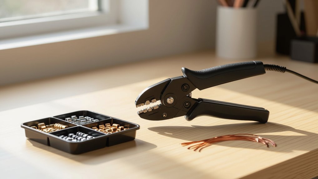
A crimper is a hand tool designed to compress metal terminals onto wire ends to form secure electrical or mechanical connections. Various models—from simple pliers to ratcheting and hydraulic units—match different connector styles and wire gauges for applications ranging from automotive wiring to telecommunications.
Commonly crimped components include insulated and non-insulated terminals, ferrules, and coax or RJ-style connectors paired with appropriately sized conductors.
Definition and purpose of a crimper
Crimping tools compress and deform connectors or terminals onto wires or hose fittings to create a secure mechanical and electrical joint. A crimper provides consistent pressure and alignment, preventing loose connections, signal loss, or leaks.
It enables reliable strain relief and conductivity across installations. Understanding how to set crimpers guarantees correct die selection, proper force, and repeatable, code-compliant terminations for professional results.
Types of crimping tools and common applications
Tools for crimping range from simple hand pliers to hydraulic and battery-powered machines, each designed for specific connector types and volumes of work.
Selection depends on scale, precision, and accessibility.
- Hand crimpers: low volume, portable, useful for field tasks.
- Ratcheting crimpers: consistent force for repeatable crimps.
- Hydraulic/battery units: high volume or larger terminals, workshop use.
Overview of connectors and wires suited for crimping
Many electrical and mechanical assemblies rely on crimped connections because they provide reliable, low-resistance joins without solder. The section identifies compatible connectors and wires, emphasizing conductor size, insulation type, and application environment.
- Insulated and non-insulated terminals for solid and stranded conductors.
- Ferrules for fine-stranded wire to prevent fraying.
- Coax, signal, and power-specific terminals with matching crimper dies.
Quick Answer: How to Set a Crimper for Perfect Crimps
A concise setup pairs the correct die, calibrated pressure, and aligned wire for a reliable crimp.
Before crimping, the operator should check die selection, crimper calibration, wire size and conductor exposure, and a secure workpiece position.
Confirming these factors minimizes rework and guarantees consistent, strong crimps.
One-sentence summary of the optimal setup
Set the crimper to the die and pressure settings that match the connector size and wire gauge. Align the cable fully into the jaw, and perform a test crimp on scrap to confirm correct depth and compression.
Use consistent hand force, guarantee the connector sits squarely, verify insulation and conductor placement, and adjust pressure incrementally until crimps are uniform, secure, and free of deformation.
Key success factors to check before crimping
Before crimping, inspect that the correct die and pressure settings match the connector and wire gauge.
Ensure the conductor and insulation are seated to the prescribed depth.
Verify that the connector sits squarely in the jaw, and that the tool and workpiece are clean and undamaged.
- Verify die/pressure versus specification.
- Confirm seating depth and alignment.
- Check tool condition and connector integrity.
Tools and Materials You Need Before Setting the Crimper
Before setting the crimper, the user should verify key tool features such as ratcheting mechanisms, interchangeable dies, and adjustment controls.
They should also identify the connector type required (butt, ring, spade; insulated or non‑insulated) and confirm wire specifications including gauge, stranded versus solid conductors, and insulation material.
Optional but recommended items include a wire stripper, multimeter, and heat gun for finishing and testing.
Essential crimper features to inspect (ratcheting, dies, adjusters)
A careful inspection of the crimper’s mechanical features guarantees reliable, consistent crimps and prevents damage to terminals or the tool.
Verify ratcheting action engages and releases smoothly, ensuring full cycle completion.
Inspect dies for correct size, clean mating surfaces, and wear or deformation.
Check adjusters and tension settings for repeatable pressure, secure locks, and easy calibration to specified crimp profiles.
Connector types: butt, ring, spade, insulated vs. non-insulated
Connectors come in distinct forms—butt, ring, and spade—and in insulated or non‑insulated varieties, each chosen to match the conductor, application, and crimping die.
Butt connectors join two wires inline; ring terminals secure to studs; spade terminals slip under screw heads.
Insulated types provide strain relief and electrical isolation; non‑insulated offer lower profile and higher current capacity where insulation isn’t required.
Wire specifications: gauge, stranded vs. solid, insulation type
Choosing the correct wire complements the connector selection and secures a reliable crimp. The technician evaluates wire gauge, conductor type, and insulation to match connector specifications and application environment.
- Gauge: verify AWG compatibility for current capacity and crimp die fit.
- Conductor: stranded for flexibility, solid for rigidity and stable insertion.
- Insulation: choose temperature and chemical resistance appropriate to the job.
Optional tools: wire stripper, multimeter, heat gun
Prepare several optional tools—wire stripper, multimeter, and heat gun—that streamline preparation and verification steps before setting the crimper.
A quality wire stripper guarantees consistent insulation removal without nicking conductors.
A multimeter verifies continuity, polarity, and resistance after crimping.
A heat gun shrinks tubing or activates adhesive-lined connectors for durable insulation.
These tools improve accuracy, safety, and long-term reliability of crimped connections.
Step-by-Step Guide to Setting the Crimper
The procedure begins by selecting the correct die or jaw for the connector and matching the crimper setting to the wire gauge and connector type.
Next, the operator adjusts crimp height or pressure using the dial or screw, then prepares the wire by stripping to the proper length and inspecting the conductor.
Finally, the wire and connector are positioned correctly in the die before the crimp is executed.
Step 1 Select the correct die or jaw for the connector
Begin by identifying the exact connector type and its corresponding die or jaw size specified by the manufacturer.
The technician verifies die compatibility with connector geometry—insulation support, barrel length, and crimp profile.
Inspect die condition for wear or distortion. Confirm part numbers and secure the chosen die in the crimper per tool instructions.
Avoid using mismatched dies that can deform or loosen connections.
Step 2 Match crimper setting to wire gauge and connector type
Match the crimper’s force and stroke to the wire gauge and connector type by consulting the connector manufacturer’s crimp specification chart and the tool’s setting range.
The operator verifies conductor strand count and insulation, selects corresponding crimp profile, and confirms compatibility with application (signal, power, or shielded).
Record recommended range for repeatability and reference before any production crimping.
Step 3 Adjust crimp height or pressure (dial or screw settings)
Adjust the crimp height or pressure using the tool’s dial or screw mechanism to align with the previously selected crimp profile and conductor specifications.
Rotate incrementally, noting meter or scale indicators when present. Use manufacturer torque or pressure guidelines as a baseline.
Perform one or two test crimps on sample material, inspect deformation and retention, then fine-tune until consistent, secure crimps are achieved.
Step 4 Prepare the wire: strip length and conductor condition
Strip the insulation to the manufacturer’s specified length and verify the conductor is clean, straight, and free of nicks or frayed strands before inserting it into the terminal.
Use a calibrated stripper to avoid nicking, removing only insulation. Inspect strand alignment, trim damaged wires, and untwist stranded conductors to the specified degree.
Confirm conductor exposure matches terminal cup depth for reliable contact.
Step 5 Insert wire and connector correctly before crimping
Position the prepared conductor into the terminal cup so the conductor insulation butts against the connector entrance and the bare strands reach the full depth of the cup without splaying.
Align the connector in the die, ensuring correct orientation and seating.
Verify insulation remains outside the crimp zone, strands are compacted, and no foreign debris is present before proceeding to crimp.
Step 6 Execute the crimp using proper technique (angle, squeeze)
Begin the crimp by seating the connector fully in the die and applying a steady, controlled squeeze until the tool cycles to its stop or the ratchet releases.
Maintain the tool perpendicular to the wire axis, avoid twisting, and use consistent pressure.
Hold the crimper steady as jaws close, ensuring insulation and conductor align correctly.
Do not re-crimp or adjust while compressed.
Step 7 Release and inspect the initial crimp
Release the crimper by allowing the ratchet or latch to open fully, then remove the connector and wire assembly from the jaws for inspection.
Visually and tactilely check crimp alignment, deformation, and conductor bite. Confirm insulation support, absence of burrs, and that the crimp barrel compresses evenly without splitting.
Document any irregularities and note required adjustments before proceeding to further testing.
Step 8 Make fine adjustments and perform a test crimp
Having inspected the initial crimp for alignment, deformation, and conductor bite, the operator now proceeds to make fine adjustments to the die gap and pressure settings based on documented observations.
After each incremental change, a controlled test crimp is performed, measured against specification for pull-out force and visual criteria.
If results meet criteria, settings are locked; if not, repeat adjustments until compliant.
Visual and Measurement Checks for a Correct Crimp
A correct crimp is identified visually by proper barrel deformation and visible insulation support without wire strand damage.
Mechanical verification typically includes a pull test and torque checks where specified.
Electrical confirmation is achieved through continuity and low-resistance measurements to guarantee reliable conductivity.
What a good crimp looks like (barrel deformation, insulation support)
Several clear indicators distinguish a correct crimp from a faulty one: uniform barrel deformation, visible insulation support, and proper conductor bite without strand damage.
- Barrel: even compression, no splits, consistent oval or hexagonal profile.
- Insulation: buttressed by the crimp sleeve, preventing axial movement.
- Conductor: strands compacted, no fraying, metal-to-metal contact ensuring electrical continuity and low resistance.
Mechanical checks: pull test and torque where applicable
Verify mechanical integrity of a crimp through simple, repeatable tests that quantify retention and torque where applicable.
Perform a controlled pull test, noting failure mode and load at separation; compare to specification.
For threaded or bolted terminals, apply calibrated torque wrench to verify clamp retention without deforming the crimp.
Record results, reject samples outside tolerance, and adjust tooling or process accordingly.
Electrical checks: continuity and resistance measurement
Begin electrical checks with straightforward continuity and low-resistance measurements to confirm that the crimp provides an intact, low-impedance electrical path.
Use a calibrated multimeter or micro-ohmmeter, record resistance, and compare to spec. Verify no intermittent contact by wiggling under load.
Repeat tests for each termination, documenting values and rejecting crimps that exceed allowable resistance or show unstable readings.
Common Crimping Problems and How to Fix Them
Common crimping problems — such as loose crimps causing intermittent connections, over-crushed connectors, insufficient insulation support, and damaged or nicked conductors — are identified by specific visual and electrical symptoms.
Each fault has a direct remedy: adjust die pressure and feed length to tighten loose crimps, reduce pressure or replace crushed terminals, reposition and trim insulation for proper support, and discard or re-strip damaged wires before re-crimping.
Addressing these issues promptly prevents failures and guarantees consistent crimp quality.
Loose crimps and intermittent connections causes and remedies
Loose crimps and intermittent connections often arise from improper conductor insertion, insufficient crimp pressure, worn dies, or mismatched terminal and wire sizes; identifying the root cause requires inspection of the crimp’s shape, retention, and continuity under slight axial and flexing stress.
Remedies include reterminating with correct strip length, verifying conductor placement, adjusting pressure, replacing worn dies, and matching terminals to wire gauge, followed by continuity testing.
Over-crimped (crushed) connectors how to avoid and recover
While insufficient pressure creates intermittent contacts, applying too much force can collapse the terminal and sever or deform conductors, producing an over-crimped (crushed) connector that fails mechanically or electrically.
To avoid this, verify crimper die selection, set calibrated pressure, inspect sample crimps for wire integrity, and replace damaged terminals.
Recovery requires replacing crushed connectors and evaluating wire ends for reuse readiness.
Insufficient insulation support adjustments to prevent slippage
Make certain the crimper provides adequate insulation support to prevent conductor slippage and maintain strain relief.
Adjust jaw alignment and depth settings so the insulation grip zone compresses without deforming the wire.
Use the correct die size for connector barrel and insulation.
Test with sample crimps, inspect for visible insulation capture, and fine-tune pressure until grips hold under light tensile force consistently.
Damaged conductors or nicked wires prevention and correction
Inspecting for damaged or nicked conductors is essential because compromised strands reduce electrical continuity and weaken mechanical strength.
Technicians should examine insulation and conductors before crimping, trim back and re-strip to undamaged wire if nicks are found, and discard severely damaged cable.
Use correct die size, controlled crimp pressure, and proper wire insertion depth to prevent recurrence and guarantee reliable connections.
Tips for Consistency and Quality Control
Consistency is maintained by establishing repeatable machine settings for each production run and recording them for specific wire and connector combinations.
Color-coded or labeled dies speed tooling changes and reduce setup errors, while scheduled inspection criteria indicate when dies, jaws, or the crimper itself require replacement.
A concise log of settings, wear observations, and replacement dates supports quality control and traceability.
Establishing repeatable settings for production work
Documenting and locking in specific crimper settings—pressure, die alignment, feed rate, and cycle timing—ensures each part meets the same dimensional and mechanical criteria across runs.
Operators should record validated settings per part number, enforce change control, and use calibrated gauges to verify output.
Implement periodic audits, statistical process control charts, and corrective action procedures to detect drift and maintain consistent, reproducible crimps in production.
Using color-coded or labeled dies for quick selection
After locking in validated settings and recording them by part number, operators can further reduce setup time and error rates by using color-coded or clearly labeled dies for quick selection.
- Match die color/label to part number and wire size for immediate identification.
- Store dies in labeled trays to prevent mix-ups and speed changeovers.
- Update labels when specs change to maintain traceability and audit readiness.
When to replace dies, jaws, or the crimper
When should dies, jaws, or the entire crimper be replaced to preserve part quality and process reliability?
Replace dies or jaws when wear, cracking, galling, dimensional drift, or repeated out-of-spec crimp results occur despite adjustment.
Replace the crimper if recurring mechanical failures, alignment loss, or safety compromises appear.
Track replacement triggers via inspection intervals and reject rate thresholds to maintain consistency and control.
Documenting settings for different wire/connector combinations
Maintaining clear records of crimper settings for each wire and connector combination prevents repeated adjustment errors and supports traceability when dies or jaws are replaced.
Log wire gauge, insulation type, connector model, die/jaw ID, pressure or force, indentation depth, and successful pull-test results.
Store versions, operator initials, date, and any deviations.
Review logs during setup and audits to guarantee consistent, repeatable crimps.
Comparison of Manual, Ratcheting, and Hydraulic Crimpers
Selection of a crimper should match expected production volume and the range of connector sizes to guarantee consistent crimps and operator efficiency. Manual tools suit low-volume or varied-size work, ratcheting crimpers balance speed and control for moderate runs, and hydraulic units excel in high-volume or large-connector applications. The table below summarizes suitability by volume and connector size.
| Crimper Type | Best Use Case |
|---|---|
| Manual | Low volume, varied small connectors |
| Ratcheting | Moderate volume, consistent small–medium connectors |
| Hydraulic | High volume, large connectors |
Best crimper type by volume and connector size
Different workflows demand different crimper types: manual pliers suit low-volume, small-connector tasks; ratcheting crimpers balance speed and consistency for moderate runs and common terminal sizes; hydraulic units excel for high-volume or large-gauge connectors where force and repeatability are critical.
- Manual: precise, portable, best for occasional small gauges.
- Ratcheting: consistent, faster, ideal mid-volume production.
- Hydraulic: powerful, repeatable, necessary for heavy-gauge, mass work.
Safety Precautions and Best Practices
Before using a crimper, the operator should wear appropriate personal protective equipment and arrange a well-lit, uncluttered workspace.
Sharp tools and tiny connectors must be handled with controlled motions and proper tweezers or holders to prevent cuts and accidental loss.
Damaged connectors and cut wire should be collected and disposed of in a designated container to avoid injury and contamination.
Personal protective equipment and workspace setup
Proper personal protective equipment (PPE) and an organized workspace minimize injury risk and guarantee consistent crimps.
The technician prepares a clean, well-lit bench, secures components, and keeps documentation accessible.
PPE includes eye protection, cut-resistant gloves, and hearing protection when needed.
Maintain clear cord management and a stable mat to prevent slips.
- Eye protection
- Cut-resistant gloves
- Stable, well-lit bench
Safe handling of sharp tools and small connectors
Handle sharp tools and tiny connectors with deliberate care to prevent cuts, punctures, and loss of parts.
Store blades and picks in sheaths or magnetic trays when not in use. Use tweezers or pliers for small components to avoid fingertips.
Keep work area well lit and uncluttered. Inspect tools before use and secure connectors in jigs to guarantee stable, controlled operations.
Disposal of damaged connectors and cut wire
Dispose damaged connectors and cut wire promptly to reduce injury risk, prevent short circuits, and keep the work area orderly.
Used components should be collected in a designated, puncture-resistant container. Label and seal the container when full, then follow local electronic waste regulations for disposal or recycling.
Record disposal of hazardous items per workplace policy and avoid leaving scraps on benches or floors.
Example Scenarios and Recommended Settings
The following examples present specific crimping scenarios and the recommended setting ranges for each application.
Settings for 22–18 AWG insulated terminals, 12–10 AWG automotive ring terminals, and 26–30 AWG small signal connectors are given with step-by-step notes where necessary.
Readers should use these as starting points and verify each crimp for correct deformation and pull strength.
Crimping 22 to 18 AWG insulated terminals step-by-step settings
When preparing to crimp 22 to 18 AWG insulated terminals, technicians should follow a concise sequence of adjustments—selecting the correct die, setting stroke and pressure, and verifying conductor insertion depth—to guarantee reliable electrical and mechanical connections.
Choose the die for 22–18 AWG, set minimal effective stroke, adjust pressure to compress insulation without crushing, insert stripped conductor to collar, perform test crimps, and inspect pull strength.
Crimping 12 to 10 AWG ring terminals for automotive use
Moving from smaller insulated terminals to heavier-duty ring terminals requires adjustments in tooling and settings to handle larger conductors and higher current loads.
Use a hex or indent die sized for 12–10 AWG; select heavy-duty jaws and higher crimp force.
Strip length should expose full barrel without stray strands.
Inspect for full metal displacement, secure mechanical pull test and corrosion protection.
Crimping small signal connectors for electronics (26 to 30 AWG)
Handle small-signal crimping with delicate control: 26–30 AWG wires require precise die geometry, light consistent force, and minimal insulation displacement to preserve conductor integrity and signal fidelity.
Use micro‑dies or insulated blade dies, set stroke shallow, and dial tension low. Verify pull strength, conductor continuity, and absence of insulation intrusion.
For stranded litz conductors, use solder‑tinned or ferrule support before crimping.
Troubleshooting Checklist Before Assuming Equipment Failure
Begin with a systematic checklist that verifies setup and basic function before concluding the crimper is defective.
Inspect jaws, dies, and fastening hardware for wear or misalignment. Confirm correct die size and wire/connector match.
Verify calibration and test with a known-good sample. If issues persist, consult manual or supplier before replacing tools.
- Visual inspection
- Functional test
- Calibration verification
Conclusion
A properly set crimper transforms loose wire and mismatched terminals into reliable, long-lasting connections. Testing the theory that precise die selection, correct crimp pressure, and consistent technique prevent electrical failures reveals predictable, repeatable results across applications. Adhering to measurements, tool type, and safety practices produces crimps that pass pull and continuity tests. Continued inspection and occasional recalibration sustain performance, proving that meticulous setup—not luck—yields perfect crimps every time.