How to Change a Water Heater Pressure Relief Valve: Step-by-Step DIY Guide
To change a water heater temperature-and-pressure (T&P) relief valve, start by shutting off the power or gas and the cold-water supply. Next, relieve the tank pressure and drain water below the valve level. Wear appropriate safety gear, then loosen and remove the old valve. Inspect the threads, apply Teflon tape or sealant, and install the new valve that meets specifications. Reconnect the discharge piping, and finally, test for leaks and proper operation. Always adhere to local codes and manufacturer guidelines for a safe installation.
What a Water Heater Pressure Relief Valve Does and Why Replacement May Be Necessary
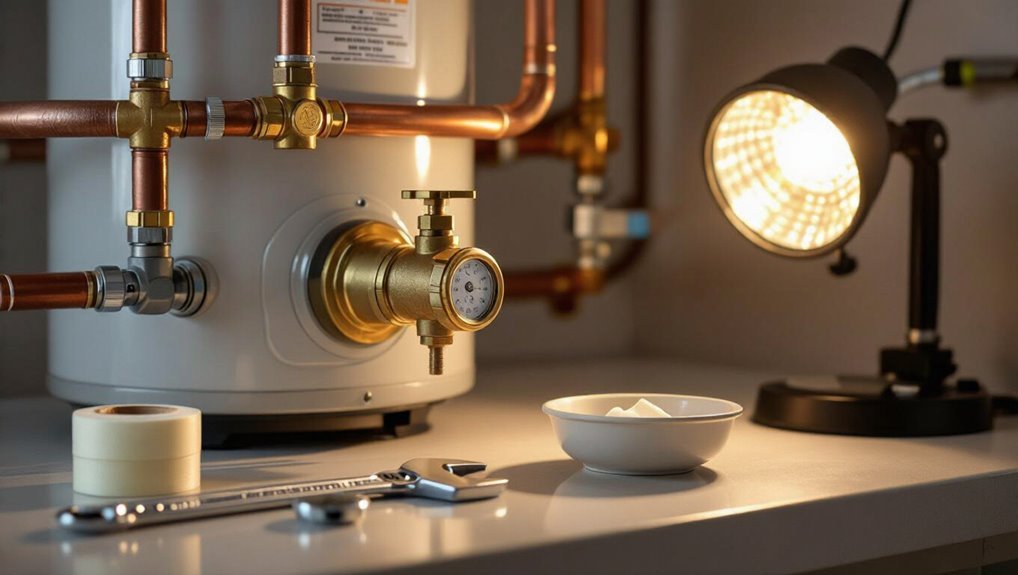
The temperature-and-pressure (T&P) relief valve prevents excessive pressure or overheating in the water heater by opening to release water when preset limits are exceeded.
Signs that the valve may need replacement include continuous dripping, visible corrosion, stiffness when manually tested, or repeated trips under normal conditions.
A malfunctioning valve poses serious safety risks, such as tank rupture or scalding, so timely inspection and replacement are important.
Function of the temperature and pressure (T&P) relief valve
Guarding both homeowners and the water heater itself, the temperature-and-pressure (T&P) relief valve prevents dangerous pressure buildup or overheating by opening to release water when preset limits are exceeded.
It senses both temperature and pressure, discharging automatically to protect tank integrity.
Understanding this function is essential before attempting DIY tasks like how to change pressure relief valve on water heater safely and correctly.
Common signs that indicate the valve needs replacement
After explaining how a T&P relief valve protects against overheating and overpressure, attention turns to recognizing when the valve itself may be failing.
Common signs include persistent dripping from the discharge pipe, visible corrosion or mineral buildup on the valve, valve not seating properly after a manual lift test, sudden loud noises from the heater, and age-related deterioration beyond the manufacturer’s recommended service life.
Safety risks of a faulty pressure relief valve
Recognized as a last-resort safety device, a temperature-and-pressure (T&P) relief valve prevents catastrophic failure by releasing excess pressure or scalding steam from a water heater.
When it malfunctions, risks escalate to explosive tank rupture, scalding discharge, and water damage.
Corroded, stuck, or leaking valves can flood property, cause burns, compromise structural integrity, and create mold hazards—prompt replacement mitigates these dangers.
Tools, Materials, and Safety Equipment Needed
The section lists the specific tools required and the correct replacement valve specifications to guarantee compatibility and safe operation.
It also covers necessary materials, common fittings, and optional adapters that may be needed for different plumbing configurations.
Finally, it outlines personal protective equipment and key safety precautions to minimize injury and prevent water or pressure-related hazards.
Required tools and replacement valve specifications
Gathering the right tools, materials, and safety equipment guarantees a smooth, code-compliant replacement of a water heater pressure relief valve.
Required tools include an adjustable wrench, pipe wrench, and Teflon tape; a replacement valve must match temperature/pressure ratings and thread size.
Safety gear includes gloves and eye protection.
- Wrenches and thread sealant
- Correct valve specifications
- Personal protective equipment
Materials, fittings, and optional adapters
Materials for replacing a pressure relief valve should include a correctly rated relief valve, a short length of discharge piping, and compatible fittings to connect to the heater outlet; optional adapters—such as a dielectric union or male/female pipe adapters—can accommodate differing thread types or materials.
Required materials and common adapter choices are listed below.
- Replacement valve and Teflon tape
- Discharge pipe and elbow fittings
- Dielectric unions or thread adapters
Personal protective equipment and safety precautions
Wear chemical-resistant gloves, eye protection, and sturdy closed-toe shoes before beginning work on a water heater pressure relief valve to reduce the risk of burns, scalding, or chemical exposure; additionally, use hearing protection if power tools are involved and a face shield when draining or flushing the tank to prevent splash injuries.
- Protective gear: gloves, goggles, face shield, hearing protection
- Fire and electrical safety: shut off power, vent gas
- Worksite controls: clear area, have a helper, keep a fire extinguisher nearby
How to Select the Right Pressure Relief Valve
Selecting the correct pressure relief valve begins with confirming the water heater’s required pressure and temperature ratings to guarantee proper protection.
The installer must also match the valve’s thread size and connection type to the tank fitting for a secure, leak-free installation.
Finally, consideration should be given to valves designed for discharge piping compatibility when local code or installation layout requires a piped relief.
Determining correct pressure and temperature ratings
Choose a pressure relief valve whose maximum pressure and temperature ratings meet or exceed the water heater’s design limits and local code requirements.
Verify the heater nameplate for maximum working pressure (typically 150–300 psi) and temperature.
Select a valve rated for at least those values, often 150 psi/210°F for residential units.
Confirm compatibility with system operating pressure and any specialized high-temperature applications.
Matching thread size and connection type
When replacing a temperature and pressure relief valve, confirming the valve’s thread size and connection type is essential to guarantee a proper fit and a leak-free seal.
Inspect the tank outlet for thread designation (commonly 3/4″ NPT) and note whether the valve uses male or female threads, union fittings, or flanges.
Match materials and taper to prevent cross-threading and corrosion.
When to choose a valve with discharge piping compatibility
For installations where the relief valve will discharge into a drain, outdoors, or a mechanical venting system, compatibility with discharge piping becomes a primary selection criterion.
Choose valves with approved outlet sizes, corrosion-resistant materials, and pressure-temperature ratings matching local codes.
Guarantee alignment with required pipe fittings, trap-free slopes, and accessible inspection points.
Confirm manufacturer guidance for safe, code-compliant discharge routing.
Step-by-Step Preparation Before Replacement
Before beginning the replacement, power or gas to the water heater should be shut off and the cold-water supply closed to prevent incoming flow.
The tank must be depressurized and drained to the level needed for safe access, with the work area isolated to avoid spills.
Surrounding plumbing should be inspected and the existing configuration documented to guarantee correct reassembly.
Shutting off power or gas to the water heater
Shut down the water heater’s energy source to eliminate the risk of fire, electric shock, or scalding while replacing the pressure relief valve.
For electric units, turn off the dedicated circuit breaker and confirm with a non-contact voltage tester.
For gas models, set the thermostat to “pilot” or shut the gas valve to off per manufacturer instructions.
Guarantee adequate ventilation before proceeding.
Turning off the cold-water supply and relieving tank pressure
Locate and close the cold-water supply valve feeding the heater to isolate the tank from incoming mains pressure.
Next, open a nearby hot-water faucet and lift the pressure relief lever slightly to vent trapped pressure; audible hissing indicates release.
Allow several minutes for internal pressure equalization.
Confirm no additional inlet flow at the closed valve before proceeding with further preparatory steps.
Draining water to the appropriate level and isolating the workspace
With the cold-water supply closed and pressure relieved, the next step is to lower the tank’s water level to a point below the relief valve outlet and create a safe work area around the heater.
Attach a hose to the drain valve and open it into a floor drain or bucket. Monitor flow until the level is sufficiently low, then clear flammable materials and provide adequate lighting and access.
Inspecting surrounding plumbing and documenting current setup
Before removing the valve, examine and record the existing plumbing layout: note pipe materials (copper, CPVC, galvanized), fitting types, valve locations and orientations, any unions or adapters, and the position of the temperature-pressure relief (TPR) discharge line relative to walls and drains.
Photograph connections, measure clearances, and log thread types and sizes for replacement planning.
- Photograph and sketch setup
- Note materials and fittings
- Record clearances and discharge path
Step-by-Step Guide to Remove the Old Pressure Relief Valve
The technician first locates the relief valve, checks for any discharge, and confirms whether additional draining is required.
If necessary, a bucket or hose is positioned and the tank is drained enough to lower the water level below the valve.
The old valve is then loosened and removed with care, and the opening and threads are inspected for damage.
Locating the valve and testing existing discharge
One clear starting point is to identify the temperature-pressure relief (T&P) valve and observe any existing discharge before attempting removal.
Inspect its location—usually on the tank’s top or side—and note a discharge pipe leading downward.
Check for recent leaks, mineral buildup, wetness, or corrosion at the outlet.
Operate the lever briefly to confirm flow and listen for pressure-related noises.
Draining additional water as needed and placing a bucket or hose
Drain enough water from the tank to lower the level below the valve opening so liquid won’t spill when the relief valve is removed.
Use the drain valve at the tank base, attaching a hose directed to a floor drain or outside.
If space is limited, position a sturdy bucket beneath the discharge pipe.
Monitor flow and stop when the water level is safely below the relief port.
Loosening and removing the old valve safely
Begin by confirming that the gas or electric supply is off and the water heater is cool.
Then place a towel or catch pan beneath the relief valve to contain any residual drips.
Using an adjustable wrench, turn the valve counterclockwise while holding the fitting steady.
Apply steady force; if stuck, use penetrating oil and wait.
Remove the valve and drain any remaining drips into the pan.
Inspecting the valve opening and threads for damage
With the valve removed, the opening and threads should be examined immediately for corrosion, cross-threading, cracked metal, or trapped debris that could prevent a proper seal.
The inspector notes thread integrity, cleans deposits with a brass brush, and wipes surfaces.
Any gouges, flattened threads, or rust pitting warrant repair or replacement of the tank fitting; minor debris may be cleared and retested before installing the new valve.
Step-by-Step Guide to Install the New Pressure Relief Valve
The installer begins by preparing the valve threads with appropriate pipe sealant or plumber’s tape. Then, they insert the new valve by hand before applying the recommended torque with a wrench.
Next, the discharge pipe or elbow is reattached and securely fastened to direct any relief flow safely away from surrounding areas.
Finally, the water supply is restored and the assembly is inspected for leaks while the system reaches operating pressure.
Preparing threads: applying sealant or plumber’s tape correctly
Before installing the new pressure relief valve, make certain the threads are clean and dry so sealant or plumber’s tape can bond properly.
Remove old tape or sealant with a wire brush or rag and inspect threads for damage.
Apply plumber’s tape clockwise three to five wraps, smoothing each wrap, or cover male threads with a thin, even coat of approved pipe thread sealant, avoiding excess.
Hand-tightening and torque guidance for insertion
Start threading the new pressure relief valve by hand, ensuring it engages squarely and turns smoothly without cross-threading.
Continue hand-tightening until snug, then use a wrench to apply a final quarter to half turn—typically 15–30 ft·lb for common valves—avoiding overtightening.
Check for alignment and thread seating; excessive torque can warp fittings or strip threads, so proceed incrementally and re-evaluate fit.
Reattaching and securing discharge piping or elbow
Reconnect the discharge piping or elbow to the relief valve, aligning the outlet so the pipe directs discharge to a safe, visible location.
Apply thread sealant or tape where required, then tighten fittings securely without overtorquing.
Support the pipe with straps or brackets to prevent strain on the valve.
Confirm the discharge tip remains unobstructed and terminates to an appropriate drain or containment point.
Restoring water supply and checking for leaks
Open the cold-water feed valve slowly to reintroduce water to the tank, then observe the valve and newly attached piping for any signs of leakage.
Allow the tank to fill fully, venting trapped air at the hot faucet.
Inspect connections, joints, and the discharge elbow for drips.
Tighten fittings if necessary, then run a pressure test and recheck after several minutes to confirm watertight integrity.
Post-Installation Tests and Verification
After installation, the technician performs a controlled manual test of the relief valve to confirm proper opening and resealing.
They inspect the valve and drain path for continuous leaks or obstructions while verifying the water heater’s pressure and temperature settings remain within safe limits.
If inconsistencies appear or the tank has been notably depressurized, a full system test or controlled re-pressurization is conducted before completing the job.
Performing a controlled test of valve operation
Begin the controlled test by confirming the system is pressurized to normal operating pressure and the tank is at its target temperature.
Then position a bucket or hose beneath the relief valve outlet to capture discharge.
Manually lift the valve lever briefly to actuate flow, observe immediate, steady discharge and reseating when released.
Note any hesitation or dribble, and record results for maintenance.
Checking for continuous leaks and proper drainage path
Several checks confirm there are no continuous leaks and that the relief valve discharges to a safe, unobstructed path: inspect the valve, discharge pipe, and nearby fittings for any steady moisture or drips; verify the discharge pipe slopes downward and terminates above a suitable drain or outside away from walkways and foundations; and ascertain all joints and the pipe-to-fitting connections are tight, corrosion-free, and properly supported to prevent strain that could cause future leaks.
Afterwards, observe the system over several hours while under normal pressure to verify no slow seepage, water pooling, or condensation occurs, and confirm the drain outlet remains clear and free-flowing.
Verifying heater pressure and temperature settings
Verify that the water heater pressure and temperature settings are within safe operating ranges before completing the job.
Measure system pressure with a gauge at a nearby cold-water faucet; confirm pressure stays below 80 psi.
Check thermostat setpoint; typical safe maximum is 120–125°F.
Adjust controls if readings exceed limits.
Record final values and note any irregular fluctuations for follow-up.
When to run a full system test or re-pressurize the tank
When should a full system test be run or the tank re-pressurized after replacing a pressure relief valve?
A full test and re-pressurization should occur only after the new valve is installed, all connections are tight, drains cleared, and the system is visually leak-free.
Perform tests at normal operating pressure and temperature, monitor for leaks or unusual noises, and verify valve function before resuming regular use.
Troubleshooting Common Problems After Replacement
Following replacement, common issues such as an immediately leaking new valve, a valve that sticks or fails to reseat, and persistent high system pressure are addressed with clear diagnostics and corrective steps.
Causes for an immediate leak, like improper thread sealant or misaligned fittings, and their fixes are outlined first.
Procedures for testing and correcting a sticking valve and for identifying and remedying sustained overpressure—including tank temperature, expansion tank status, and pressure-reducing valve adjustment—are then summarized.
New valve leaking immediately causes and fixes
If a newly installed temperature and pressure relief (T&P) valve begins to drip or flow immediately, the problem usually traces to installation errors, incompatible parts, or residual system conditions rather than a defective valve.
Check that the valve is the correct model and size, tightened to manufacturer torque, installed upright, with a clear discharge line.
Flush trapped debris, verify system pressure and thermal expansion controls.
Valve sticking or failing to reseat diagnostic steps
Inspect the valve mechanism and surrounding system to pinpoint why a newly installed T&P relief valve sticks or fails to reseat.
Check for debris, mineral buildup, or packaging remnants preventing closure.
Verify correct valve orientation, proper seating torque, and compatible valve type.
Inspect discharge piping for backpressure and confirm the lever moves freely.
Replace valve if internal defect or warped seat is suspected.
Persistent high pressure in the system and corrective actions
Address persistent high pressure promptly to prevent repeated T&P valve discharge, premature component failure, or safety hazards.
The homeowner should measure static and running pressure with a gauge, check thermal expansion due to closed systems, and inspect PRV and expansion tank functionality.
Corrective actions include installing or recharging an expansion tank, replacing a faulty PRV, or adjusting/repairing upstream pressure regulators.
Maintenance, Lifespan, and Replacement Interval Guidelines
Regular visual and manual checks—at least twice yearly—should confirm the relief valve is free of corrosion, leakage, mineral buildup, and operates when briefly lifted.
Valves typically last 3–6 years but may need earlier replacement due to hard water, frequent pressure spikes, or visible failure.
A licensed plumber should be called for signs of persistent leakage, repeated activations, or uncertain installation, while simple inspections and a single controlled test can be handled by a competent homeowner.
Routine inspection schedule and what to look for
A homeowner should check the temperature and pressure relief (T&P) valve every six months as part of routine water heater maintenance.
Inspect for leaks, corrosion, and proper discharge flow when tripped. Verify discharge piping is intact and directed safely.
- Look for drips, rust, or mineral buildup.
- Test manual trip for clear flow.
- Confirm piping and termination point.
Recommended replacement intervals and factors that shorten lifespan
After confirming T&P valve operation and discharge routing during biannual checks, homeowners should plan for eventual replacement based on both time and condition.
Typical service life is 3–7 years; replace sooner if leaks, mineral buildup, corrosion, stiff or stuck lever, repeated discharges, or frequent temperature/pressure spikes occur.
Hard water, high corrosion, and neglect shorten lifespan and warrant earlier replacement.
When to call a licensed plumber versus DIY
Homeowners should assess complexity, risk, and their own skill level before attempting T&P valve work.
Simple replacements with shutoff and drain control may suit competent DIYers.
Call a licensed plumber if corrosion, leaks at fittings, repeated trips, high pressure, gas connections, unfamiliar codes, or lack of proper tools exist.
Professional service guarantees safety, warranty compliance, and reliable diagnosis of underlying system issues.
Cost Estimates and When Professional Service Is Advisable
A concise cost comparison helps owners decide between a DIY replacement and hiring a pro, outlining typical parts and basic tools versus labor and service fees.
DIY expenses commonly include the relief valve ($10–$50), fittings and pipe dope ($5–$20), and any specialty tools if not already owned, while professional charges vary widely based on region, access, tank type, and emergency calls (often $150–$500+).
Immediate professional service is advisable for active leaks, signs of tank failure, electrical or gas complications, or unclear shutoff capability.
Typical DIY cost breakdown (parts and tools)
Most DIY replacements of a water heater pressure relief valve cost under $100 in parts and basic tools, though model and local prices vary. Typical items: replacement valve, short discharge pipe, Teflon tape, adjustable wrench, and possibly a flaring tool or tubing cutter. Budget breakdown:
| Item | Typical cost |
|---|---|
| Valve | $15–$50 |
| Tools/parts | $10–$40 |
Typical professional service costs and factors that affect price
When a homeowner opts for professional replacement of a water heater pressure relief valve, costs typically range from $100 to $300 but can climb higher depending on location, labor rates, and job complexity.
Additional cost factors include emergency or after-hours service, access difficulty, permit requirements, valve type, and disposal.
Estimates often cover labor, parts, travel, and basic testing; obtain written quotes.
Scenarios requiring immediate professional intervention
Recognize that certain pressure-relief valve issues demand immediate professional attention to prevent property damage or personal injury; situations include visible leaking under high pressure, continuous discharge, steam or boiling water ejection, rapid tank corrosion, gas-smell with a gas-fired heater, or failed shutoff causing uncontrolled pressure.
In these cases, contact a licensed plumber or HVAC technician immediately to assess, isolate, and replace components safely.
Common Mistakes to Avoid During Valve Replacement
Attention to common errors can prevent leaks, pressure hazards, and premature failures when replacing a water heater pressure relief valve.
Technicians and DIYers should be mindful of mechanical and compatibility issues to guarantee a safe, reliable installation.
The most frequent pitfalls include:
- Over-tightening or improper sealing
- Failing to depressurize or drain adequately
- Using incorrect valve rating or incompatible fittings
Over-tightening or improper sealing
Over-tightening the temperature and pressure relief (T&P) valve or applying sealing methods incorrectly can damage threads, distort valve seats, and compromise the valve’s ability to open under excess pressure.
Installers should hand-tighten then use a wrench for a quarter-turn, follow manufacturer torque specs, and use appropriate PTFE tape or pipe compound sparingly.
Recheck for leaks; avoid excess force.
Failing to depressurize or drain adequately
Failing to fully depressurize and drain a water heater before replacing the pressure relief valve can leave hot water and high-pressure steam trapped in the tank, creating a serious scald and rupture hazard during removal.
Technicians must shut off power/gas, isolate the cold-water feed, open a drain valve and a hot faucet, and verify pressure relief until flow stops.
Residual pressure risks injury.
Using incorrect valve rating or incompatible fittings
Select a relief valve and fittings that match the tank’s pressure-temperature rating and the plumbing connections; using an underspecified valve or incompatible threads can prevent proper operation, cause leaks, or damage the heater.
Incorrect pressure or temperature rating disables safety margins. Mismatched thread types or sizes cause cross-threading and leaks.
Use manufacturer specifications, compatible materials, and properly sized adapters to guarantee a safe, reliable installation.
Quick Checklist Before Finishing the Job
Before completing the job, the installer reviews a brief checklist to confirm the new pressure relief valve and associated fittings are secure, leak-free, and oriented correctly.
He verifies system pressure, drainage path, and venting compliance, confirming manufacturer specs and local code.
Then he tests operation and inspects for leaks before restoring normal operation.
- Confirm tightness and orientation
- Test valve operation and drain
- Verify pressure and code compliance
Conclusion
A surprising theory suggests most pressure relief valve failures stem not from age but from mineral buildup and minor installation errors. After following the step-by-step replacement and testing procedures, the DIYer can confirm or refute this: a properly fitted, correctly rated valve that discharges cleanly indicates installation or water quality issues rather than a defective part. Regular inspection and simple maintenance prove more effective at preventing failures than waiting for apparent age-related breakdown.