How to Adjust a Pressure Relief Valve: Step-by-Step Guide for Safe, Accurate Settings
A pressure relief valve is crucial for preventing overpressure in systems by opening at a predetermined point and closing when it’s safe. To adjust it accurately and safely, follow these steps:
- Preparation: Isolate the valve and depressurize the system. Use personal protective equipment (PPE) and follow lockout/tagout (LOTO) protocols.
- Adjustment: Loosen the locknut and make small adjustments to the set screw according to the manufacturer’s specifications.
- Verification: Use a calibrated test gauge to check the lift and reseat pressure.
- Securing: Tighten the locknut and document the new settings.
- Troubleshooting: If you encounter issues like leakage, chatter, or pressure drift, consult a specialist for persistent problems.
For detailed procedures, testing methods, and recordkeeping practices, refer to the additional sections provided.
What a Pressure Relief Valve Is and Why Proper Adjustment Matters
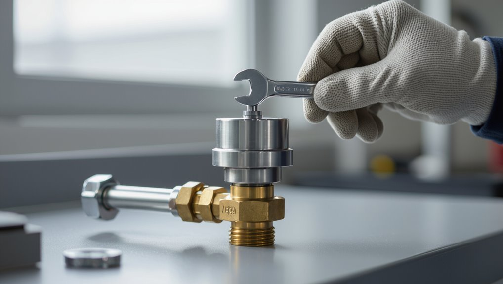
A pressure relief valve is a safety device that protects systems—such as boilers, compressors, and piping networks—by opening at a set pressure to prevent overpressure.
Incorrect adjustment can cause dangerous overpressurization, equipment failure, unnecessary releases, and violations of safety codes.
Relevant industry standards and local regulations define setpoint tolerances, testing, and documentation requirements that must be followed.
Purpose and common applications of pressure relief valves
Pressure relief valves protect equipment and personnel by limiting maximum system pressure: they automatically open to discharge excess fluid or gas when preset limits are exceeded, then reclose when normal conditions return.
They serve boilers, compressors, hydraulic systems, and pipelines, preventing overpressure events while ensuring operational continuity.
Guidance on how to adjust pressure relief valve settings optimizes performance and system compatibility across applications.
Risks of incorrect settings (safety, equipment damage, code violations)
Misadjusting a relief valve can quickly turn a protective device into a hazard, exposing personnel and equipment to serious risk.
Incorrect setpoints may cause overpressure, leading to ruptures, fires, or catastrophic release of fluids.
Chronic undersetting causes nuisance relief and corrosion, degrading systems and downtime.
Noncompliant settings invite violations, fines, and invalidated warranties, increasing liability and repair costs.
Relevant standards and regulations to consider
Why do codes and standards matter for relief-valve adjustment?
Industry codes (ASME, API, EN), local regulations, and manufacturer instructions define allowable set pressures, testing, documentation, and personnel qualifications.
Compliance guarantees safety, legal conformity, insurance validity, and system integrity.
Engineers must verify applicable standards, record adjustments, and follow required intervals and test methods to avoid violations and hazards.
How to Determine the Correct Relief Pressure for Your System
Determining the correct relief pressure begins with consulting system documentation and nameplate data to identify maximum allowable and normal operating pressures.
From there, the appropriate set pressure is calculated relative to the system’s maximum operating pressure while accounting for factors such as thermal expansion, MAWP, and backpressure.
If documentation is unclear or the system presents unusual conditions, an engineer or the valve manufacturer should be consulted.
Reading system documentation and nameplate data
A careful review of system documentation and equipment nameplates establishes the baseline for selecting the correct relief pressure.
Records, piping and vessel datasheets, design codes, and manufacturer manuals list maximum allowable working pressure (MAWP), design temperature, fluid type, and installation limits.
Nameplates on pumps and vessels provide model, serial, and rated pressures.
Verify revisions, applicable codes, and traceability before setting the valve.
Calculating set pressure from system maximum operating pressure
With the system’s MAWP and operating data confirmed from documentation and nameplates, the next step is to convert that information into a concrete set pressure for the relief valve.
Calculate set pressure by adding required safety margin above maximum operating pressure, complying with applicable code limits and manufacturer tolerances.
Round to available settings, document the chosen value, and verify compatibility with downstream equipment and piping.
Factors that affect set pressure choice (thermal expansion, MAWP, backpressure)
Because multiple system variables interact to influence safe relief settings, choosing the correct set pressure requires evaluating thermal expansion, the vessel’s MAWP, and backpressure together rather than in isolation.
Thermal expansion raises internal pressure during heating; MAWP limits the maximum allowable relief setting; backpressure (both constant and variable) affects effective lift and net relieving capacity.
All factors must be quantified and balanced.
When to consult an engineer or manufacturer
Given the interplay of thermal expansion, MAWP, and backpressure, situations will arise where standard tables and rules-of-thumb are insufficient to determine a safe set pressure.
Consult an engineer or manufacturer when systems have pulsation, two-phase flow, transient spikes, complex piping, unknown relief device interactions, or when certification, warranty, or regulatory compliance is required.
Document calculations and follow provided guidance.
Tools, Equipment, and Safety Precautions Needed Before Adjustment
Before adjusting a pressure relief valve, the technician should assemble required tools and testing equipment such as calibrated pressure gauges, wrenches, and leak-detection supplies.
Appropriate personal protective equipment must be worn and lockout/tagout procedures implemented to prevent accidental energy release.
The system should then be isolated, depressurized, and vented per procedures to guarantee a safe adjustment environment.
Required tools and testing equipment
A concise set of tools and calibrated testing equipment is essential to adjust a pressure relief valve safely and accurately.
The technician requires precise instruments and reliable instruments to verify setpoints and leak-free operation before returning the valve to service.
- Calibrated pressure gauge or deadweight tester
- Torque wrench with appropriate sockets
- Adjustable spanners and screwdrivers
- Portable data logger or digital manometer
Personal protective equipment and lockout/tagout procedures
Wear appropriate personal protective equipment (PPE) and implement lockout/tagout (LOTO) procedures to control hazards while adjusting a pressure relief valve.
Personnel should don safety glasses, gloves resistant to chemicals and heat, hearing protection, and flame-resistant clothing as required.
Establish LOTO per facility policy: isolate energy sources, tag controllers, verify zero energy, and restrict access until adjustments and safety verifications are complete.
Preparing the system for a safe adjustment (isolation, depressurization, venting)
Several critical steps guarantee the system is safe for adjusting a pressure relief valve: isolate the affected section, depressurize to verified zero-energy, and provide controlled venting of trapped fluids or gases.
Technicians confirm isolation with blinds or locked valves, bleed lines gradually to designated drains, verify zero pressure with calibrated gauges, and use appropriate containment and signage to prevent re-pressurization during adjustment.
Step-by-Step Procedure to Adjust a Screw-Loaded Pressure Relief Valve
A technician begins with an initial inspection to verify the relief valve is clean, undamaged, and isolated from system pressure.
Next, the bonnet or locknut is safely loosened or secured as required, and the set screw is adjusted in small increments with clear direction (clockwise to increase, counterclockwise to decrease) while monitoring system pressure.
After achieving the target set point, the adjustment is re-tightened and secured, and the new set pressure is recorded on the valve label and in maintenance logs.
Initial inspection and verification of valve condition
Before any adjustment, the technician performs a thorough initial inspection to verify the relief valve’s condition and readiness for calibration.
The process includes confirming correct valve identification and service history, checking for external damage, corrosion, leaks, and proper mounting, verifying tag data and setpoint documentation, ensuring isolation and depressurization are complete, and confirming access to nameplate information and necessary tools before proceeding.
Loosening or locking the bonnet/locknut safely
Loosen or secure the bonnet/locknut only after confirming the valve is isolated, depressurized, and tagged out; this prevents unintended discharge and protects personnel and equipment while preparing the screw-loaded mechanism for adjustment.
Using appropriate tools, back off the locknut or clamp the bonnet per manufacturer torque limits. Keep hands clear of outlets, note initial settings, and replace protective covers before re-pressurization.
Making small incremental adjustments and direction guidance
Begin by verifying the valve remains isolated and depressurized.
Make adjustments in small, consistent increments—typically quarter-turns or specified fractions—recording each change.
Rotate the adjusting screw clockwise to increase set pressure, counterclockwise to decrease.
After each increment, allow system stabilization, then test setpoint.
Continue until target pressure achieved, minimizing overshoot and documenting final position and observed pressure response.
Re-tightening and securing the adjustment mechanism
After each incremental adjustment and verification of the setpoint, the technician must re-tighten and secure the adjustment mechanism to preserve the achieved setting and prevent inadvertent movement.
Use the specified torque value, tighten locknuts, re-seat jam nuts, and engage safety clips or cotter pins where provided.
Confirm no binding, verify spring compression remains correct, and perform a final pressure check to guarantee stability.
Documenting the new set pressure on the valve
One clear, permanent record of the adjusted set pressure should be placed directly on the valve nameplate or an attached data tag to confirm future technicians can quickly verify the setting.
Additionally, log date, technician initials, calibration reference, and any test results in the maintenance database.
Ensure handwriting or engraving is legible, use corrosion-resistant materials, and cross-reference the valve ID for coordinated asset records.
Step-by-Step Procedure for Pilot-Operated and Spring-Loaded Valves
The following section outlines specific adjustment steps for pilot-operated valves and for spring-loaded valves, presented separately for clarity.
It then compares the different approaches, highlighting procedure contrasts and their underlying reasons.
Finally, common pitfalls for each valve type are summarized to aid safe, effective adjustments.
Specific steps for pilot-operated valves
Begin by isolating the pilot-operated valve from system pressure and removing any downstream load so adjustments can be made safely; this preparation guarantees the pilot and main valve respond predictably during setpoint changes.
Inspect pilot sensing lines, verify pilot and main vents are clean, set pilot screw incrementally while monitoring upstream pressure, confirm stable reseat and blowdown, and record final setpoint and serial details.
Specific steps for spring-loaded valves
Following the pilot-operated valve procedure, attention shifts to spring-loaded relief valves, which operate on a direct spring force rather than pilot control and consequently require a different adjustment approach.
The technician isolates the valve, relieves system pressure, and verifies lockout.
Incrementally turn the adjustment screw to raise or lower set pressure, allowing stabilization between increments.
Record final setting and restore service.
Differences in adjustment approach and common pitfalls
Contrast pilot-operated and spring-loaded relief valve adjustments by focusing on control method, responsiveness, and safety precautions:
Pilot-operated valves require careful calibration of pilot sensing lines and pilot settings to manage blowdown and stability, while spring-loaded valves depend on direct mechanical spring compression and incremental screw turns to set pressure.
Technicians must accordingly use different isolation, pressure-relief verification, and stabilization practices and be alert for common pitfalls such as improper lockout, trapped pressure in pilot lines, valve chatter, spring relaxation, or over-tightening that can misrepresent or damage the set point.
Verifying Settings: Testing and Calibration Methods
Verification begins with in-situ blowdown testing to confirm set and reseat behavior under actual operating conditions.
Calibrated test equipment, including external deadweight testers where applicable, should be used to measure pressures precisely and compare readings to manufacturer or code tolerances.
Results must be interpreted against acceptable limits to determine whether field adjustment suffices or the valve requires certified recalibration.
In-situ blowdown testing procedures
One concise in-situ blowdown test procedure verifies that a pressure relief valve opens and reseats at specified pressures without removal from service.
Technicians gradually increase system pressure to the setpoint, observe valve lift, record opening pressure, then allow pressure to drop and note reseat pressure.
Repeat for consistency, inspect for leaks or chatter, and document results for maintenance and regulatory compliance.
Using calibrated test equipment and external deadweight testers
Begin by selecting calibrated test equipment and, when high accuracy is required, an external deadweight tester to apply known pressures directly to the relief valve or its test port.
Record instrument calibration certificates, connect fittings carefully to avoid leaks, and apply incremental pressures while monitoring valve response.
Use traceable gauges, document readings and ambient conditions, and repeat tests for reproducibility before final adjustment.
Interpreting test results and acceptable tolerances
After applying calibrated pressures and recording multiple response points, the next step is to interpret those test results against the valve’s specified set pressure, allowable lift, and applicable code or manufacturer tolerances.
Compare measured opening pressures and reseat points to specifications, note deviations, calculate percent error, and determine whether adjustments fall within tolerances.
Document findings, traceability, and any corrective actions required.
When to send a valve for certified recalibration
When should a pressure relief valve be sent for certified recalibration? A valve requires certified recalibration when test results exceed specified tolerances, after repair or part replacement, following process changes, or if scheduled periodic certification is due.
Also send valves exhibiting drift, chatter, leakage, or inconsistent set/relief behavior. Certified recalibration guarantees traceable accuracy, compliance with codes, and documented proof for safety and audit requirements.
Common Problems and How to Troubleshoot Them
The most frequent issues encountered during relief valve adjustment include failure to lift at the set pressure, chatter or premature opening, leakage after reseating, and inconsistent or drifting set pressure.
Each symptom points to distinct causes such as spring fatigue, improper seating, buildup or corrosion, incorrect external forces, or installation errors.
A systematic troubleshooting approach—inspection, cleaning, calibration checks, and component replacement as needed—resolves the majority of these faults.
Valve does not lift at set pressure
A pressure relief valve that fails to lift at its set pressure indicates a fault that can compromise system safety and performance; diagnosing this requires methodical checks of seat condition, spring preload, inlet pressure, and any obstructions or external restraints.
Inspect seat for corrosion or debris, verify spring compression and adjustment, confirm actual inlet pressure at the valve, check for trapped backpressure, and guarantee actuator or piping restrictions are absent.
Valve chatter or premature opening
Having checked for causes of non-lifting—such as a corroded seat, incorrect spring preload, or inlet-side obstructions—attention shifts to symptoms of instability: valve chatter or premature opening.
Inspection should target improper spring dynamics, worn or weak springs, excessive backpressure, fluid pulsation, and incorrect pilot or damping components.
Corrective actions include spring replacement, adding snubbers or dampers, and correcting system pulsation sources.
Leakage after reseating
Inspecting a reseated pressure relief valve for leakage focuses on pinpointing why the seal fails to hold despite apparent closure.
The inspector checks seat and disc for damage, foreign particles, corrosion, and improper seating alignment.
Verify spring and guide condition, correct torque, and bedding of new components.
Small weeps may require lapping, replacement of seals, or cleaning; document findings and retest.
Inconsistent or drifting set pressure
Troubleshoot inconsistent or drifting set pressure by systematically isolating mechanical, thermal, and process-related causes that prevent the relief valve from holding its calibrated setpoint.
Inspect spring creep, seat wear, corrosion, and bonnet assembly for looseness.
Verify thermal expansion, trapped volumes, and process transients.
Confirm correct spring selection, correct lever/pilot adjustments, and stable upstream conditions.
Record repeatable bench test results for diagnosis.
Maintenance Schedule and Record-Keeping for Relief Valves
A consistent maintenance schedule specifies inspection and testing intervals based on service conditions and manufacturer guidance.
Records should document date, set pressure, test results, adjustments made, technician, and any anomalies.
Lifecycle tracking must note total cycles, corrosion or wear signs, and replacement criteria tied to performance degradation or age limits.
Recommended inspection and testing intervals
Establish a clear, documented schedule for inspection and testing that aligns with manufacturer guidance, applicable codes, and the system’s operating severity.
Critical or high-cycling relief valves require more frequent checks than low-duty units.
Typical intervals: visual monthly, functional testing quarterly to annually depending on duty, and full bench testing every 1–3 years.
Adjust frequency after failure, repair, system changes, or regulatory updates.
What to record after each adjustment or test
Following scheduled inspections and tests, concise records must be created for every adjustment or functional check to maintain traceability and support future maintenance decisions.
Entries should be dated, signed, and linked to the valve ID. Record calibrated set pressure, actual lift/test pressure, corrective actions taken, and parts replaced.
Maintain location, inspector, and test method for auditability.
- Valve ID and location
- Set and test pressures
- Actions and parts replaced
- Inspector, date, method
Lifecycle considerations and replacement criteria
When evaluating the lifecycle of a pressure relief valve, documented intervals for inspection, testing, and overhaul should align with manufacturer guidance, service conditions, and regulatory requirements to guarantee timely replacement before performance degrades.
Records must note age, number of actuations, corrosion, creep, and test outcomes.
Replacement criteria include failed set/seat tests, excessive wear, corrosion, repeated nuisance openings, or reaching recommended service life.
Safety and Compliance Checklists
Before any adjustment, a pre-adjustment safety checklist should confirm isolation, depressurization, and appropriate PPE.
After changes, a post-adjustment verification checklist must validate setpoint accuracy, leak tightness, and correct operation.
All actions and findings should be recorded to satisfy documentation and regulatory compliance requirements.
Pre-adjustment safety checklist
A concise pre-adjustment safety checklist guarantees all required precautions and documentation are in place prior to any pressure relief valve work.
The technician verifies isolation, lockout/tagout, and that written authorization and procedures match the valve. Environmental and PPE hazards are identified, and communication with affected personnel is confirmed.
- Confirm isolation and depressurization
- Validate authorization and procedures
- Inspect required PPE and tools
- Notify affected personnel
Post-adjustment verification checklist
Complete a structured post-adjustment verification checklist to confirm the pressure relief valve functions as designed and that all safety and compliance requirements are met.
Inspect for leaks, correct seat sealing, and no abnormal noises.
Verify setpoint accuracy against instrument readings and restore system to normal operation.
- Confirm no external leakage
- Validate lift and reseat behavior
- Check setpoint vs. gauge
- Guarantee safe isolation and tagging
Documentation and regulatory compliance checklist
Several concise records must be created and maintained to demonstrate that the pressure relief valve adjustment met all safety, inspection, and regulatory requirements.
Documentation should list actions, personnel, measurements, and approvals; reference applicable codes and retention periods; and enable audits and traceability.
- Adjustment log with dates, technicians, and setpoints
- Test results and calibration certificates
- Relevant code citations and permits
- Approval signatures and retention policy
Comparison of Adjustment Methods and Tools
The article compares manual screw adjustment performed in the field with calibrated test bench procedures used in the shop.
It will outline accuracy, repeatability, required tools, and time for each approach.
It will also weigh the pros and cons of on-site field adjustments versus complete shop recalibration to guide method selection.
Manual screw adjustment vs. calibrated test bench
When comparing manual screw adjustment to a calibrated test bench, technicians must weigh speed and accessibility against precision and traceability. Manual screw fits quick on-site tweaks; calibrated benches deliver documented accuracy. Selection depends on risk, required tolerance, and available documentation.
| Manual screw | Calibrated test bench |
|---|---|
| Quick | Precise |
| Portable | Traceable |
| Low cost | Documented |
| Variable | Repeatable |
| Immediate | Certified |
Pros and cons of field adjustment vs. shop recalibration
Although both field adjustment and shop recalibration aim to restore pressure relief valves to specification, they diverge sharply in scope, control, and documentation:
Field adjustment offers immediacy, on-site troubleshooting, and lower cost but limited precision, environmental variability, and weaker traceability.
Shop recalibration provides controlled conditions, calibrated equipment, full records, and higher accuracy, yet incurs downtime, transport risk, and greater expense.
Practical Tips to Ensure Accurate and Safe Adjustments
The section outlines concise practices to minimize system disturbance during adjustments, such as working with the system at low load and isolating the relief valve where possible.
It highlights common mistakes to avoid, including over-tightening, making large incremental changes, and failing to re-test after each adjustment.
Guidance is provided on clear warning signs and situations—persistent leaks, unclear setpoint response, or inaccessible components—when the technician should stop and call a specialist.
Best practices for minimizing disturbance to the system
Minimizing disturbance to the system during pressure relief valve adjustment requires careful planning and controlled actions to preserve operating conditions and secure reliable results.
Technicians should stabilize process variables, perform incremental adjustments, use remote or soft-start tools, isolate auxiliary loops, coordinate with operators, and monitor transient responses.
Document baseline conditions and only alter single parameters at a time to guarantee traceable, minimal-impact adjustments.
How to avoid common adjustment mistakes
Avoid common adjustment mistakes by following a structured, methodical approach that emphasizes verification, controlled changes, and safety.
Technicians should confirm baseline pressure, use calibrated tools, adjust in small increments, and allow stabilization between steps.
Record each change, verify with independent gauges, and secure fasteners to prevent drift.
Avoid bypassing lockouts, guessing settings, or rushing verification procedures.
When to stop and call a specialist
When should a technician halt adjustments and call a specialist? A technician should stop when unusual valve behavior, persistent leaks, calibration failure, damaged components, or unclear system documentation occur.
Also cease if safety limits are reached, pressure fluctuations persist, or required tools/certifications are lacking.
Request a specialist for complex systems, welded or inaccessible valves, or when diagnostics indicate root causes beyond routine adjustment.
Quick Reference: Typical Set Pressures and Blowdown Ranges for Common Systems
A quick-reference table of typical set pressures and blowdown percentages helps technicians select and verify relief valves for boilers, compressors, steam systems, and pressure vessels; it summarizes common industry tolerances so users can match valve settings to system design pressures and safety codes.
| System | Set Pressure (psi) | Blowdown (%) |
|---|---|---|
| Low-pressure steam | 15 | 10 |
| Boiler | 150 | 7 |
| Compressor | 250 | 5 |
| Pressure vessel | 300 | 3 |
Conclusion
Proper adjustment of pressure relief valves prevents equipment damage and protects lives; specifically, industry data show over 40% of relief valve failures trace back to incorrect set pressure or improper maintenance. This underscores the importance of following manufacturer specifications, using calibrated tools, and documenting adjustments. Technicians should verify system pressure, test valve operation, and keep clear records. Regular inspections and adherence to safety protocols guarantee valves perform reliably when called upon.