How to Build a Water Storage Tank: Step by Step DIY Guide for Durable, Leak Free Results
Introduction: This guide provides a comprehensive, step-by-step approach to building a durable, leak-free water storage tank. You’ll learn how to select the right materials—such as concrete, steel, polyethylene, or ferrocement—determine the appropriate size for your needs, and ensure compliance with local codes. From site selection to assembly and maintenance, this practical resource is designed to help you avoid common pitfalls and achieve reliable results.
How to Build a Water Storage Tank: Overview and End Result
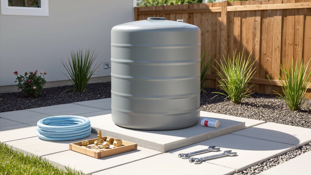
A DIY water storage tank can supply household needs, irrigation, firefighting reserve, or emergency backup depending on size and connection options.
Properly built tanks typically range from a few hundred to several thousand gallons, and with corrosion-resistant materials, quality seals, and routine maintenance can deliver decades of leak-free service.
The build combines site preparation, a stable base, a watertight shell with fittings and vents, and simple testing and treatment to guarantee reliable performance.
What a DIY water storage tank can do and typical use-cases
Several practical needs are met by a DIY water storage tank, from emergency supply during outages to seasonal irrigation and rainwater harvesting for landscape use.
Homeowners, gardeners, and small farms use tanks for potable backup, livestock watering, fire suppression reserve, and graywater buffering.
The guide on how to build a water storage tank outlines adaptable designs for gravity feed, pump-assisted delivery, and modular expansion.
Expected capacity, lifespan, and performance for durable, leak-free results
Capacity, lifespan, and performance are determined by design choices, materials, installation quality, and maintenance regimes.
A well-sized, corrosion-resistant tank with proper foundations and seals typically delivers decades of service; expected capacities range from a few hundred liters to many kilolitres.
Routine inspection, timely repairs, and water treatment preserve structural integrity, prevent leaks, and maintain reliable delivery and quality over time.
Quick summary of the entire build in one paragraph
Start by siting, sizing, and selecting materials based on planned volume and water quality. Then prepare a level foundation, assemble or construct the tank (steel, concrete, or polyethylene) with proper seams and corrosion protection.
Fit inlet/outlet plumbing, overflow, vents, and access points. Install seals and supports, connect to supply and drainage systems, commission with cleaning and leak testing, and establish maintenance and treatment routines.
Materials, Tools, and Site Requirements
Selection of an appropriate tank type—concrete, welded steel, polyethylene, or ferrocement—depends on capacity, budget, and planned use.
Necessary materials and specifications, along with essential tools and personal protective equipment, should be listed and matched to the chosen construction method.
Site requirements such as slope, foundation stability, access for installation and maintenance, and compliance with local codes determine final placement and preparations.
Choosing the right tank type (concrete, welded steel, polyethylene, ferrocement)
Evaluating tank materials—concrete, welded steel, polyethylene, and ferrocement—requires weighing durability, cost, maintenance, and the specific site constraints and tools available.
Each option suits different climates, skills, and budgets:
- Concrete: heavy, permanent, high thermal mass.
- Welded steel: strong, prone to corrosion without coating.
- Polyethylene: lightweight, UV-sensitive, easy to install.
- Ferrocement: thin, reinforced, labor-intensive.
Required materials and their specifications
Having chosen the tank type that best fits the site, the next step is to list the specific materials, tools, and site requirements needed to construct and install it.
Required items include quality tank materials, foundation aggregates, sealants and corrosion protection, and fittings and valves.
Visualize:
- Concrete mix, rebar, formwork
- Polyethylene panels or steel sheets
- EPDM liners or cementitious sealant
- Inlet/outlet flanges, overflow, vents
Essential tools and safety equipment
Tools and safety gear form the backbone of a successful water tank build, ensuring tasks proceed efficiently and risks remain controlled.
Essential items include sturdy gloves, eye and hearing protection, respirator, and steel-toe boots. Power and hand tools, measuring instruments, sealant applicators, and scaffolding complement PPE.
Visualize:
- Glove gripping sheet metal
- Goggles against sparks
- Tape measure across flange
- Scaffold steadying workers
Site selection criteria: slope, foundation, access, and local codes
When selecting a site for a water storage tank, attention to slope, foundation stability, access routes, and compliance with local codes determines long-term performance and safety.
Choose level or gently graded ground; guarantee load-bearing soil or engineered pad; provide vehicle and maintenance access; allow drainage away from the base; maintain required setbacks and permit approvals; verify seismic, floodplain, and easement restrictions before construction.
Planning the Tank: Size, Capacity, and Regulations
The planner assesses required capacity by estimating daily household or irrigation demand and adding safety margin for peak use and drought.
Material choice and tank design are evaluated for structural suitability, longevity, and maintenance implications.
Finally, local building codes, permits, water-safety regulations, and a budget-conscious sourcing plan are reviewed to guarantee compliance and cost-effectiveness.
Calculating required capacity based on household or irrigation needs
Sizing a water storage tank begins by quantifying daily demand: list all household or irrigation uses, assign average consumption rates (liters or gallons per activity), and sum them to determine baseline volume needs.
Factor in reserve for dry periods, peak usage multipliers, system losses and fire or emergency requirements.
Adjust for refill frequency, supply reliability and future growth to set final capacity.
Structural considerations by tank material
After determining required capacity, attention shifts to how material choice affects structural design, longevity, and regulatory compliance.
Concrete requires reinforced bases and expansion joints; steel demands corrosion protection, welding quality, and anchoring for wind loads.
Polyethylene needs UV stabilization, thicker walls for large volumes, and supportive foundations to prevent deformation.
Glass-lined or fiberglass tanks require careful joint sealing and impact protection.
Local building codes, permits, and water safety regulations
Because regulations vary considerably by jurisdiction, planning a water storage tank requires early consultation with local building departments and health authorities to confirm zoning restrictions, setback requirements, permit types, and inspection schedules.
The builder should verify potable-water standards, backflow prevention, overflow and drainage mandates, sanitary access, and required materials or coatings.
Documentation, approved plans, and timely inspections guarantee compliance and protect public health.
Budgeting and sourcing cost-effective materials
With regulatory requirements clarified, attention turns to budgeting and sourcing materials that meet code while minimizing cost.
The planner compares material longevity, maintenance, and upfront expense—concrete, steel, plastic liners, and coatings—prioritizing certified, warranty-backed products.
Bulk purchasing, local suppliers, reclaimed components, and competitive quotes reduce costs.
Contingency allocations for unforeseen repairs and permit fees guarantee realistic budgeting and compliance.
Foundation and Base Preparation
The foundation phase begins with careful excavation, accurate leveling, and thorough compaction to create a stable bearing surface.
Next, choices between a reinforced concrete pad or a well-prepared compacted aggregate base are considered, with details on formwork, reinforcement, curing, and load distribution.
Finally, proper site drainage and frost protection measures—such as slopes, perimeter drains, and frost skirts—are specified to prevent settling and freeze-related damage.
Excavation, leveling, and compaction steps
Begin excavation to establish a stable, level footprint for the tank by removing unsuitable soil and reaching firm subgrade.
Verify depth and outline with stakes and string. Scarify and recompact native subgrade in layers, removing organic matter.
Use mechanical compaction equipment to achieve specified density. Check elevations with a level; adjust and recompact until uniform bearing and drainage slope are confirmed.
Designing and pouring a concrete pad or compacted aggregate base
After confirming uniform bearing and the required drainage slope, attention shifts to designing and installing the tank foundation: either a reinforced concrete pad or a properly graded, compacted aggregate base.
Concrete pads require formwork, reinforcement layout, control joints, and vibration to eliminate voids.
Aggregate bases need well-graded material, layered placement, and mechanical compaction to specified densities.
Edge details and load distribution are confirmed.
Drainage and frost protection details
Proper drainage and frost protection are essential to prevent base heave, undermining, and water intrusion that compromise tank stability and seal integrity.
Install a sloped surround, perimeter drains, and gravel trenching to channel water away.
Use frost-resistant grout, insulation boards, or a deeper footing below frost line.
Guarantee positive surface grade, frost-proof access points, and regular inspection to maintain long-term protection.
Step-by-Step Build Process for Common Tank Types
The next section outlines concise, sequential build processes for common tank types, starting with polyethylene/plastic installation and moving through steel assembly, ferrocement layering, and concrete casting.
Each subsection presents key steps, required materials, and typical timeframes.
Readers are guided to compare methods and select the approach suited to site conditions and capacity needs.
Polyethylene/Plastic Tank installation steps
The installation of a polyethylene tank begins with careful site positioning and anchoring to guarantee stability and access.
Key fittings and connections—installed in sequence—include:
- inlet placement for incoming water
- outlet location for distribution
- overflow and vent arrangement
- pipe connections for supply and drainage.
Final steps verify all pipe connections and perform leak testing before commissioning.
Site positioning and anchoring
Site selection and anchoring for polyethylene tanks focus on stability, accessibility, and protection from environmental stressors.
Position on level, compacted ground or concrete pad, clear of trees and flood paths. Secure with manufacturer-recommended straps or anchors resisting uplift and lateral movement.
Allow service access and maintain ventilation space. Ascertain drainage away from the base to prevent undermining and frost heave.
Inlet, outlet, overflow, and vent fitting
Properly positioned and anchored tanks require correct connection of inlets, outlets, overflows, and vents to function reliably.
Install threaded fittings at designated bosses, using tank-compatible gaskets and backing washers.
Position inlet above anticipated high flow entry, outlet at desired drawdown level.
Fit overflow near the top with visible discharge.
Add a vent sized to prevent vacuum or surge, protected with insect screen.
Pipe connections and leak testing
Begin by dry-fitting all pipework and fittings to confirm alignment, thread sizes, and clearances before applying sealant.
Use appropriate thread tape or plumber’s compound on threaded joints and solvent welds or gasketed flanges where specified.
Tighten progressively to avoid distortion.
Pressurize the tank gently for a static leak test, inspect all joints, mark any seepage, depressurize, repair, and retest until watertight.
Steel tank construction and assembly steps
Steel tank construction follows a clear sequence of tasks that move from structural assembly to final service fittings.
Typical stages include:
- Panel layout and assembly
- Sealing seams and choosing welding or bolting methods
- Corrosion protection and exterior/interior coatings
- Installing fittings, valves, and pressure reliefs
Each stage requires specific tools, skilled labor, and inspection to guarantee a watertight, durable installation.
Panel assembly, sealing seams, and welding vs. bolting
As panels are aligned and fitted together, attention turns to creating durable seams and choosing between welding or bolting for final assembly.
Seams require proper gasket placement, sealant bead application, and clamp support during curing.
Welding gives continuous, rigid joints ideal for pressure and permanence; bolting allows disassembly and simpler field work but needs precise torqueing, washers, and periodic inspection to maintain leak-free integrity.
Corrosion protection and coating
Protective coatings and corrosion control are applied immediately after panel assembly to secure long-term integrity of a steel water tank. This process includes surface preparation, selection of compatible primers and topcoats, and specification of application methods and environmental constraints.
Abrasive blasting, solvent cleaning, and rust conversion guarantee adhesion. Epoxy primers and polyurethane or acrylic topcoats resist water and UV.
Inspection and touch-up protocols prevent early failure.
Installing fittings and pressure reliefs
Begin installation of fittings and pressure reliefs after coatings have cured and inspection confirms sound surfaces.
Select corrosion-resistant fittings sized per design; use proper flanges, gaskets, and PTFE tape.
Drill accurately, deburr edges, and apply sealant.
Mount pressure relief valves with accessible orientation, test setpoints, and secure drains.
Perform pressure and leak tests, document torque values, and verify operation before commissioning.
Ferrocement tank construction steps
Ferrocement tanks are built by assembling a sturdy rebar/mesh framework and setting formwork to define the shell.
Typical workflow follows a clear sequence:
- Fabricate and secure rebar and wire mesh with shuttering
- Apply and compact cement mortar in layers with a timed curing schedule
- Inspect and repeat coatings as needed
- Finish with waterproofing and smooth internal surface treatments.
Rebar/mesh framework and shuttering
The rebar and mesh framework, together with temporary shuttering, provides the structural skeleton and formwork necessary for a durable ferrocement tank.
Careful layout, secure ties, and accurately profiled shutters guarantee uniform mortar cover and the designed tank shape.
Workers assemble steel reinforcement grids, overlap and tie wires at specified spacing, install radial and circumferential supports, then fix removable shutter panels to hold geometry during finishing.
Cement mortar application and curing schedule
Apply cement mortar in controlled layers, ensuring each coat bonds to the steel mesh and previous layer while maintaining the specified cover thickness.
Use a dense, workable mix and compact each layer to eliminate voids.
Allow initial set before subsequent coats, typically 24–48 hours.
Maintain moist curing for at least seven days, extending to 28 days for full strength, protecting surfaces from rapid drying.
Waterproofing and internal finishing
Several critical steps guarantee the tank’s interior remains watertight and durable: surface preparation, selection and application of waterproofing systems, and final finishing to provide smooth, sanitary surfaces.
After curing, inspect and repair microcracks, clean surfaces, and apply bonded cementitious or polymer-modified coatings in specified thicknesses.
Finish with a smooth trowel coat or epoxy lining, ensuring joints and penetrations receive extra reinforcement and sealant.
Concrete tank casting steps
Concrete tank casting requires careful sequencing to guarantee strength, watertightness, and durability.
Key considerations include:
- Formwork design and reinforcement detailing
- Controlled pouring and curing with proper joint treatment
- Application of waterproofing membranes and compatible sealants
- Inspection and repair of defects before backfill
Each step is planned to minimize cracking and leaks and to meet structural requirements.
Formwork design and reinforcement detailing
Begin by laying out a clear formwork scheme and a reinforcement plan that match the tank’s geometry, loading conditions, and construction sequence.
Specify panel types, bracing, tie locations, and access points.
Detail rebar sizes, spacing, lap lengths, anchorage, and corrosion protection for walls, base, and joints.
Include embedments, openings, and tolerances to guarantee alignment and structural integrity during casting.
Pouring, curing, and joint treatment
Pour the mix in continuous, controlled lifts to prevent cold joints and guarantee full consolidation against formwork and reinforcement; use mechanical vibration adjacent to rebar while monitoring slump and temperature to maintain workability.
After casting, cure promptly with wet curing or curing compound for minimum seven days to develop strength.
Treat construction and expansion joints with routed cleaning, compressible fillers, and bonded sealant-compatible backer rod for durable, watertight interfaces.
Waterproofing membranes and sealants
A properly selected and applied waterproofing system is essential to prevent infiltration and extend the service life of a cast concrete water tank.
Membranes—bituminous, PVC, or liquid-applied polyurethane—must adhere to cured concrete and accommodate movement.
Sealants for joints and penetrations should be compatible, UV-resistant, and applied per manufacturer cure times.
Regular inspection and maintenance guarantee long-term watertight performance.
Plumbing, Filtration, and Overflow Systems
The section addresses the layout and sizing of inlet, outlet, and circulation piping to guarantee proper flow and turnover.
It covers placement and capacity of overflow and emergency drains, plus basic filtration and first‑flush devices for both potable and non‑potable applications.
Guidance on installing access hatches, ladders, and inspection ports completes the review of operational and maintenance considerations.
Designing inlet, outlet, and circulation piping
Begin by mapping inlet, outlet, and circulation piping to validate efficient flow, prevent contamination, and accommodate maintenance access.
Specify pipe diameters, flow velocities, and materials compatible with stored water.
Position inlet near top with diffusion to avoid disturbance; outlet near bottom with sediment draw-off.
Include circulation loop and isolation valves for filtration, cleaning, and winterization.
Confirm accessible unions and pressure-rated fittings.
Sizing and placing overflow and emergency drains
Following inlet, outlet, and circulation layout, attention shifts to sizing and locating overflow and emergency drains to protect tank integrity and water quality.
Calculate overflow capacity to handle maximum inflow (including storm or pump failure) and size drains accordingly.
Place overflows near the roofline and emergency drains at low points with independent piping to safe discharge.
Include screened vents and access for inspection and maintenance.
Basic filtration and first-flush devices for potable and non-potable use
Several simple components can markedly improve water quality before storage: coarse screens and sediment traps to remove debris, cartridge or media filters for finer particulates, and first-flush diverters to exclude the initial contaminated runoff.
For potable use include certified multi-stage filtration and UV or chlorination post-storage. For non-potable use, simpler sediment and mesh filters suffice.
Regular maintenance and accessible filter housings guarantee consistent performance.
Installing access hatches, ladders, and inspection ports
After filtration and first-flush devices are in place, attention turns to reliable physical access and inspection points for the tank and its plumbing.
Install secure, gasketed hatches sized for human entry or maintenance, non-slip ladders anchored to structural supports, and multiple inspection ports for sampling and camera checks.
Position ports near inlets, outlets, and overflow lines; guarantee watertight seals and lockable closures.
Waterproofing, Leak Prevention, and Testing
The section outlines appropriate sealants, coatings, and liners selected for common tank materials and configurations.
It then explains methods for sealing joints and penetrations, procedures for pressure and water-fill testing, and techniques to detect and repair typical leaks.
Practical guidance and checklists are provided to verify watertight performance before commissioning.
Best sealants, coatings, and liners by tank type
Different tank materials and uses demand specific approaches to sealing and lining to guarantee long-term waterproofing and rapid leak detection.
Concrete favors cementitious crystalline additives and epoxy or polyurethane coatings; steel needs corrosion-resistant epoxy, zinc primers, and flexible polyurethane topcoats.
Plastic tanks use compatible solvent-free sealants and food-grade liners.
Bentonite or geomembrane liners suit earthen pits.
Selection prioritizes compatibility, UV resistance, and tested potable-water safety.
Joint and penetration sealing techniques
Following appropriate sealants and liners for each tank material, attention turns to joints and penetrations, where the majority of field leaks originate.
Proper techniques include cleaning mating surfaces, using compatible backing ropes, applying continuous bead sealant, and embedding flexible flashing at openings.
Bolted penetrations require gasketed washers and torque control.
Final steps: smooth tooling, cure per manufacturer instructions, and protect seals from mechanical damage.
Pressure and water-fill leak testing procedures
Begin by verifying that all joints, penetrations, and coatings have cured and been inspected. Pressure and water-fill tests should then be conducted methodically to confirm tank integrity under realistic conditions.
Apply controlled pneumatic pressure within safe limits, monitor gauges for hold time and pressure decay, then perform a static water-fill while observing seams and fittings for seepage.
Record results and compare to acceptance criteria.
How to detect and repair common leaks
Inspectors should routinely locate leaks by combining visual examination with targeted tests: surface inspections identify obvious cracks, delamination, or coating failures, while localized water or dye tests, moisture meters, and infrared scans reveal hidden seepage and saturation behind linings.
Repair prioritizes source control: clean and dry, grind edges, apply compatible patching mortar or epoxy, recoat with waterproof membrane, and retest under pressure.
Structural Durability and Corrosion Resistance
Attention to long-term structural durability and corrosion resistance guarantees tank integrity and water quality.
Discussion covers protective coatings, cathodic protection and sacrificial anodes, plus reinforcement methods to control cracking and settlement.
For above-ground tanks, UV-resistant finishes and weatherproofing details are examined to prevent material degradation.
Protective coatings, cathodic protection, and sacrificial anodes
Effective corrosion control combines protective coatings, cathodic protection systems, and sacrificial anodes to extend a water tank’s service life and reduce maintenance.
Coatings (epoxy, polyurethane) isolate metal from water and oxygen.
Impressed current or galvanic cathodic protection prevents anodic metal loss.
Sacrificial anodes (zinc, magnesium) corrode preferentially.
Regular inspection, coating touch-ups, and anode replacement guarantee continued corrosion control and leak prevention.
Reinforcement strategies to prevent cracking and settlement
Because ground movement, thermal cycling, and hydrostatic loads concentrate stresses in critical areas, reinforcement strategies must be engineered to control cracking and minimize settlement, preserving structural integrity and corrosion resistance.
Use rebar grids, fiber reinforcement, and dowels at joints and base connections; design thicker edge beams and base slabs; incorporate settlement joints, proper compaction, and load-transfer mats to distribute loads and limit differential movement.
UV protection and weatherproofing for above-ground tanks
Above-ground water storage tanks require deliberate UV protection and weatherproofing to preserve coatings, prevent material degradation, and maintain watertightness over their service life.
Suitable measures include UV-resistant paints, elastomeric coatings, and reflective topcoats. Sealants and flashing protect seams and fittings.
Regular inspections, touch-up maintenance, and drainage management reduce standing water and thermal cycling, extending structural integrity and corrosion resistance.
Maintenance, Inspection, and Safe Operation
Routine maintenance and inspection guarantee the tank remains safe, durable, and free of contamination.
A clear checklist should guide visual checks, structural assessments, and scheduled cleaning, desludging, and disinfection.
Seasonal measures such as winterizing to prevent freeze/thaw damage and continuous water-quality monitoring complete a practical safe-operation plan.
Regular inspection checklist
A concise, regular inspection checklist guarantees the tank remains watertight, safe, and fully operational by identifying wear, contamination, and system failures before they escalate.
Inspectors should verify structural integrity, seams, and supports; check inlet/outlet fittings and valves for leaks; monitor overflow and venting; and confirm instrumentation and access hatch seals.
Recommended steps:
- Visual exterior and foundation check
- Internal wall and seam inspection
- Fitting and valve operation test
- Vent, gauge, and hatch seal assessment
Cleaning, desludging, and disinfecting procedures
Begin by emptying and isolating the tank to create a safe workspace.
Remove sediment mechanically with shovels or suction, flushing deposits to drain.
Scrub interior surfaces with non-toxic brushes and approved cleaners, then rinse thoroughly.
Disinfect using measured chlorine solution or approved biocide, contact time per guidelines, then flush until residuals are safe.
Document procedures, disposal, and water quality verification before return to service.
Winterizing and protecting from freeze/thaw damage
After cleaning and disinfection are complete and the tank is verified safe for maintenance access, attention shifts to measures that prevent freeze/thaw damage during cold weather.
Insulate exposed pipes and shell, install heat tracing or thermostatic heaters where necessary, maintain a minimal circulating flow or storage level to avoid ice formation, seal vents against drafts, and inspect seals and supports regularly for cracking or displacement.
Monitoring water quality and avoiding contamination
How should water quality be monitored to prevent contamination and protect downstream users?
Regular testing for turbidity, pH, microbial indicators, and residual disinfectant is mandated.
Inspect inlets, vents, screens, and seals for breaches; maintain records and remedial actions.
Implement routine flushing, disinfection, and source protection.
Train operators on cross‑connection control and response to contamination events to guarantee safe distribution.
Common Mistakes, Troubleshooting, and How to Avoid Failures
Common installation errors such as improper joint sealing, incorrect foundation leveling, and poor material selection are primary causes of leaks and structural failures.
A concise troubleshooting guide addresses frequent issues—identifying leak sources, diagnosing odors from contamination or stagnation, and resolving low flow due to blockage or pump problems.
Guidance should also specify clear thresholds for escalating to a professional versus performing safe DIY fixes.
Top installation mistakes that cause leaks or failures
Installers frequently encounter a narrow set of preventable errors that lead to tank leaks, structural failures, or premature wear.
Common installation mistakes include:
- Poor foundation—uneven base causing stress points and cracking.
- Improper joint sealing—incorrect sealant or technique leading to seepage.
- Misaligned fittings—forced connections that warp threads or gaskets.
- Inadequate anchoring—tank movement from wind or hydrostatic pressure causing fatigue.
Troubleshooting guide for frequent problems (leaks, odors, low flow)
Addressing leaks, odors, and low flow requires a systematic diagnostic approach that isolates source, cause, and severity before repairs are attempted.
Inspect seams, fittings, and foundation for visible breaches; test water clarity, taste, and residual chlorine to identify contamination; measure inlet/outlet pressures and screen filters for blockages.
Prioritize sealing, replacing faulty components, cleaning biofilms, and flushing lines; document findings and verify repairs by retesting.
When to call a professional vs. DIY fixes
After diagnosing leaks, odors, or low flow, the next decision is whether the repair can be handled safely by an owner or requires a professional.
Minor tasks—sealant reapplication, filter changes, simple valve replacements—suit competent DIYers.
Complex issues—structural cracks, contamination, pump or plumbing system failure, electrical work, or inaccessible repairs—require licensed technicians.
Prioritize safety, code compliance, and documented warranties when deciding.
Cost Estimates, Timeframe, and Material Comparisons
Typical cost ranges for concrete, steel, plastic, and fiberglass tanks are summarized to allow direct comparison of upfront expenses and per-unit capacity.
Estimated build times and labor needs for prefabricated versus site-built tanks are outlined to set realistic project schedules and workforce planning.
Expected longevity, maintenance cycles, and lifecycle costs of each material are compared to inform long-term selection.
Typical cost ranges for each tank type
Cost varies widely by tank type, capacity, material, and installation complexity; small polyethylene barrels can cost under $200, while large steel or concrete tanks for household or farm use typically range from $1,000 to $20,000 or more depending on size and site work. Typical ranges:
| Type | Capacity | Typical Cost |
|---|---|---|
| Polyethylene | 50–500 gal | $50–$800 |
| Steel | 500–10,000 gal | $1,000–$15,000 |
| Concrete | 1,000–50,000 gal | $2,000–$25,000 |
| Bladder | 100–5,000 gal | $200–$5,000 |
Build time estimates and labor considerations
How long will construction take, and who will do the work, depend largely on tank type, size, site preparation needs, and whether professionals are hired or the owner performs labor; small polyethylene or bladder tanks can be installed in a few hours to a day with minimal tools.
Steel tanks often require several days to a couple of weeks for assembly and anchoring, and concrete tanks can take weeks to months when including formwork, curing, and any excavation or backfill.
Labor skills affect schedule and cost; permit inspections, specialized equipment, and team size influence timelines.
Longevity and lifecycle comparison of materials
After timelines and labor inputs are established, material choice becomes the dominant factor determining a tank’s service life, maintenance cadence, and lifecycle cost. The guide compares common materials: concrete offers multi-decade durability with higher upfront cost; steel requires coatings and periodic maintenance; polyethylene is low-cost, UV-sensitive but easy to replace. Lifecycle costs reflect durability, repair frequency, and disposal.
| Material | Typical Life | Notes |
|---|---|---|
| Concrete | 50+ years | High initial cost |
| Steel | 20–40 years | Coatings needed |
| Polyethylene | 10–25 years | Low cost, UV limits |
Examples, Use Cases, and Scalable Designs
The section presents concrete examples and practical layouts to illustrate how different scales address distinct needs.
A compact household rainwater harvesting tank is shown with a concise parts list, while a medium farm irrigation installation includes a layout and flow considerations.
Attention is then given to modular, expandable systems that allow capacity and distribution to grow with demand.
Small household rainwater harvesting tank example with parts list
A compact example of a household rainwater harvesting tank outlines a 1,000–2,500 liter setup suitable for garden irrigation and non-potable indoor uses, listing essential components, estimated capacities, and simple installation notes.
Components:
- tank (poly or fiberglass)
- screened gutter diverter
- first-flush device
- sediment filter
- inline ball valve
- overflow
- pump (submersible/pressure)
- hose fittings
- foundation pad.
Estimated yield and installation tips included.
Medium farm irrigation tank example and layout
Moving from small household systems to medium-scale farm irrigation, this example outlines a 10,000–50,000 liter tank layout suited to irrigating orchards, market gardens, or fodder plots.
A reinforced concrete or polyethylene tank sits on compacted base with overflow, inlet filter, and inspection hatch.
A gravity-fed manifold or diesel/electric pump supplies drip lines; include shutoffs, pressure regulator, sediment trap, and access for maintenance.
Modular and expandable systems for growing demand
Many farms benefit from modular water storage that can grow with need, allowing owners to add discrete tanks, inline connectors, and pump modules without redesigning the whole system.
Examples include stacked poly tanks, interlinked bladders, and containerized cisterns.
Use cases span irrigation expansion, emergency reserves, and seasonal buffering.
Scalable designs emphasize standardized fittings, valved isolation, distributed sensors, and incremental pumping capacity.
Final Safety, Legal, and Environmental Considerations
The final section addresses potable water safety and measures such as backflow prevention to protect supply quality.
It also covers environmental responsibilities, including proper disposal or recycling of decommissioned tanks and mitigation of contamination risks.
Required documentation, warranties, and systematic record-keeping for inspections and maintenance are summarized to guarantee legal compliance and traceability.
Ensuring potable water safety and backflow prevention
Any water storage system designed for drinking must meet strict safety and backflow-prevention standards to protect public health and comply with local regulations.
The builder should select NSF/ANSI-certified materials, install approved backflow preventers and air gaps, and maintain accessible sampling points.
Regular chlorination, filtration, inspection, and recordkeeping guarantee potability.
Compliance with permits and local health authority guidance is mandatory.
Environmental impacts and proper disposal of old tanks
Addressing environmental impacts and disposing of old tanks requires careful planning to prevent soil, groundwater, and ecosystem contamination while complying with waste and recycling regulations.
Old tanks should be drained, cleaned of residues, and decontaminated before transport. Materials must be identified for recycling or hazardous waste handling.
Local disposal rules and permits guide removal, minimizing pollution risks and ensuring legal, responsible tank retirement.
Documentation, warranties, and record-keeping for inspections
Proper documentation, clear warranties, and systematic record-keeping form the backbone of a defensible inspection program for water storage tanks, ensuring traceability of work, compliance with regulations, and protection against liability.
Records should include inspection dates, findings, photographs, repair actions, materials used, and contractor details.
Warranties must specify coverage, exclusions, duration, and claim procedures.
Retain records per local legal and insurance requirements.
Conclusion
The guide concludes that careful planning produces reliable capacity, thoughtful material choice guarantees lasting durability, precise foundation work prevents settling, and proper sealing eliminates leaks. By following regulations, documenting dimensions, sourcing quality components, and testing assemblies, users achieve safe storage, efficient maintenance, and predictable performance. Attention to detail reduces risk, routine inspection preserves function, and preparedness for repair secures supply. With these practices, a resilient water tank becomes a practical, long‑term asset.