How to Test a Condensate Pump: Step-by-Step Troubleshooting and Safety Checklist
To effectively test a condensate pump, follow these steps: First, isolate the power supply to ensure safety. Next, add water to the pump to activate the float and observe the discharge and check valve operation. Inspect the reservoir, tubing, and float for any debris or damage. Measure the motor voltage and current against the nameplate specifications, and listen for any unusual noises or vibrations. If necessary, clear any clogs, replace faulty floats or valves, and document your findings. Always wear proper PPE and adhere to lockout/tagout procedures to maintain safety. Additional steps may include detailed measurements, repairs, and criteria for replacement.
How to Test a Condensate Pump Safely and Effectively
Testing a condensate pump is recommended whenever routine maintenance is performed, after system repairs, or if slow drainage or alarms occur, since timely checks prevent overflow and equipment damage.
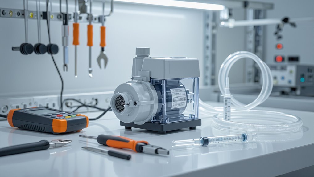
The procedure requires basic tools—screwdrivers, multimeter, and a syringe or turkey baster for adding water—and safety items such as gloves, eye protection, and a noncontact voltage tester.
Clear pre-checks, correct equipment, and adherence to electrical and plumbing safety practices guarantee the test is effective and low-risk.
Quick summary: When and why to test a condensate pump
When should a condensate pump be checked, and what are the reasons to do so?
Routine inspection prevents overflow, water damage, mold, and system shutdowns.
Test after seasonal HVAC startup, unusual noise, slow drainage, or alarm activation.
Technicians follow how to test condensate pump procedures to verify float switch, discharge, and leak protection, ensuring reliable drainage and uninterrupted HVAC operation.
Tools and safety equipment required
Before beginning any checks, the technician assembles the essential tools and safety gear to guarantee accurate testing and personal protection.
Required items include meters, hand tools, and PPE to handle water and electrical hazards.
Typical kit:
- Multimeter and non-contact voltage tester
- Screwdrivers, pliers, tubing wrench
- Wet/dry vacuum and small flashlight
- Gloves, safety glasses, and rubber-soled shoes
Condensate Pump Basics You Need to Know
A condensate pump collects and removes water produced by HVAC and refrigeration systems, typically mounted near the air handler or in a drain pan.
Common types include small electric submersible pumps and pedestal units, each made of a motor, float switch, check valve, and discharge line.
Knowing typical failures—stuck floats, clogged lines, motor burnout, or leaking housings—and their symptoms like continuous running, no discharge, or unusual noise helps prioritize testing and repairs.
What a condensate pump does and where it’s installed
Understands and manages condensate flow, the condensate pump collects and expels water produced by HVAC systems, boilers, and dehumidifiers that cannot drain by gravity.
It prevents backups and moisture damage by moving condensate to distant drains or outdoors.
Typical installations are near equipment, in basements, crawlspaces, rooftops, or mechanical rooms, positioned for short piping runs and accessible for maintenance.
Common condensate pump types and components
Condensate pumps come in several common configurations—submersible, pedestal, and self-contained units—each built around the same basic components: a collection reservoir, a pump mechanism, a float or level sensor, inlet and discharge connections, and often a check valve and electrical controls.
Materials, motor type (sealed or replaceable), mounting style, capacity, and safety features vary to match system size, discharge height, and installation constraints.
Typical failure modes and signs of a malfunctioning pump
When neglected or improperly matched to system demands, condensate pumps commonly fail from clogged reservoirs or inlet screens, seized or burned-out motors, faulty floats or level sensors, cracked housings and seals that leak, and blocked or frozen discharge lines.
These failures produce symptoms such as persistent reservoir overflow, intermittent or no pump cycling, unusual noises, weak or absent discharge flow, and moisture or corrosion around the unit.
- Overflowing reservoir
- Noisy motor grinding
- Intermittent cycling
- Visible leaks and corrosion
Pre-test Safety Checklist
Before testing, the technician verifies power isolation and applies lockout/tagout to prevent accidental energization.
They prepare protective gear and neutralizing materials for handling hot or acidic condensate.
They also check for proper drainage, overflow protection, and any environmental containment requirements.
Power isolation and lockout/tagout steps
Although the pump and its control circuits may appear inactive, verify complete de-energization by isolating the supply at the main disconnect and engaging appropriate lockout/tagout devices; document the isolation points, notify affected personnel, and confirm zero voltage at the motor terminals with a calibrated tester before proceeding.
After isolation, attach durable tags, record responsible persons, secure keys, and re-check controls to guarantee no inadvertent re-energization.
Handling hot or acidic condensate safely
Since condensate can be both scalding and corrosive, personnel must assume all liquid in the system poses a hazard and take protective measures accordingly.
Use chemical-resistant gloves, face shield, apron and boots rated for temperature and pH.
Vent and cool lines before opening.
Neutralize acidic residues with appropriate agent after sampling.
Dispose of waste per facility protocols and document exposures or spills immediately.
Environmental and overflow precautions
Having secured personal protection and neutralized or cooled hazardous condensate, attention shifts to protecting the surrounding environment and preventing system overflows during testing.
Inspect drains, seals, and containment trays for integrity. Place secondary containment under discharge points. Verify float switches and alarm functionality. Keep spill kits and neutralizers ready.
Ascertain waste disposal follows local regulations to avoid contamination or fines.
Visual and Preliminary Inspections
A thorough visual and preliminary inspection begins with examining the pump exterior, tubing, and fittings for cracks, corrosion, or loose connections.
The condensate reservoir and float mechanism should be checked for proper movement, debris, and signs of leakage.
Finally, check valves, vents, and drain lines must be verified for proper orientation, obstructions, and secure seating.
Inspecting the pump exterior, tubing, and fittings
Begin by visually evaluating the condensate pump’s exterior, tubing, and fittings for obvious signs of damage, leaks, or corrosion. This preliminary inspection establishes whether further testing is warranted and identifies immediate safety concerns.
Note cracks, brittle or soft hoses, loose clamps, mineral buildup, and seepage at joints.
Verify secure electrical conduit entry and unobstructed venting.
Record findings for next steps.
Checking the condensate reservoir and float mechanism
Inspect the condensate reservoir and float mechanism for cleanliness, proper operation, and signs of wear that could impede drainage.
The reservoir should be free of sludge, algae, and mineral buildup. Confirm the float moves smoothly without sticking and that its travel switches engage reliably.
Check for cracks, loose mounts, or corrosion and note any debris that could obstruct float travel or trigger false shutoffs.
Verifying check valves, vents, and drain lines
Verify that check valves, vents, and drain lines are intact, unobstructed, and correctly oriented before any operational testing begins.
Inspect for cracks, corrosion, loose fittings, and proper flow direction markings.
Make certain vents are free of debris and positioned to prevent siphoning or backflow.
Confirm drain lines slope toward discharge and lack kinks.
Replace damaged components and reseal joints as needed.
Step-by-Step Functional Test Procedure
The technician proceeds with a focused functional check to confirm that electrical connections, float mechanisms, and discharge performance operate correctly. A clear sequence guides the test:
- Restore power and verify electrical connections.
- Manually activate the float and observe response.
- Simulate activation by adding water to the reservoir (add enough to raise the float to its switch point, typically 1–2 inches below the overflow).
- Listen for pump operation and verify discharge while measuring voltage, current, and flow rate against expected values.
Measurements are compared to manufacturer specifications to determine pass/fail.
Step 1 Restore power and verify electrical connections
Reapply power to the condensate pump circuit and confirm all wiring and terminals are secure before energizing the unit.
A qualified technician checks breaker/fuse status, verifies correct voltage at the pump, inspects for frayed conductors, tightens loose terminals, and confirms grounding integrity.
Verify control circuit connections (float switch, safety switches) are properly seated and circuit protection ratings match manufacturer specifications before proceeding.
Step 2 Manual float activation and observation
Activate the float manually to observe pump response and confirm the control sequence operates as designed.
The technician lifts the float to the run position, watches for motor engagement, listens for unusual noises, and notes relay or indicator activity.
Release the float to verify pump shutoff and float return.
Record response times, irregularities, and any mechanical sticking for follow-up maintenance.
Step 3 Simulated activation with water (how much and where to add)
Proceed to introduce water into the condensate basin to simulate normal operating conditions and verify automatic pump activation.
Pour clean water slowly near the float, adding roughly 1–2 inches (25–50 mm) initially, then continue until the float reaches its switch point.
Use a measured container, avoid splashing electronics, and note activation threshold.
Repeat once to confirm consistent automatic response.
Step 4 Listen and observe pump operation and discharge
Step 4 requires careful listening and visual checks as the pump runs and the discharge line carries condensate.
The technician notes sound consistency, unusual vibration, squeals, or grinding.
Observe for steady, uninterrupted flow, proper check valve action, and leaks at fittings or hoses.
Confirm the pump cycles smoothly without hunting or rapid on/off events.
Record any anomalies for corrective action.
Step 5 Measure voltage, current, and flow rate (what readings are normal)
With the pump running and any irregular noises or leaks noted, measurements of electrical and hydraulic performance are taken to verify proper operation.
Voltage at motor terminals should match nameplate within ±5%. Running current should be near rated amperage; significant deviation indicates mechanical or electrical issues.
Flow rate is compared to manufacturer specifications; reduced flow suggests blockage, worn impeller, or air entrainment.
Step 6 Check automatic shutoff and safety switches
Verify the condensate pump’s automatic shutoff and any safety interlocks by simulating normal and fault conditions to confirm reliable activation and deactivation.
Inspect float switches, pressure sensors, and float stems for free movement and corrosion.
Trigger high-level and low-level events to observe response times and alarm operation.
Record trip thresholds, reset behavior, and any inconsistent or delayed actions for repair or replacement.
Step 7 Test check valve and backflow prevention
Having confirmed the automatic shutoff and safety switches, attention shifts to the check valve and backflow prevention devices to guarantee condensate cannot return to the appliance or drain system.
Inspect visually for damage or debris, operate pump while observing one-way flow, and listen for leaks.
Verify valve seals under pressure and confirm backflow preventer orientation and functionality; replace if performance is compromised.
Diagnostic Tests for Common Problems
A set of targeted diagnostic tests helps identify why a condensate pump fails to operate, moves water inadequately, cycles abnormally, makes noise, or shows signs of leakage and corrosion. Technicians should follow step-by-step checks for power, impeller and discharge integrity, float/sensor operation, pressure and cycle timing, vibration sources, and visible chemical or rust damage. The table below outlines quick problem indicators, likely causes, and the first actions to take.
| Problem Indicator | Likely Cause | First Action |
|---|---|---|
| No power / pump won’t run | Blown fuse, tripped breaker, bad wiring | Check power, reset breaker, test with multimeter |
| Pump runs but won’t pump out water | Clogged discharge, seized impeller, blocked check valve | Clear discharge, inspect impeller, remove blockage |
| Pump cycles too frequently / noises / leakage | Faulty float/sensor, air in line, worn bearings, corrosion | Inspect float, purge air, check bearings, examine for leaks |
No power or pump won’t run diagnostic steps
When a condensate pump shows no power or fails to run, technicians should begin with a systematic, safety-first approach that isolates electrical and control issues before inspecting mechanical components.
Verify mains power, plug, and breaker; test outlet with a known-good device.
Inspect fuse, inline switch, float or pressure switch continuity, and thermostat or control board outputs.
Replace faulty electrical parts; document findings.
Pump runs but won’t pump out water diagnostic steps
Start by isolating the symptom: the motor runs but the pump fails to move water.
Inspect inlet for clogs, debris, or collapsed tubing.
Check impeller for damage, jamming, or corrosion.
Verify discharge line clearance and absence of airlocks; lift and prime if applicable.
Confirm check valve orientation and operation.
Test head pressure against pump specification and replace worn components accordingly.
Pump cycles too frequently or short-cycles diagnostic steps
Diagnose short-cycling by confirming the pump is actually turning on and off more often than the expected fill/drain cycle.
Inspect float switch for debris, kinked wiring, or improper travel.
Verify reservoir volume and inlet leaks that refill tank prematurely.
Check check valve and discharge line for backflow.
Test control board or relay for rapid switching.
Record cycle timing for comparison to specifications.
Pump makes unusual noises or vibrates diagnostic steps
Investigate unusual noises or vibration by isolating mechanical and flow-related causes and proceeding from simple to complex checks.
Verify pump mounting and rubber isolators for looseness or wear.
Inspect impeller for damage, sediment, or foreign objects.
Check motor bearings for play and lubrication.
Confirm discharge tubing is supported and free of kinks.
Run pump and localize noise source before replacing components.
Leakage, corrosion, or chemical damage diagnostic steps
After checking for noise and vibration sources, focus shifts to any signs of leakage, corrosion, or chemical damage that can compromise pump performance and safety.
Inspect fittings, seals, and tank seams for wetness or residue. Smell for chemical odors and test pH of drained condensate.
Examine metallic surfaces for pitting or rust. Replace degraded components, clean deposits, and document findings for maintenance.
When to Repair vs Replace
The decision to repair or replace hinges on whether the issue can be fixed with stepwise repairs—cleaning, replacing seals, or swapping a motor—or whether failure patterns indicate imminent repeat breakdowns.
Clear replacement indicators include cracked housings, seized motors, frequent trips, or obsolete models that lack compatible parts.
Selecting a new pump should factor in capacity and installation fit. Cost comparisons, remaining warranty, and compatibility with the system determine whether repair savings outweigh the long-term value of replacement.
Repairable issues and stepwise repair actions
Assess common condensate pump faults—clogged lines, stuck floats, failed check valves, electrical issues, and worn seals—and categorize which are typically repairable versus those that prompt replacement.
Repairable issues: clear tubing, clean or free float assemblies, replace check valve cartridges, tighten or rewire connectors, and replace seals or motors when parts available.
Prioritize documented stepwise checks, part compatibility, and cost-effectiveness before proceeding.
Replacement indicators and selecting a new pump
Several clear indicators signal when a condensate pump should be replaced rather than repaired: frequent recurring failures despite repairs, visible corrosion or cracked housing, motor overheating or excessive vibration, inability to maintain prime, and lack of available replacement parts for the specific model.
- Rusted tank with leaks
- Burnt or noisy motor
- Repeated float switch failures
- Intermittent priming and flow loss
Cost, warranty, and compatibility considerations
When repair costs approach or exceed the price of a new condensate pump, owners should weigh upfront expenditure against long-term reliability, warranty coverage, and parts compatibility. Decision factors include labor, expected remaining life, and availability of OEM parts. A clear cost–benefit analysis and warranty comparison guide whether to repair.
| Factor | Consideration |
|---|---|
| Repair cost | Labor + parts |
| New pump price | Unit + installation |
| Warranty | Duration & coverage |
| Compatibility | OEM vs aftermarket |
| Life expectancy | Remaining years |
Post-test Actions and Preventive Maintenance
After testing, attention turns to cleaning, descaling, and lubrication to restore pump efficiency and prevent corrosion.
A concise maintenance schedule and simple log template should be adopted to track inspections, service actions, and component lifespans.
Seasonal checks and system integration tests guarantee the condensate pump continues to operate reliably within the broader HVAC or boiler setup.
Cleaning, descaling, and lubrication recommendations
Inspect the condensate pump and its components for scale, sludge, and corrosion before performing maintenance; build-up can reduce flow, cause float sticking, and shorten pump life.
Flush the reservoir with dilute vinegar or manufacturer-approved descaler, remove deposits with a soft brush, and rinse thoroughly.
Lubricate motor bearings or pivot points only if specified by the manufacturer, using recommended lubricant sparingly.
Recommended maintenance schedule and log template
Having removed scale, flushed the reservoir, and addressed lubrication needs, the next step is establishing a clear maintenance schedule and log to preserve pump performance and prevent recurrence of issues.
The schedule lists tasks, frequencies, responsible person, and notes. Sample log:
- Weekly: check float and alarms.
- Monthly: clean reservoir, test pump run.
- Quarterly: inspect wiring, seals.
- Annually: full service records.
Seasonal considerations and system integration checks
When should seasonal shifts trigger specific condensate pump actions? The technician evaluates temperature, humidity, and HVAC cycling to adjust pump inspection frequency, float sensitivity, and drain-line heating before cold months.
Integrate checks with boiler, air handler, and humidifier maintenance; verify condensate routing, trap integrity, and alarm interfaces.
Document changes and schedule preventive tasks aligned with seasonal load and system upgrades.
Troubleshooting Scenarios and Real-World Examples
The section presents three practical troubleshooting scenarios to illustrate common condensate pump issues.
First, an HVAC unit’s pump overflows during prolonged high humidity, highlighting float switch sensitivity and drain capacity.
Next, a boiler pump fails in cold weather and a commercial rooftop unit shows intermittent operation, each prompting targeted checks of heating, insulation, wiring, and control relays.
Scenario 1 HVAC condensate pump overflowing during high humidity
Because seasonal humidity can push an HVAC system beyond its designed condensate capacity, a condensate pump may begin to overflow even if the pump and float switch appear to function normally.
Inspect drain pan size, condensate line diameter, and airflow restrictions. Verify coil cleanliness and refrigerant charge.
Temporarily increase pump cycle frequency or add secondary drain safety until permanent corrective actions (drain resizing, condensate diversion, or enhanced dehumidification) are implemented.
Scenario 2 Boiler condensate pump failing in cold weather
If temperatures drop below the pump’s rated range, boiler condensate pumps can seize or lose prime, causing system shutdowns and potential flue-gas condensation backups.
Technicians should inspect for frozen or restricted lines, trapped air, damaged check valves, and inadequate insulation.
Recommend heat tracing, proper slope, and replacing brittle tubing or aging pumps.
Verify restart procedures and test under simulated cold conditions.
Scenario 3 Commercial rooftop unit pump intermittent failure
Investigate intermittent rooftop-unit condensate pump failures by systematically isolating electrical, mechanical, and environmental causes that commonly affect commercial installations.
Inspect power connections, control wiring, and float/sensor operation for loose contacts or corrosion.
Check pump motor bearings, impeller condition, and intermittent overheating.
Verify roof drain routing, freeze protection, and vibration-induced pipe movement.
Document findings, perform repeat testing, and replace defective components as needed.
Safety Reminders and Regulatory Compliance
The section outlines key electrical, plumbing, and disposal regulations that apply to condensate pump testing and installation.
It highlights safety practices to prevent shock, water damage, and code violations.
Guidance is provided on when conditions warrant contacting a licensed technician or plumber.
Electrical, plumbing, and disposal regulations to watch for
Because condensate pumps interact with electrical circuits, plumbing systems, and waste streams, adherence to relevant codes and disposal rules is essential to safe, legal operation.
Technicians should follow local electrical codes for wiring and bonding, plumbing codes for condensate discharge and backflow prevention, and environmental rules for acidic condensate disposal or neutralization.
Maintain documentation and permits where required.
When to call a licensed technician or plumber
When should a licensed technician or plumber be contacted?
A licensed professional is required for electrical faults, sealed system breaches, persistent leaks, or suspected backflow and code violations.
Call when diagnostics exceed basic checks, replacement parts are needed, permits may be required, or safety risks (shock, flooding, mold) exist.
Document findings and defer to qualified personnel for repairs and compliance confirmation.
Quick Reference: Condensate Pump Test Checklist
A concise checklist helps technicians confirm a condensate pump’s safe operation and identify faults quickly.
The checklist outlines essential visual and functional checks before, during, and after testing, ensuring safety and reliable diagnosis.
- Inspect reservoir, tubing, and float for debris or damage.
- Verify power, fuse, and wiring integrity.
- Activate pump and confirm discharge flow.
- Test float switch activation and alarm function.
Conclusion
Regular testing of condensate pumps guarantees reliable HVAC performance and prevents water damage. As the adage reminds, “An ounce of prevention is worth a pound of cure,” so routine inspections and prompt corrective actions pay dividends. By following safety checklists, conducting visual and functional tests, and addressing common faults, technicians minimize downtime and extend equipment life. Consistent documentation and adherence to regulations complete a proactive maintenance strategy that keeps systems operating smoothly.