What Is a Charge Pipe? Simple Guide for Turbo Cars & Upgrades
A charge pipe is a crucial component in turbocharged cars that transports compressed air from the turbocharger, through the intercooler, and into the throttle body or intake manifold. It plays a vital role in maintaining pressurized airflow, housing sensor ports, and ensuring secure connections with couplers and clamps. The design, diameter, and material of the charge pipe can significantly influence pressure loss, heat transfer, and boost response. Common issues with charge pipes include hissing sounds, loss of boost, and oily connections. The following sections will cover how to inspect charge pipes, the materials used, fitment considerations, and upgrade options.
What a Charge Pipe Is and Where It Fits in a Turbo System
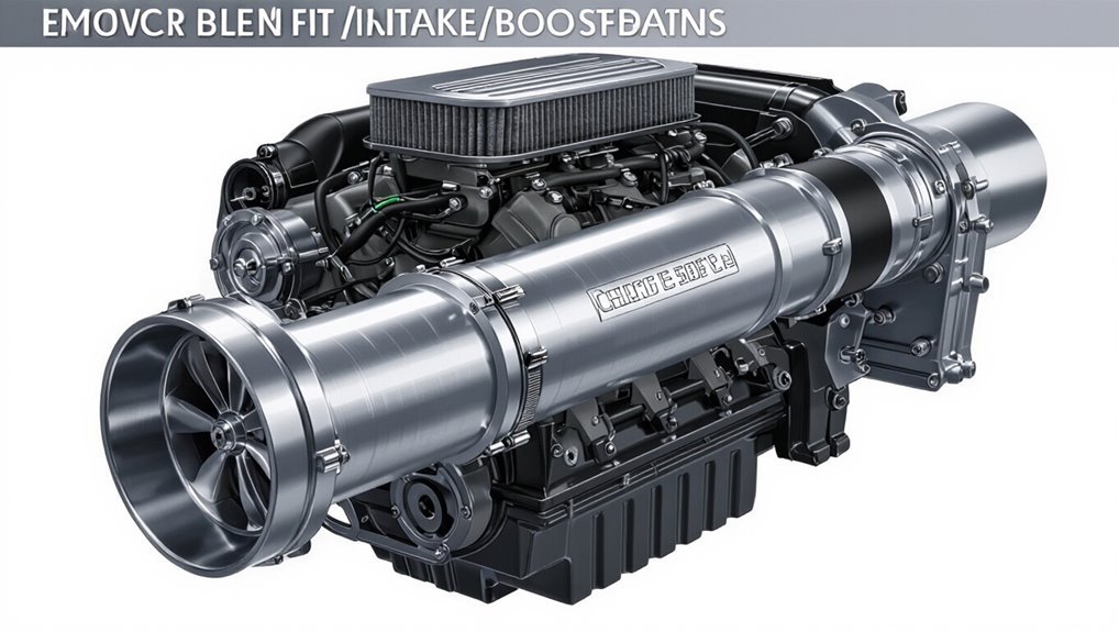
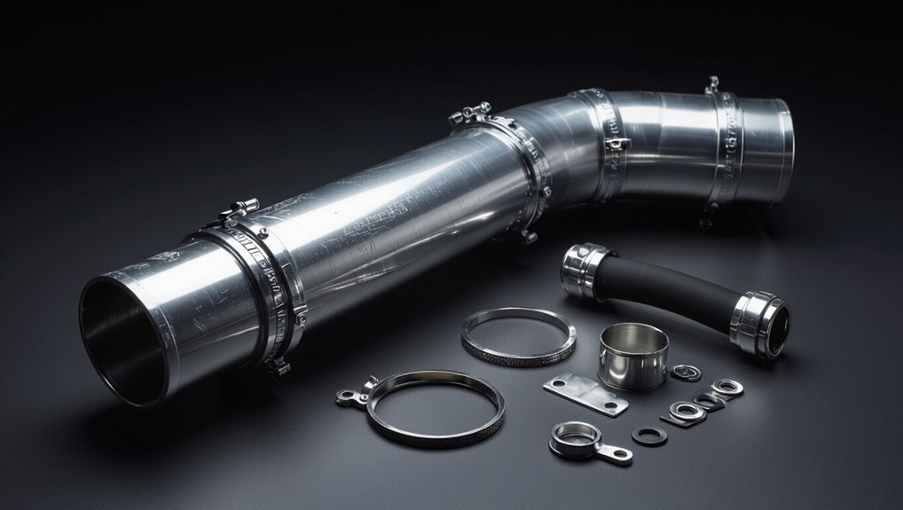
A charge pipe is a rigid conduit that directs compressed air from the turbocharger’s compressor outlet through the intercooler and toward the engine intake, forming the primary pressurized airflow path in a turbo system. It links turbo, intercooler, and throttle body or intake manifold, maintaining sealed routing of boost.
Constructed from aluminium, coated steel, or reinforced silicone, it resists pressure and heat while minimizing flex and leaks. Mounting brackets and couplers secure alignment and absorb vibration.
Proper diameter and routing reduce pressure loss and interference with other components. Replacements often upgrade durability, fitment, or aesthetics without altering basic placement.
How Charge Pipes Work (Airflow & Boost)
In turbocharged systems, the charge pipe channels pressurized air from the compressor outlet through the intercooler and onward to the throttle body, ensuring steady delivery of boost pressure and airflow rates.
It balances pressure pulses, minimizes flow resistance, and maintains ideal velocity for throttle response.
Design, diameter, and smoothness influence pressure drop and transient behavior.
Proper routing avoids heat soak and recirculation.
Connections and clamps prevent leaks that reduce boost and trigger wastegate cycling.
- Smooth bore reduces turbulence and pressure loss.
- Appropriate diameter preserves velocity and peak flow.
- Firm seals prevent boost leaks and lag.
- Routing minimizes heat transfer and bends.
Stock vs Aftermarket Charge Pipes
Comparing stock and aftermarket charge pipes highlights trade-offs between durability, fitment, and performance. Stock pipes prioritize cost, noise suppression, and exact OEM fit; they often suffice for stock power and warranty preservation. Aftermarket pipes aim for increased rigidity, improved flow, and sometimes simplified routing to support higher boost or aggressive tuning. Fitment and warranty implications vary; some require intercooler or mounting changes. Maintenance and leak risk differ: stronger pipes resist blow-off but may transfer vibration. Selection depends on planned power, installation complexity, and budget.
| Feature | Stock | Aftermarket |
|---|---|---|
| Cost | Low | Higher |
| Flow | Adequate | Improved |
Materials and Pros/Cons: Plastic, Aluminum, Silicone
Many charge pipes are made from one of three common materials—plastic, aluminum, or silicone, each offering distinct trade-offs in strength, thermal behavior, and cost.
Plastic is lightweight and inexpensive but can deform under heat and pressure. Aluminum resists heat, is rigid, and suits performance builds though it can transmit heat and dents. Silicone hoses absorb vibration, tolerate thermal cycling, and are flexible, but require reinforcement for high boost and can be pricier. Selection depends on goals: economy, durability, heat management, or flexibility.
- Plastic: cheap, light, less durable
- Aluminum: strong, thermally conductive, rigid
- Silicone: flexible, heat-tolerant, needs reinforcement
- Trade-offs: cost versus performance and reliability
Signs Your Charge Pipe Is Leaking or Failing
A failing charge pipe often announces itself with high-pitched whistling or hissing as pressurized air escapes.
Drivers may notice a steady loss of boost and reduced engine responsiveness when the system cannot hold pressure.
Oil or debris visible around couplers and joints can further indicate a leak or structural failure.
Whistling Or Hissing Noise
How can a high-pitched whistle or steady hiss reveal a failing charge pipe? A sharp or continuous sound often signals pressurized air escaping from a crack, loose clamp, or degraded silicone coupler. These noises change with rpm and throttle, becoming more pronounced under load. Technicians use auditory clues to locate leaks before symptoms escalate.
- Sudden high-frequency whistle near turbo or intercooler junctions.
- Steady hissing during steady throttle indicating small persistent leak.
- Fluctuating pitch with revs pointing to intermittent seal failure.
- Audible change after cold starts suggesting temperature-affected material failure.
Loss Of Boost
Following the audible clues of whistling or hissing, a clear mechanical consequence of a compromised charge pipe is loss of boost pressure.
Reduced acceleration, sluggish throttle response, and lower peak power indicate leaks or disconnections in the intercooler plumbing.
A failing charge pipe often prevents the turbo from maintaining target boost, causing the wastegate or ECU to compensate and triggering limp modes or fault codes.
Boost gauges show inconsistent or capped readings.
Symptoms may appear under load or during spool-up.
Diagnosing requires pressure testing or visual inspection of joints, clamps, and couplers to locate leaks and determine whether repair or replacement is needed.
Visible Oil Or Debris
Where does the oil or grime visible around the charge pipe come from, and what does it reveal about the system’s condition?
Evidence of oil or debris on or near the charge pipe often indicates leaks, blow-by, or filter failures. It signals compromised seals, loose clamps, or cracks allowing pressurized air and oil mist to escape. Contamination can reduce intercooler efficiency and attract soot, degrading sensors and hoses.
Inspection and cleaning reveal leak sources; repairs prevent engine wear and boost loss.
Typical observations include:
- Sooty oil deposits at jointed connections.
- Wet oil trails downstream of clamps.
- Dirt accumulation around cracks.
- Oil in the intercooler sump.
How to Inspect and Pressure-Test a Charge Pipe
A systematic visual inspection checks the charge pipe for cracks, loose clamps, oil residue, and silicone deterioration.
Following visual checks, a controlled pressure test verifies sealing integrity by pressurizing the system and observing pressure hold or leaks at joints.
Clear documentation of findings and any leak locations guides repair or replacement decisions.
Visual Inspection Procedure
How should a charge pipe be inspected and pressure-tested to reliably reveal leaks, cracks, or loose connections? A systematic visual inspection precedes any pressurization: clean surfaces, remove heat shielding, and use good lighting. Look for dents, corrosion, seam separations, and condition of couplers and clamps. Note suspect areas before testing to target verification.
- Check exterior for abrasions, hairline cracks, or oil residue indicating leakage.
- Inspect couplers for hardening, splits, or missing clamp hardware.
- Verify welds and silicone joints for uniform adhesion and no gaps.
- Record findings and mark locations for focused pressure testing.
Pressure Test Steps
Before pressurization begins, the inspector should confirm that all visual findings are documented, fittings are accessible, and appropriate safety gear and pressure-regulating equipment are in place.
The procedure then proceeds by isolating the charge pipe, capping openings, and attaching a calibrated hand pump or compressor with a regulated gauge.
Pressurize to a conservative test pressure (typically 1–2 psi above normal boost), monitor for five minutes, and watch for gauge drop.
Concurrently, spray soapy water on joints or use an ultrasonic leak detector.
If leaks appear, depressurize, repair or replace faulty sections, and repeat until no pressure loss is detected.
When to Upgrade Your Charge Pipe
Under heavy boost or after years of use, a stock charge pipe can develop cracks, leaks, or soft spots that compromise boost stability and engine safety. Inspection and symptoms guide timing for replacement. Visible damage, recurring boost leaks despite clamps and hoses, or sudden loss of power indicate urgent upgrade.
Performance builds that increase boost or introduce higher intake temperatures often warrant stronger plumbing. Preventive replacement is reasonable for high-mileage or track-driven cars to avoid catastrophic failure. Consider upgrades when the factory part shows wear or when reliability under increased load becomes a priority.
- Visible damage or soft spots
- Recurring boost leaks
- Increased boost or tuning
- Track/high-mileage use
Choosing an Aftermarket Charge Pipe (Diameter, Bends, Material)
When selecting an aftermarket charge pipe, prioritize fitment and flow by matching diameter, bend geometry, and material properties to the vehicle’s boost levels and installation space.
Diameter affects airflow and pressure drop: larger pipes suit higher boost but can slow transient response; smaller pipes may restrict peak flow.
Bend geometry influences turbulence and packaging; smooth, mandrel bends preserve flow, tight or multiple bends increase losses.
Material choice balances strength, weight, thermal conductivity, and corrosion resistance: aluminum, stainless steel, and composite options each have trade-offs.
Choose a pipe that maintains required strength at boost pressures while minimizing flow losses and heat soak.
Fitment Basics: Couplers, Sensors, and Layout
After matching diameter, bends, and material to vehicle needs, attention turns to how the charge pipe integrates with the engine bay: couplers, sensor ports, and overall layout determine sealing, serviceability, and sensor accuracy.
Proper silicone or reinforced couplers prevent boost leaks and tolerate flex; hose clamps or T-bolt clamps secure joints. Sensor ports must align with factory locations or use adaptors to preserve MAP and temperature readings. Routing should minimize length and sharp bends to reduce pressure drop and heat soak while allowing access to other components.
- Coupler selection and clamp type
- Sensor port placement and sealing
- Routing for minimal pressure loss
- Clearance and service access
Installation Tips, Costs, Warranty, and Maintenance
The section outlines typical installation time estimates, ranges of warranty coverage limits, and routine inspection tips for charge pipes.
It summarizes expected labor hours for common setups, clarifies what manufacturer and aftermarket warranties usually exclude, and lists key inspection points such as clamp tightness and coupling integrity.
Readers are guided to balance installation cost and warranty terms with a scheduled maintenance checklist.
Installation Time Estimates
For most vehicle models, installing an aftermarket charge pipe typically requires one to three hours of labor for a competent mechanic and two to five hours for an experienced DIYer, depending on access, required disassembly, and whether related components (intercooler, intake, or turbo piping) must be removed or replaced.
Time varies with fitment complexity, need for custom brackets, and hose/clamp replacement.
Preparation reduces elapsed time: gather tools, inspect hoses, and plan jack/engine support.
Allow extra time for troubleshooting boost leaks, sensor reconnections, and intercooler alignment.
- Prep and tools: 15–30 minutes
- Removal of stock piping: 30–90 minutes
- Fitment and adjustments: 30–90 minutes
- Testing and leak check: 15–30 minutes
Warranty Coverage Limits
Understanding warranty coverage limits requires distinguishing between manufacturer, aftermarket vendor, and installer responsibilities, since each can affect whether a charge pipe replacement or related damage is covered.
Warranty terms often specify approved parts, installation methods, and authorized technicians; deviations or modifications can void coverage.
Aftermarket vendors may offer limited warranties covering defects but not consequential engine or turbo damage.
Installers might provide short-term workmanship guarantees separate from parts warranties.
Documentation, receipts, and pre-installation disclosures are essential when filing claims.
Owners should verify combined coverage before purchase and keep records to support warranty claims if failures appear attributable to manufacturing or installation faults.
Routine Inspection Tips
Frequently, owners should inspect charge pipe installations at regular intervals to catch loose clamps, worn couplers, or signs of oil and boost leaks before they escalate. Visual checks, gentle hand tests, and listening for hisses help identify issues early. Keeping records of inspections supports warranty claims and maintenance schedules.
- Check clamps and bracket tightness; torque per spec where available.
- Inspect silicone couplers for cracks, swelling, or delamination.
- Look for oil residue, hose collapse, or hairline cracks indicating boost leaks.
- Verify alignment after driving stress; retighten and replace damaged parts promptly to prevent failures.
Conclusion
A charge pipe acts as the turbo system’s essential artery, reliably channeling pressurized air between components. Like a well-tuned conductor guiding an orchestra, its design and material influence airflow, durability, and boost response. Owners weigh stock plastic’s convenience against aftermarket metal or silicone’s strength, monitoring for leaks, cracks, or poor couplings. When upgrading, correct diameter, bends, and sensor fitment guarantee performance gains, longevity, and safer, more consistent turbo operation.