
How to Use a Compression Fitting: Step-by-Step Guide for DIY Plumbing Success
How to Use a Compression Fitting: A Simple Guide for DIY Plumbing
A compression fitting allows you to join tubing without soldering by utilizing a nut and ferrule to create a secure seal. To effectively use a compression fitting, follow these steps:
- Measure and Cut: Determine the length of tubing required and cut it squarely.
- Deburr: Smooth the cut edges to prevent damage to the fitting.
- Slide Components: Place the nut and ferrule onto the tube.
- Insert the Tube: Push the tube into the fitting until it reaches the shoulder.
- Hand-Tighten: Securely hand-tighten the nut.
- Final Tightening: Use wrenches to make final adjustments while holding the fitting body steady.
After installation, pressure-test the connection using water or soapy air to check for leaks. For additional tips, common issues, and maintenance advice, continue reading.
What a Compression Fitting Is and When to Use One
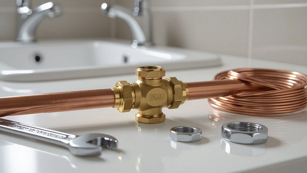
A compression fitting consists of a body, nut, and ferrule or seat and is used to join pipes or tubing without heat. Common materials include brass and plastic, and versions such as flare and compression fittings suit different tubing types and pressure requirements.
They are often chosen for repairs or connections where soldering is impractical, offering a quick, removable joint with limitations in vibration resistance and long-term reliability compared with soldered or push-fit options.
Definition and basic components of a compression fitting
Compression fittings join two lengths of tubing or connect tubing to a fixture by compressing a ferrule or ring onto the pipe with a threaded nut, creating a leak-resistant seal without soldering or adhesives.
A basic compression fitting includes a nut, ferrule (or sleeve), and body. Understanding these parts clarifies how to use a compression fitting and aids correct assembly, tightening, and leak prevention.
Types of compression fittings (brass, plastic, flare vs compression)
After defining the basic parts and function of a compression fitting, it becomes important to recognize the different types available—material choices like brass or plastic, and design variations such as flare versus standard compression—because each type suits different pressures, temperatures, and tube materials.
Brass offers durability and heat resistance; plastic is lightweight and corrosion-resistant.
Flare fittings use cone seals for higher-pressure or soft tubing; compression rings bite the tube.
Common plumbing scenarios for compression fittings
When plumbing runs require a reliable, tool-minimal joint, compression fittings serve as a practical choice for connecting copper, plastic, or soft metal tubing in low- to medium-pressure water lines.
They commonly appear at fixture shutoffs, supply lines to sinks and toilets, appliance connections, and short repairs where soldering is impractical.
Temporary setups, tight spaces, and retrofit jobs also favor their use.
Advantages and limitations compared with soldered and push-fit connections
Although soldered joints and push-fit connectors each have clear strengths, compression fittings occupy a distinct middle ground by offering a solderless, mechanically secure seal that is both reversible and tool-minimal.
They excel where heat is undesirable and access is limited.
Limitations include potential loosening under vibration, lower suitability for small-diameter tubing, and tighter torque tolerances versus permanent soldered joints.
Tools and Materials Needed
A concise list of essential tools sets expectations for any compression fitting job, including wrenches, pipe cutters, and deburring tools.
Recommended materials and spare parts such as extra ferrules, compression nuts, and appropriate tubing should be on hand to avoid interruptions.
Basic safety gear and a prepared workspace—gloves, eye protection, adequate lighting, and a stable surface—ensure the task proceeds safely and efficiently.
Essential tools checklist
Before beginning the installation, gather the specific tools and materials required for compression fittings to guarantee a smooth, safe job.
Essential items focus on accurate cuts, secure connections, and leak testing. Proper selection minimizes rework and damage.
- Tubing cutter, deburring tool, and measuring tape
- Two adjustable wrenches or a wrench set
- Leak detector solution and clean rags
Recommended materials and spare parts to have on hand
Several key materials and spare parts should be kept on hand to complete compression fitting installations efficiently and handle common issues without delay.
Essential consumables and spares minimize downtime and guarantee reliable joints.
- Extra compression nuts, ferrules (brass and plastic), and matching olives.
- Assorted pipe sections and short couplings (copper, PEX).
- Thread sealant, PTFE tape, and replacement shutoff cartridges.
Safety gear and workspace preparation
Proper personal protective equipment and a well-organized work area are essential to safely and efficiently complete compression fitting tasks.
Protective eyewear, gloves, and knee pads reduce injury risk; hearing protection is advised for noisy tools.
Guarantee adequate lighting, ventilation, and a stable work surface.
Keep tools, fittings, and clean rags within reach.
Isolate water supply and display clear trip-hazard control.
Preparing the Pipe and Fitting
Before assembly, the pipe must be measured and cut to the exact length required for the run.
The cut ends should be deburred and cleaned to remove burrs, dirt, and oxidation that could compromise the seal.
The fitting and its ferrule should be inspected for cracks, deformities, or manufacturing defects before installation.
Measuring and cutting pipe to length
Measure the run carefully and mark the pipe where it will be cut, allowing for the compression fitting’s insertion depth and any bends or fittings that affect total length.
Use a pipe cutter or fine-toothed hacksaw held square to guarantee a straight cut. Support the pipe to prevent distortion, rotate the cutter evenly, and re-measure after cutting to confirm correct length before proceeding.
Deburring and cleaning pipe ends
Remove burrs and debris from the cut pipe end to confirm a secure, leak-free seal.
Use a deburring tool or file to remove sharp edges inside and outside the pipe, rotating evenly.
Wipe with a clean cloth or solvent to remove metal shavings, oil, and dirt.
Verify the end is square and smooth so the ferrule seats evenly and the nut threads freely.
Inspecting the fitting and ferrule for defects
The fitting and ferrule should be examined closely for cracks, burrs, deformations, or machining marks that could prevent a proper seal.
Any damage, rough edges, or corrosion warrants replacement.
Verify ferrule bore is concentric and free of residual swarf; confirm threads and compression seat are clean and undamaged.
Reject distorted or mismatched components to avoid leaks and guarantee reliable compression connections.
Step-by-Step Installation Guide
The installation proceeds in a logical sequence: first dry-fit components and confirm alignment, then slide the nut and ferrule onto the pipe with the ferrule oriented correctly.
Next the pipe is inserted to the fitting’s depth markers and the nut is hand-tightened to seat the ferrule.
Finally, wrenches are used to apply the specified torque while monitoring feel for proper compression.
Dry-fitting and alignment check
Dry-fit the tubing and fitting components to verify correct sizes and orientation before any compression is applied.
The installer inspects seating, checks for burrs, and confirms alignment without tightening. This prevents leaks and misalignment.
- Make sure tubing fully seats in the fitting body.
- Verify straight, coaxial alignment with mating parts.
- Confirm clearances for nearby fixtures and access for tools.
Properly sliding the nut and ferrule onto the pipe
After confirming proper seating and alignment, the installer gathers the compression nut and ferrule and prepares the tubing end.
The nut is slid onto the pipe with threads facing the fitting, followed by the ferrule with its tapered edge toward the fitting.
Both components are positioned straight, avoiding rotation against the tubing, and set close to the pipe end for final insertion.
Inserting the pipe into the fitting to depth markers
Insert the tubing straight into the compression fitting until the pipe reaches the molded depth marks or visible shoulder, ensuring the ferrule seats evenly without twisting the tubing.
Confirm alignment by sight and feel; the pipe should stop firmly against the shoulder. If resistance occurs early, withdraw, inspect for burrs or debris, deburr and reinsert.
Maintain axial pressure until ready to tighten.
Hand-tightening the nut and initial seating
With the tubing seated against the shoulder, the installer starts the nut onto the fitting by hand, turning it clockwise until it threads smoothly and the ferrule begins to engage the pipe.
The nut is advanced until finger-tight, ensuring the assembly remains straight and the ferrule compresses evenly.
Excessive force is avoided to prevent misalignment or premature deformation before final tightening.
Final torque technique with wrenches and feel
When the nut is finger-tight and the ferrule sits flush, the installer selects appropriately sized wrenches and positions one on the fitting body and the other on the nut to apply controlled torque; the body wrench holds steady while the nut wrench turns clockwise in short, measured strokes until the specified torque or feel is achieved.
Small increments, pauses, and verification guarantee alignment and secure seating without disturbing the tubing.
How to avoid over-tightening and under-tightening
After final torque is confirmed by measured strokes and steady body support, the installer follows a precise sequence to prevent both over- and under-tightening.
They snug until compression rings seat, then apply prescribed additional quarter-turns or stops per fitting spec.
They verify alignment, inspect ferrule deformation, test for leaks, and back off slightly if distortion appears.
Documented torque values guide repeatable, safe tightness.
Testing the Connection
The installer begins testing the compression fitting by performing pressure checks for both water and air to reveal any leaks.
A systematic visual and tactile inspection follows, noting loose ferrules, misalignment, or moisture.
If a slow leak is found, the procedure calls for re-tightening, re-seating the ferrule, or replacing components as needed before re-testing.
Pressure testing for leaks (water and air)
Pressure testing verifies that a compression fitting holds under operating conditions by applying controlled water or air pressure and observing for drops or visible leaks.
The technician isolates the section, applies pressure gradually to the system’s rated limit, monitors a gauge for steady pressure, and inspects joints.
For air tests, use a soapy solution to reveal bubbles; for water, watch for dampness and pressure loss.
Visual and tactile inspection checklist
Inspectors systematically examine each compression joint using both sight and touch to confirm proper seating, alignment, and absence of defects.
They check for uniform nut compression, ferrule alignment, and surface damage. Light pressure and gentle wiggling reveal movement or roughness; visual cues include gaps, metal shavings, or deformation.
- Verify nut tightness and ferrule position.
- Feel for play or uneven contact.
- Inspect for scratches, cracks, gaps.
What to do if you detect a slow leak
If a slow leak is detected during testing, the inspector should stop live testing and isolate the section to prevent further loss and potential damage.
Then drain and depressurize the isolated segment, dry the joint, and inspect ferrule and nut alignment.
Tighten incrementally or replace damaged components.
After repair, repressurize and retest; document findings and monitor for recurrence.
Common Problems and How to Fix Them
The section outlines typical failures encountered with compression fittings and practical steps to correct them.
Topics include diagnosing and sealing leaks at the nut, techniques for extracting stuck or damaged ferrules, and addressing misaligned or bent pipes.
Criteria for when to repair components versus replace the entire fitting are also provided.
Leaks at the nut: causes and remedies
A weep or steady drip at the compression nut usually indicates a problem with the joint’s seal or assembly rather than a flaw in the tubing itself.
Common causes include loose nuts, misaligned ferrules, scratched or uneven tubing ends, and insufficient nut torque.
Remedies: tighten to spec, realign components, replace damaged ferrules or nuts, clean and deburr tubing, then reassemble and test under pressure.
Stuck or damaged ferrule removal techniques
After addressing leaks at the nut by tightening, realigning, or replacing components, attention turns to ferrules that have seized or been damaged during disassembly.
Use penetrating oil, allow soak time, then twist gently with pliers while protecting the pipe.
If the ferrule remains, cut it off with a rotary tool or hacksaw, smoothing edges and replacing with a new ferrule and nut to guarantee a proper seal.
Dealing with misaligned or bent pipes
When pipes arrive misaligned or slightly bent, compression fittings can fail to seal or strain joints; diagnosing whether the issue is from pipe deformation, improper support, or installation angles guides the corrective steps.
Realign gently using a proper pipe bending tool or replace short damaged sections.
Add or adjust supports, trim ends square, and verify alignment with a straightedge before reassembling to guarantee a reliable seal.
When to replace the fitting versus reusing parts
Decide whether to replace or reuse a compression fitting by inspecting the nut, ferrule, and body for visible damage, corrosion, or deformation that would prevent a proper seal.
Replace if threads are stripped, ferrule is crushed or flattened, or the body shows pitting.
Reuse only undamaged components; always test for leaks after reassembly.
When in doubt, replace the ferrule and nut.
Tips for Long-Lasting, Reliable Compression Joints
Practical guidance for durable compression joints covers working in confined spaces, material compatibility to prevent corrosion and galvanic reactions, and seasonal measures to prevent freezing.
Techniques for maneuvering tools and fittings in tight areas reduce strain on joints and guarantee proper compression.
Selecting compatible metals, using protective coatings or dielectric unions, and insulating exposed pipes help maintain long-term reliability.
Best practices for installation in tight spaces
Working in confined spaces demands careful planning and tool selection to confirm compression fittings are installed correctly and remain leak-free over time.
Use compact, angled wrenches and a tubing cutter sized for the pipe; support the tubing to prevent distortion; mark depth for consistent ferrule placement; tighten incrementally while checking alignment; test under pressure and re-tighten slightly if needed to secure a durable seal.
Preventing corrosion and galvanic reactions
Although compression joints are mechanically simple, their longevity depends heavily on preventing corrosion and galvanic action at metal interfaces.
Use compatible metals, avoid direct contact between dissimilar alloys, and apply dielectric or anti-seize compounds where appropriate.
Confirm clean, dry surfaces before assembly and inspect fittings periodically for signs of electrochemical attack.
Replace compromised components promptly to maintain leak-free, durable connections.
Seasonal and freeze-prevention considerations
Seasonal temperature swings and freezing conditions pose specific risks to compression joints, including seal hardening, frost-induced cracking, and ice expansion that can deform ferrules or loosen connections.
Installers should insulate exposed fittings, slope lines for drainage, and drain outdoor systems before cold spells.
Use cold-rated tubing and seals, employ heat tape where necessary, and inspect joints after seasonal changes to detect and address stress or leaks promptly.
When to Choose Alternative Connection Methods
When selecting a joint type, the article compares compression fittings with soldering, push-fit, and crimp options, highlighting differences in cost, durability, and applicable codes.
It notes that some methods are more economical for DIY work while others offer greater long-term reliability or are required by local regulations.
Situations involving high pressure, concealed piping, or complex repairs are identified as occasions to call a professional plumber.
Comparing compression fittings with soldering, push-fit, and crimp
While compression fittings offer reliable, tool-light connections for many plumbing and instrumentation tasks, alternatives such as soldering, push-fit, and crimp each present distinct trade-offs in permanence, skill level, materials compatibility, and serviceability. Selection depends on access, required permanence, and installer skill.
| Method | Key trait |
|---|---|
| Soldering | Permanent, skilled |
| Push-fit | Fast, removable |
| Crimp | Secure, tool-dependent |
Cost, durability, and code considerations for each method
Because decisions about fittings affect long-term performance and compliance, cost, durability, and local code requirements should guide the choice among soldering, push-fit, crimp, and compression methods.
Soldering is durable and code-accepted but labor-intensive.
Push-fit is costly upfront, quick, and widely approved for repairs.
Crimp offers reliable permanence with tooling costs.
Compression is economical for temporary or accessible joints but may be restricted in concealed installations.
Situations that require a professional plumber
Call a licensed plumber for situations that exceed basic DIY skills or when local codes, safety, or liability are at stake.
Complex mains work, gas lines, water heater connections, pressurized systems, hidden leaks behind walls, or installations requiring permits warrant professional assessment.
A plumber advises on alternative fittings, soldering, or solderless mechanical joints, ensuring code compliance, reliable seals, and warranty-backed workmanship.
Step-by-Step Example Projects
The following examples present two practical projects: installing a compression fitting on a sink supply line and replacing one on an ice maker line.
Each project lists required materials, step-by-step instructions, and a realistic time estimate. Readers can use these guides to compare difficulty and decide whether to proceed or hire a professional.
Installing a compression fitting on a sink supply line (materials, steps, time estimate)
Gather the necessary materials—compression nut and ring (ferrule) sized to the supply line, matching compression-capable shutoff valve or fitting, adjustable wrench, pipe cutter or tubing cutter, emery cloth or fine sandpaper, and a bucket or towel—and allow about 30–60 minutes for removal, preparation, and installation.
Follow these steps:
- Cut and deburr tubing, slide nut and ferrule on.
- Seat ferrule, hand-tighten nut, then wrench-turn 1/4–1/2 turn.
- Test for leaks, tighten slightly if needed, and clean work area.
Replacing a compression fitting on an ice maker line (materials, steps, time estimate)
Replace the compression fitting on an ice maker line using a quarter-inch compression nut and ferrule that match the copper tubing and the appliance’s shutoff valve; allow about 30–60 minutes, and have an adjustable wrench, tubing cutter, emery cloth or fine sandpaper, and a towel or small bucket ready.
The valve is isolated, tubing cut square, ferrule slid on, nut tightened to seat; check for leaks.
- Shut off, drain, cut tubing.
- Clean, assemble ferrule and nut, hand-start.
- Tighten with wrench, test for leaks.
Maintenance and Replacement Schedule
Routine inspections are recommended every 6–12 months, or sooner if vibration, leaks, or visible corrosion appear.
Signs of wear include persistent seepage, deformed ferrules, or loosened nuts indicating loss of seal.
When replacement is required, the old fitting should be depressurized, removed, and a new compression fitting installed following proper alignment and torque specifications.
Routine inspection intervals and signs of wear
When installed and maintained correctly, compression fittings should be inspected at regular intervals to catch wear before leaks develop.
Visual checks every 6–12 months assess corrosion, deforming, or discoloration.
Tightness and moisture should be verified after seasonal temperature changes and vibration events.
Replace fittings showing persistent seepage, cracked ferrules, thread damage, or visible metal fatigue to prevent failure.
How to safely replace an aging compression fitting
After identifying signs of wear during periodic inspections, the procedure for safely replacing an aging compression fitting should follow a clear maintenance and replacement schedule that minimizes risk and downtime.
The technician isolates flow, relieves pressure, documents fitting size and material, and removes nut and ferrule.
Replace with matched components, torque to specification, restore pressure, and verify leak-free operation before returning system to service.
Quick Troubleshooting Flowchart
A concise troubleshooting flowchart guides the user through a stepwise decision process to identify common compression fitting failures.
Each branch directs toward targeted checks and corrective actions—such as re-tightening, replacing ferrules, or inspecting tubing alignment.
The chart emphasizes quick identification and safe resolution to restore proper sealing.
Stepwise decision guide for identifying and resolving common failures
Several clear checkpoints guide the technician through diagnosing and correcting common compression fitting failures.
The flowchart prompts inspection, isolation, and corrective action: verify leak source, check nut and ferrule seating, assess tubing damage.
Follow decisions to tighten, reseat ferrule, replace components, or cut and reprepare tubing.
Record outcome and retest.
- Inspect and isolate
- Verify seating and tightness
- Repair, replace, retest
Conclusion
A compression fitting offers a simple, reliable seal for many household plumbing tasks, yet a lingering theory persists: do torqued ferrules actually cold-weld to pipes over time? While evidence suggests ferrules bite and flow to create a permanent mechanical grip, they do not metallurgically fuse; however, long-term deformation can make removal difficult. This nuance keeps DIYers intrigued: the fitting is both approachable and stubbornly durable, rewarding proper technique while demanding respect during disassembly.