How to Test Igniter on Gas Furnace: Step-by-Step Guide for Safe DIY Diagnostics
To test a gas furnace igniter safely, start by turning off the power and shutting off the gas supply. Inspect the igniter for any visible cracks or soot buildup. For hot surface igniters, use a multimeter to measure resistance; typical readings should be between 40–200 Ω. If you get an infinite or very high reading, the igniter is likely faulty. For spark igniters, check for a visible spark and ensure the transformer and wiring have continuity. Additionally, clean any nearby burners and sensors, document your findings, and if necessary, proceed with further diagnostics.
How to Quickly Determine If Your Gas Furnace Igniter Is Faulty
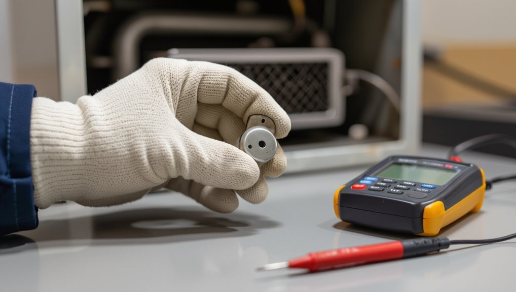
Signs such as repeated clicking without ignition, a visible crack or glow failure on the igniter, and the furnace cycling on safety lockout commonly point to an igniter issue.
Basic checks—visual inspection and confirming power to the ignition circuit—can be performed by a homeowner with the right precautions.
If the igniter is cracked, repeatedly fails after resets, or the homeowner is uncomfortable working with electrical components and gas, a professional should be called.
Common symptoms that indicate an igniter problem
When a gas furnace igniter begins to fail, several clear and repeatable symptoms typically appear that allow a quick diagnosis without special tools.
Indicators include repeated clicking without ignition, delayed or no flame after call for heat, yellow or weak flame, frequent short cycling, and overheating shutoffs.
These signs guide how to test igniter on gas furnace and decide next diagnostic steps.
When you should test the igniter yourself vs. call a pro
Who should attempt an igniter test and when is professional help the safer choice?
A homeowner may perform basic checks—visual inspection, continuity testing with a multimeter, and simple cleaning—if comfortable with electrical safety and gas shutoff.
Call a pro when unsure about wiring, gas components, complex diagnostics, cracked igniters, recurring failures, or when local codes require licensed service.
Safety Precautions Before Testing a Furnace Igniter
Before any work begins, gather appropriate tools and personal protective equipment such as insulated screwdrivers, multimeter, gloves, and safety glasses.
The furnace should be safely shut down and isolated by turning off power at the breaker and closing the gas supply before opening access panels.
Confirm there are no gas odors, use a gas detector if available, and ventilate the area before proceeding.
Tools and protective gear you need
Essential protective gear and basic tools are essential to reduce risk and allow accurate testing of a gas furnace igniter.
Recommended items include safety glasses, heat-resistant gloves, and a dust mask.
Tools: multimeter with temperature probe, insulated screwdrivers, needle-nose pliers, and a flashlight.
Additionally, a non-contact voltage tester and a small wire brush for cleaning contacts improve diagnostics and safety.
How to safely shut down and isolate the furnace
With protective gear and the right tools prepared, the next step is to safely shut down and electrically isolate the furnace to prevent accidental ignition or shock.
Turn off the thermostat, switch the furnace power at the service switch, and shut the circuit breaker.
Close the gas valve only if instructed elsewhere.
Tag the switch and breaker as “DO NOT OPERATE” before proceeding.
Gas safety checks before starting any work
Although the furnace is powered down, the technician must verify that there are no gas leaks and that the fuel supply can be isolated quickly. This includes smelling for odorant, using a calibrated gas detector around joints and fittings, inspecting flexible connectors and valves for damage, and confirming the main gas shutoff operates freely.
Additionally, ventilate the area, evacuate occupants if odor persists, and notify the gas utility before proceeding.
Basic Igniter Types and How They Work
The section outlines the common igniter types found on gas furnaces: hot surface igniters (typically silicon carbide or silicon nitride), spark igniters, and intermittent pilot systems.
It describes how each produces ignition—hot surface elements glowing to light the gas, spark systems arc across electrodes, and intermittent pilots use a timed pilot flame.
Additionally, it notes visible differences such as shape, mounting, and wiring. Compatibility considerations with specific furnace models and control modules are also summarized to guide testing and replacement.
Hot surface igniters (silicon carbide / silicon nitride)
When energized, hot surface igniters (HSIs) heat to incandescent temperatures and ignite the furnace’s gas. They are typically made from silicon carbide or silicon nitride, materials chosen for high-temperature durability and predictable resistance changes.
HSIs operate by resistive heating, require steady voltage, and are fragile. Failure modes include cracking, coating degradation, and altered resistance. Testing uses visual inspection and resistance measurement.
Spark igniters and intermittent pilot systems
Many gas furnaces use spark igniters or intermittent pilot systems as alternatives to hot surface igniters; these devices create a spark or a briefly lit pilot flame to ignite the main burner only when heat is required.
Spark igniters generate high-voltage arcs at electrodes, while intermittent pilots briefly light and sense flame via a thermocouple or flame sensor.
Both conserve energy and reduce continuous pilot hazards.
Visual differences and compatibility with furnaces
A quick visual inspection can distinguish among basic igniter types—hot surface igniters appear as ceramic rods or plates with visible grayish heating elements.
Spark igniters feature small electrode gaps mounted near the burner, and intermittent pilot assemblies include a small pilot burner and associated sensor.
Compatibility depends on furnace model, control board signals, voltage, mounting, and flame-sensor requirements; replace with matching specifications only.
Step-by-Step Procedure to Test a Hot Surface Igniter
A clear, methodical approach guarantees a hot surface igniter is tested safely and accurately.
The technician first locates and inspects the igniter for visible damage, then powers down the furnace and removes the component for bench testing.
Finally, continuity and resistance checks with a multimeter confirm whether the igniter meets expected specifications.
- Locate/access igniter, inspect for cracks or burn marks, and disconnect power.
- Remove igniter safely and perform a continuity test with a multimeter.
- Measure resistance, compare to manufacturer values, and interpret results.
Locate and access the igniter
Begin by turning off power and gas to the furnace at the breaker and shutoff valve to guarantee safety before proceeding.
The technician removes the access panel and locates the burner assembly. The igniter typically mounts near the burners on a porcelain base or metal bracket.
Disconnect the electrical connector, note orientation, and clear surrounding components to gain unobstructed access for testing or replacement.
Visual inspection for cracks, burn marks, or damage
Careful visual inspection is essential before electrical testing, since physical damage often explains igniter failure.
The technician examines the ceramic rod and lead wires for hairline cracks, glazing, soot, or burn discoloration.
Bent or broken elements, melted insulation, and carbon buildup indicate replacement.
Note mounting stability and nearby debris that could cause overheating.
Record visible defects before proceeding to safe removal.
Disconnecting power and removing the igniter safely
Before any work begins, power to the furnace must be completely disconnected and verified off to eliminate shock and ignition risks.
The technician should shut off the breaker and remove the thermostat call. After waiting several minutes for capacitors to discharge, wear gloves and glasses, label and detach the igniter’s connector, then unfasten mounting screws and carefully extract the fragile ceramic element for inspection or replacement.
Performing a continuity test with a multimeter
With the furnace powered off and the igniter removed, the technician uses a digital multimeter set to the resistance (ohms) range to check continuity of the hot surface igniter.
Probes contact the igniter terminals gently; steady connection avoids damage. A stable meter reading or audible beep indicates continuity.
If the meter shows open circuit, the igniter is likely failed and should be replaced.
Measuring resistance and interpreting readings
Begin by setting the multimeter to the appropriate resistance range (typically 0–200 ohms) and ensuring the igniter is disconnected from the furnace wiring; this isolates the component so the reading reflects only the hot surface element.
Measure across the two terminals, record the ohms.
Compare to manufacturer specification (commonly 40–90Ω for many igniters).
Considerably higher, infinite, or zero indicates failure.
Reinstalling the igniter and restart checks
Reconnect the igniter to the furnace wiring, secure it in its mounting bracket, and replace any access panels or flame sensor covers removed during testing.
Restore power and set the thermostat to call for heat.
Observe the ignition sequence: glow, gas valve opening, and flame establishment.
Monitor for unusual sounds, delayed ignition, or repeated retries.
If problems persist, shut off power and consult a technician.
Step-by-Step Procedure to Test a Spark Igniter
The following steps outline how to identify and inspect the spark igniter assembly, verify spark presence safely, and test related electrical components.
First, locate the spark assembly and inspect electrodes and wiring for damage or carbon buildup.
Then test for a visible spark and use a multimeter to check the ignition transformer and wiring; note actions to take if the spark is weak or intermittent.
- Locate and access the spark assembly; inspect electrodes and wiring for damage.
- Observe a controlled, safe spark test; troubleshoot weak or intermittent sparks.
- Use a multimeter to verify transformer output and continuity of ignition wiring.
Locating the spark assembly and access tips
Several furnace models hide the spark assembly behind access panels, burners, or the control compartment, so locating it precisely before testing saves time and prevents damage.
Technicians should power down, remove the minimal panels, and note fastener types. Follow the manufacturer’s layout diagram, observe clearances to heat exchangers and gas lines, and use a flashlight and mirror for confined spaces before proceeding.
Visual inspection of electrodes and wiring
Inspect the electrodes and wiring visually for cracks, carbon buildup, corrosion, loose connections, frayed insulation, or signs of arcing; these defects are the most common causes of intermittent or failed ignition.
Note mounting stability, electrode gap uniformity, and burner shield alignment.
Document any damage and wiring color codes.
Prepare replacement parts or tighten connections before proceeding to electrical testing.
Testing for a visible spark safely
Begin by powering off the furnace and shutting off the gas supply.
Then place a non-conductive work surface and keep a clear escape path—safety precautions must precede any spark testing.
Reassemble access panels partially to observe electrode gap.
Restore power briefly, cycle the thermostat, and watch for a clean, blue-white spark across electrodes.
If absent or weak, stop and de-energize for further inspection.
Using a multimeter to check ignition transformer and wiring
To verify an igniter’s electrical integrity without live sparking, a multimeter can be used to measure the ignition transformer’s secondary resistance, primary continuity, and the wiring between the transformer and electrodes.
Disconnect power, remove connectors, and set the meter to the appropriate ohms/continuity range.
Compare readings to manufacturer specs, inspect for open circuits, shorts to ground, and damaged insulation; document findings.
What to do if the spark is weak or intermittent
After verifying transformer resistance and wiring continuity, attention shifts to diagnosing a weak or intermittent spark at the igniter.
Inspect electrode gap and condition, clean or replace corroded tips, and guarantee secure grounding.
Verify ignition module output under load with proper safety precautions.
If intermittent persists, replace the igniter or module and recheck voltage, timing, and flame sensing for proper operation.
Electrical Tests and Diagnostic Readings
Electrical tests and diagnostic readings give measurable criteria to determine igniter health and wiring faults. Typical resistance ranges, how to recognize open/short/unusual readings, and safe terminal voltage checks are summarized below for quick reference. Technicians should use a multimeter and follow safety procedures when taking these measurements.
| Test Area | Typical Values | Diagnostic Meaning |
|---|---|---|
| Resistance (NTC/glass/ceramic) | 40–200 Ω (common) | Within range = likely good; much higher or infinite = open |
| Circuit condition | 0 Ω (short) to ∞ Ω (open) | 0 = shorted, ∞ = open, intermediate unusual = degraded |
| Voltage at terminals | 0–120 VAC or low-voltage control 24 VAC | No voltage = control/relay issue; wrong voltage = wiring or transformer fault |
Expected resistance ranges for common igniter types
Resistance readings provide a quick, objective check when diagnosing furnace igniters. Different igniter technologies—silicon carbide, silicon nitride, and hot surface igniters (HSI) with varying designs—each have characteristic resistance ranges technicians commonly rely on.
Typical silicon carbide igniters often measure 0.5–3 ohms. Silicon nitride igniters typically range from 10–200 ohms, while modern HSI elements commonly fall between 40–200 ohms, depending on model and manufacturer.
Interpreting open circuits, short circuits, and unusual values
Many diagnostic outcomes fall into three clear categories—open circuit, short circuit, and readings that deviate from expected ranges—and recognizing which applies quickly narrows likely causes and next steps.
An open circuit indicates broken or disconnected igniter/lead. A short suggests internal failure or grounding. Unusual but finite values point to degradation or temperature effects.
Each result guides replacement, repair, or further targeted testing.
Voltage checks at terminals and safe measurement methods
Having determined whether the igniter circuit is open, shorted, or showing abnormal resistance, the next step is to verify proper voltage at the furnace and control terminals to confirm power delivery and safe operation.
Use a multimeter set to appropriate AC/DC range, observe polarity and transformer secondary ratings, measure at gas valve, control board and igniter connector, and follow lockout/tagout and PPE procedures.
Common Causes of Igniter Failure and How to Address Them
Igniter failure most often stems from age and repeated thermal stress that weaken the element over time.
Other common contributors include dirty or clogged burners that impede proper flame establishment and electrical problems such as a faulty control board, bad relays, or damaged wiring.
Incorrect installation or use of incompatible replacement igniters also shortens component life and can prevent reliable ignition.
Age and thermal stress
Age and repeated temperature cycling gradually weaken furnace igniters, causing microfractures in ceramic or silicon elements and degrading electrical contacts.
Over years, thermal expansion and contraction produce stress points that reduce efficiency and lead to intermittent or complete failure.
Visual inspection can reveal hairline cracks or discoloration; resistance checks may show drift from specifications.
Replacement is often the reliable remedy when age-related degradation is evident.
Dirty or clogged burners affecting ignition
When burners accumulate dust, soot, or residue from incomplete combustion, the resulting deposits can block gas ports and alter flame patterns. This prevents reliable contact between the flame and the igniter or pilot sensor.
Technicians recommend inspecting and gently cleaning burners, using appropriate tools and safety precautions, to restore proper gas flow and stable flame geometry. This improves ignition reliability and prevents repeated igniter stress.
Faulty control board, relays, or wiring issues
Cleaning burners can resolve many ignition problems, but electrical faults often mimic or compound those symptoms. A failing control board, sticky relays, or damaged wiring can prevent voltage from reaching the igniter or misread flame signals, causing repeated failure or no ignition at all.
Technicians should visually inspect connections, test relay continuity and output voltages, and replace corroded harnesses or faulty modules to restore reliable ignition.
Improper installation or incompatible replacements
Installations done incorrectly or with incompatible replacement parts are a frequent, yet often overlooked, cause of igniter failure.
Incorrect mounting, wrong voltage or amperage ratings, and improper connector types cause stress, poor contact, or overheating. Technicians should verify part numbers, follow manufacturer torque and clearance specs, and test electrical compatibility.
Replacing with OEM or equivalent components prevents premature failure and guarantees reliable operation.
Troubleshooting: What to Try Before Replacing the Igniter
Before replacing the igniter, basic troubleshooting should address serviceable components that commonly cause startup issues. This includes cleaning burners and flame sensors, checking and tightening or replacing loose electrical connectors, and resetting the furnace control board while noting any error codes.
The technician should distinguish temporary fixes from required permanent repairs to avoid repeat failures.
Cleaning and servicing burners and flame sensors
Inspecting and servicing the burners and flame sensor is a key step in diagnosing ignition problems on a gas furnace.
Burners should be checked for soot, rust, or debris; jets cleaned with a soft brush or compressed air.
The flame sensor requires gentle cleaning with fine emery cloth or alcohol to remove film.
Reassemble and test for reliable ignition and stable flame.
Tightening or replacing loose connectors
Check electrical connections for looseness or corrosion, since poor contacts are a common cause of intermittent ignition that mimic a failing igniter.
Power off before inspecting; tighten screw terminals and re-seat plug connectors.
Replace frayed wires or corroded terminals with matching gauge and proper connectors.
Use dielectric grease on terminals to prevent corrosion.
Verify secure, clean connections before restoring power and testing ignition.
Resetting the furnace control board and error code checks
A simple control-board reset and review of error codes often reveal transient faults or stored diagnostics that mimic igniter failure.
Power down the furnace per manufacturer instructions, wait 30–60 seconds, then restore power.
Consult the control board LED flashes or digital display, note fault codes, and reference the manual.
Clear codes after addressing listed issues, then retest ignition sequence to confirm genuine igniter problems.
Temporary fixes vs. permanent repairs
Differentiate quick, reversible actions from lasting solutions before deciding to replace an igniter: temporary fixes—such as cleaning the igniter and burner area, tightening loose connections, or resetting the control board—can restore operation in many cases, but they do not address underlying wear, corrosion, or intermittent component failure.
Document symptoms and trialed fixes, monitor performance, and schedule permanent replacement when issues recur or diagnostics indicate degraded igniter integrity.
How to Choose and Replace an Igniter Safely
Selecting and replacing an igniter requires confirming matching part numbers and electrical specifications to guarantee compatibility.
A concise, step-by-step replacement checklist—covering power isolation, component removal, correct wiring, and secure mounting—reduces risk and errors.
After installation, standardized post-replacement tests should verify ignition sequence, flame stability, and any fault codes before restoring normal operation.
Matching part numbers and specifications
Compatibility is determined by matching the igniter’s part number, electrical ratings, and physical mounting to the furnace’s original specifications.
Verify model and OEM cross-references, voltage, amperage, resistance, connector type, and bracket dimensions.
Confirm temperature ratings and sensor orientation.
Consult the furnace manual or manufacturer database for approval lists.
Using mismatched components can cause failure, safety hazards, or voided warranties.
Step-by-step replacement checklist
One clear checklist guides the safe selection and replacement of a gas furnace igniter: verify the exact replacement part number and electrical specs, shut off power and gas, allow the system to cool, gather insulated tools and a multimeter, document wiring and mounting positions, remove the old igniter without touching the element, install the new unit with correct orientation and secure connections, restore power and gas, and perform operational and safety tests per manufacturer instructions.
Carefully follow torque, connector seating, and grounding requirements; retain removed hardware and note warranty registration.
Post-replacement tests to confirm proper operation
Begin post-replacement testing by restoring power and gas, then observing a full ignition cycle to verify the igniter lights reliably, the burners establish a stable flame, and the furnace proceeds through normal safety interlocks.
Confirm consistent ignition over several cycles, inspect flame pattern and color, listen for unusual noises, check blower activation and thermostat response, and verify no error codes or gas odors remain.
When to Call a Professional and What to Expect
If the issue involves warranty-covered parts, gas leaks, or uncertainty about electrical connections, a professional should be contacted rather than attempting DIY repairs.
Homeowners are advised to ask technicians about licensing, diagnostic procedures, estimated costs, and whether parts or labor are covered by warranty.
Typical service calls take 30–90 minutes, with diagnostics often costing a modest fee and repairs varying widely depending on parts and complexity.
Safety or warranty reasons to avoid DIY
When should a homeowner stop troubleshooting and call a professional for igniter issues?
A professional is required if gas leaks, electrical hazards, sealed-system components, or manufacturer warranty terms are involved.
Technicians provide certified gas handling, electrical testing, parts replacement, and documentation to preserve warranties.
If uncertainty, recurring failures, or unsafe conditions exist, cease DIY attempts and schedule an HVAC service visit immediately.
Questions to ask an HVAC technician
After deciding that professional help is needed, homeowners benefit from preparing a concise list of questions to guarantee the visit addresses safety, diagnosis, repair options, and costs.
Ask about technician credentials, diagnostic steps, expected cause of igniter failure, required parts, warranty on work and parts, safety procedures during inspection, timeline for repair, and whether temporary fixes are safe until permanent repair.
Typical costs and timeframes for diagnosis and repair
A typical service visit for diagnosing a gas furnace igniter issue costs between $75 and $150 for the service call, with full diagnosis often completed within 30 to 60 minutes.
Repair costs vary: igniter replacement commonly ranges $100–$300 including parts and labor; control board or gas valve repairs may reach $300–$800.
Emergency or weekend service increases rates and turnaround times.
Preventive Maintenance to Prolong Igniter Life
Preventive maintenance helps extend an igniter’s service life and reduce unexpected failures.
A concise routine covers inspection timing, basic homeowner tasks, and seasonal checks to catch issues early.
Recommended steps include:
- Inspect and clean igniter and surrounding area every 6–12 months.
- Perform simple homeowner tasks: power cycling, visual inspection, and keeping vents clear.
- Do seasonal checks before heating season start and after heavy use.
Recommended inspection and cleaning schedule
Monthly visual checks combined with seasonal deep-cleaning create the most effective schedule for extending an igniter’s service life.
Inspect for cracks, soot, corrosion, and loose connections monthly; document findings.
Perform thorough cleaning and component-level inspection each spring and fall, replacing deteriorated parts and verifying flame patterns.
Schedule professional servicing annually to calibrate controls and confirm safe operation, adjusting frequency for heavy-use environments.
Simple homeowner maintenance tasks
With the inspection and seasonal cleaning routine established, homeowners can take a few straightforward steps between service visits to keep an igniter functioning longer.
Regularly replace air filters, keep vents and returns clear, gently vacuum accessible dust around the furnace, avoid touching the igniter, guarantee proper thermostat settings to reduce cycling, and monitor for unusual noises or odors, reporting concerns promptly to a technician.
Seasonal checks to prevent ignition problems
Because seasonal temperature shifts increase furnace workload, homeowners should perform focused checks before heating and cooling seasons to prevent ignition problems.
Inspect and clean burners, vents, and ignition components; replace air filters; verify thermostat function and wiring; check for rust, loose connections, or debris near the igniter.
Schedule professional inspection if unusual noises, odor, or repeated ignition failures occur.
Troubleshooting Flowchart and Quick Reference
A concise troubleshooting flowchart and quick reference summarize common problems, likely causes, and recommended actions for igniter issues. A parallel quick multimeter guide lists what to measure and expected results to confirm igniter condition. The table below provides a compact visual aid for rapid diagnosis.
| Issue / Test | Action / Expected Result |
|---|---|
| No glow / open circuit | Replace igniter; multimeter shows infinite/OL |
| Dim glow / high resistance | Clean or replace; multimeter shows higher-than-spec ohms |
Common problems, likely causes, and recommended actions
When an igniter fails to light a gas furnace, a concise troubleshooting flowchart helps isolate the fault by mapping symptoms to the most likely causes and recommended actions.
The chart prioritizes safety checks, simple fixes, and when to call a professional.
Common problems: cracked igniter, dirty flame sensor, faulty control board, gas supply issue, loose wiring.
Recommended actions: inspect, clean, tighten, replace, or contact a licensed HVAC technician.
Quick multimeter guide: what to measure and expected results
Several quick multimeter checks can rapidly identify whether an igniter, flame sensor, control board, or wiring is at fault: measure igniter resistance (cold) and continuity, check for appropriate voltage to the igniter during start sequence, verify flame sensor millivolt or microamp signal, and confirm 24V control circuit presence and transformer output.
Typical readings: igniter 40–200Ω (varies by type), 120/240VAC or specific igniter voltage, flame sensor ≈2–10mV or 2–10µA with flame, transformer secondary ≈24VAC.
Glossary of Igniter and Furnace Terms
A concise glossary clarifies the parts, diagnostic terms, and functions referenced when testing a gas furnace igniter.
It also lists common abbreviations and fault codes found on furnace control boards and manuals.
Readers can use these definitions as a quick reference during troubleshooting and repair.
Definitions of key parts and diagnostic terms
This glossary defines the essential components and diagnostic terms related to gas furnace igniters, including types of igniters (hot surface and spark), associated sensors (flame sensor, thermocouple), control modules, and common failure-mode terminology such as open circuit, resistance drift, and intermittent fault.
Definitions: igniter, flame sensor, thermocouple, control board, limit switch, gas valve, pilot, continuity, resistance, short, ground fault, lockout.
Abbreviations and codes commonly seen on furnaces
Common abbreviations and error codes on furnace control panels and diagnostic stickers condense complex fault information into concise signals technicians use to diagnose igniter- and combustion-related issues.
Typical entries include IGN (igniter), HOT (hot surface), GS/GP (gas pressure), FP (flame present), NF/NOF (no flame), P1/P2 (pressure switch states), and E## or F## numeric error codes linking to manuals for specific failures.
Conclusion
The guide concludes that careful, methodical testing reveals whether an igniter is faulty or functioning, without dramatizing failure. By verifying visual condition, continuity, voltage, and spark presence, the reader gains practical certainty and reduces unnecessary replacements. This investigative approach affirms a broader truth: disciplined observation and simple diagnostics demystify complex systems, empowering homeowners to act safely or to seek professional help when tests indicate deeper electrical or gas-control issues beyond DIY scope.