How to Size a Condensate Pump: Step-by-Step Guide for HVAC Pros
To properly size a condensate pump, start by calculating the peak condensate production and then add a 20–30% safety margin. Next, determine the total dynamic head by adding the vertical lift and friction losses from the trap and piping. Choose a pump that aligns with the flow-versus-head curve based on these requirements. Ensure the switch setpoints and reservoir volume are appropriate to minimize cycling frequency, and verify electrical compatibility. Finally, document the process, plan for maintenance, and conduct validation tests. Detailed procedures and examples are provided below for further guidance.
How to Size a Condensate Pump: Quick Overview and Key Takeaway
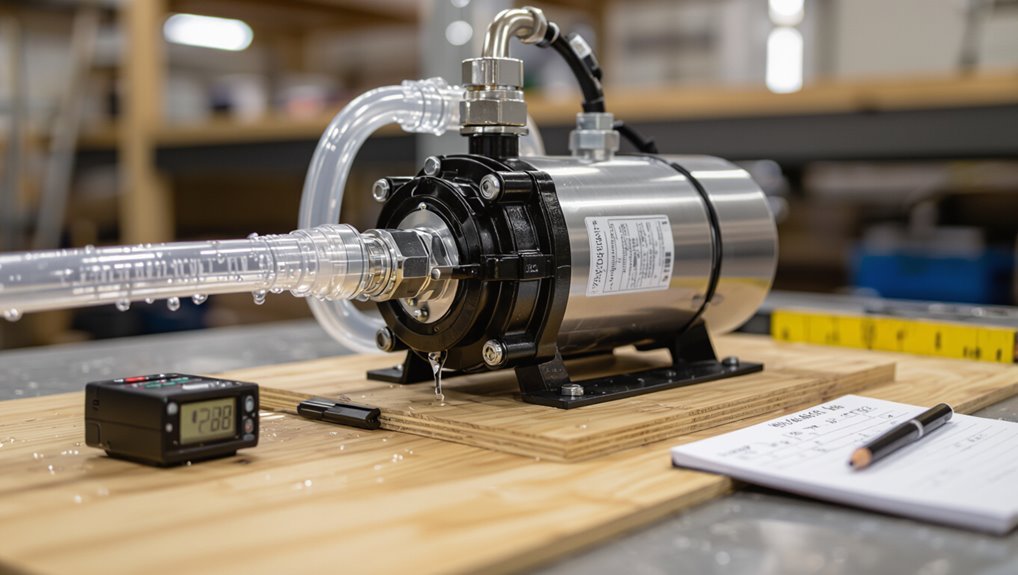
A correct condensate pump is selected by matching required flow rate and discharge head to the HVAC system’s condensate production and piping elevation.
Proper sizing prevents overflow, reduces downtime, and preserves equipment efficiency.
Engineers should prioritize accurate measurements and conservative safety margins when specifying a pump.
One-sentence summary of the correct sizing approach
One clear rule guides correct condensate pump sizing: match the pump’s flow capacity to the system’s condensate generation rate while ensuring the pump head overcomes the total static lift and friction losses, with margin for intermittent surges and future load increases.
For HVAC professionals, how to size a condensate pump reduces to selecting a unit whose performance curve meets peak condensate flow and required head plus safety margin.
Why proper condensate pump sizing matters for HVAC systems
Proper condensate pump sizing directly affects system reliability, energy use, and maintenance demands in HVAC installations.
Correct sizing prevents overflow, reduces compressor and coil corrosion risk, and guarantees timely condensate removal.
Oversized or undersized pumps cause cycling, wasted energy, premature failure, and increased service calls.
Accurate calculations optimize capacity, head, and safety controls, lowering lifecycle costs and improving uptime.
Condensate Pump Basics Every HVAC Pro Must Know
A condensate pump removes condensate from HVAC equipment and is commonly used with high-efficiency furnaces, air handlers, rooftop units, and commercial chillers where gravity drainage is impractical.
HVAC professionals should recognize basic pump types—submersible, external (in-line), and gravity-assisted units—and match selection to the installation.
Key specs to check are flow rate, total dynamic head (TDH), switch type (float or electronic), and tank capacity.
What a condensate pump does and common applications
Handles condensate removal from HVAC systems. The condensate pump collects water from coils, pans, or drains and moves it to an appropriate disposal point when gravity drainage is impractical.
It prevents overflow, protects equipment and structures, and enables flexible equipment placement. Common applications include rooftop units, split systems in basements or attics, commercial chillers, and condensing boilers where condensate must be lifted, routed, or neutralized.
Types of condensate pumps (submersible, external, gravity-assisted)
Condensate pumps come in three primary configurations—submersible, external (inline), and gravity-assisted—each suited to different installation constraints and maintenance preferences.
Submersible units sit within a reservoir for compact installs; external pumps mount inline for accessible servicing; gravity-assisted systems rely on elevation and simple drainage where feasible.
- Space-limited installs
- Service-access priority
- Low-complexity, passive drainage
Typical performance specs: flow rate, head (TDH), switch type, tank capacity
Several key performance specs determine a pump’s suitability for a given HVAC condensate application: flow rate, total dynamic head (TDH), switch type, and tank capacity.
Flow rate must exceed condensate generation peak. TDH includes static lift plus friction loss.
Switches can be mechanical float, optical, or electronic for reliability and reset behavior.
Tank capacity affects pump cycle frequency and overflow protection.
Required Data and Measurements Before You Begin
Before sizing a condensate pump, the technician compiles key measurements: measured or estimated condensate flow rates, expected condensate from equipment load and dew point, and the required vertical lift plus equivalent pipe length for head calculation.
They also record condensate temperature, water quality, and trap condition because these affect materials, seals, and pump type.
Accurate, documented inputs guarantee the selected pump meets capacity and longevity requirements.
Measuring condensate flow: methods and tools
Accurate measurement of condensate flow is essential to selecting a pump with the correct capacity and reliability; this requires choosing an appropriate method—such as volumetric collection, inline flow metering, or trap cycle counting—and the right tools for the system’s size and conditions.
Technicians should use graduated containers, calibrated flowmeters, ultrasonic or magnetic sensors, and dataloggers.
Record steady and peak rates, operating cycles, and temperature to size pump head and flow.
Calculating expected condensate from equipment load and dew point
A handful of key inputs—equipment heat load, inlet air temperature, and dew point—are required to estimate condensate generation reliably.
Using sensible enthalpy or psychrometric calculations, determine moisture removed per hour from differential humidity and airflow.
Convert pounds or kilograms of water per hour to gallons or liters.
Include latent load fraction, cycling factors, and safety margin to size pump capacity accurately.
Determining vertical lift and equivalent pipe length for head calculation
When sizing the condensate pump, determine the vertical lift from the condensate outlet to the highest discharge point and measure the actual run of piping—including rises, drops, and offsets—to calculate friction losses.
These two values (static head and equivalent pipe length) are the primary inputs for total dynamic head and must be measured on-site rather than estimated from drawings whenever possible.
Record fittings, pipe diameter, material, and flow rate to compute friction and safety margin accurately.
Identifying temperature, water quality, and trap conditions that affect pump selection
Several key measurements must be collected before selecting a condensate pump: condensate temperature, water quality (including pH, mineral content, suspended solids, and corrosion indicators), and the state of any installed steam traps (leakage rates, trap type, and sequencing).
Record temperature range and cycles, test for hardness, chlorides, and conductivity, inspect for oil or chemicals, and quantify trap blow-by or failures to size materials, seals, and capacity appropriately.
Step-by-Step Sizing Process
The sizing process begins with calculating condensate production (gal/hr or L/hr) and applying a safety margin to establish the required flow rate.
Next, total dynamic head is determined by summing vertical lift, pipe friction, and discharge pressure, and a pump whose capacity curve meets the flow-versus-head requirement is selected.
Finally, switch settings, reservoir size, and cycle frequency are verified to guarantee reliable operation.
Step 1 Calculate condensate production (gal/hr or L/hr)
Accurately determining condensate production in gallons or liters per hour is the essential first step in pump sizing, because it defines the required flow capacity and influences all subsequent selections.
The technician calculates condensate from equipment latent heat removal, runtime, and dewpoint conditions or uses manufacturer drain rates.
Sum all sources, convert units consistently, and document peak and average generation for sizing reference.
Step 2 Determine required flow rate with safety margin
With condensate production established, the next task is to set a target flow rate that includes a safety margin above the measured peak generation.
The installer selects a margin (commonly 20–30%) to cover surges, system aging, and measurement uncertainty.
Multiply peak condensate rate by (1 + margin).
Round up to the nearest standard pump capacity and document assumptions for maintenance and verification.
Step 3 Calculate total dynamic head (vertical lift + friction + discharge pressure)
Step 3 calculates total dynamic head by summing vertical lift, pipe friction losses, and any discharge backpressure, expressed as an equivalent head in feet or meters of water.
The technician adds static lift (pump inlet to discharge elevation), estimates friction loss using pipe length, diameter, fittings and flow rate, then converts discharge pressure to head.
The result sets required pump head.
Step 4 Select pump capacity curve to match flow vs head
Now the technician compares the calculated total dynamic head and required condensate flow against manufacturer pump curves to identify a model whose flow–head performance intersects the system point near the pump’s best efficiency range.
This guarantees the selected pump can deliver the required condensate rate at the computed head while minimizing energy use and avoiding operating points that cause cavitation or excessive wear.
The chosen curve confirms margin for blockage, aging, and safety.
Step 5 Verify switch settings, reservoir size, and cycle frequency
Confirm switch setpoints, reservoir volume, and pump cycle frequency against the calculated condensate load and head to secure reliable, efficient operation.
Verify float or pressure switch activation points prevent short cycling and allow sufficient drawdown.
Ascertain reservoir capacity accommodates peak runtime plus safety margin.
Calculate expected cycles per hour and adjust setpoints or reservoir size to minimize wear while maintaining required discharge intervals.
Step 6 Check electrical requirements and motor compatibility
At this stage, evaluate the pump’s electrical needs and motor compatibility against site power characteristics and control wiring to secure safe, reliable operation.
Confirm voltage, phase, and frequency match supply; verify full-load amperage and service breaker sizing; ascertain motor enclosure and NEMA ratings suit environment; check thermal protection, starter type, and control interlocks; confirm grounding and conduit capacity for installation.
Step 7 Validate with manufacturer curves and field testing
With electrical and motor parameters verified, the next step is to validate pump selection against manufacturer performance curves and perform field testing to guarantee real-world operation matches calculated requirements.
The technician compares duty point (flow vs head) to curves, confirms NPSH margin, checks motor load and protection, and conducts on-site performance tests (flow, pressure, leak-free installation).
Adjust selection or system as needed.
Practical Calculation Examples
The article presents three practical calculation examples to illustrate the sizing procedure:
Example A covers a single residential furnace/AC coil.
Example B addresses a multi-split commercial VRF system.
Example C treats a high-condensate rooftop unit with a long discharge run.
Each example includes worked calculations that determine required flow and head, plus the selected pump model that meets those criteria.
Readers can compare the scenarios to understand how system scale and discharge conditions affect pump selection.
Example A Sizing for a single residential furnace/AC coil
Example A examines sizing a condensate pump for a single residential furnace/air-conditioning coil by walking through a practical calculation using typical equipment ratings and installation conditions.
Using coil condensate rate (0.5–1.0 gph), vertical lift (10 ft), and horizontal run (15 ft), required head and flow determine pump selection.
Safety margin and overflow switch placement are verified; chosen pump meets gph and head with 20% buffer.
Example B Sizing for a multi-split commercial VRF system
Begin by outlining a realistic scenario for a multi-split VRF installation in a commercial space—multiple indoor units serving varied zones with differing capacities and drain paths.
Calculate combined condensate by summing individual unit drip rates.
Apply safety factor (typically 1.25) and select pump with flow-rate and head to handle peak aggregate flow plus vertical lift and friction losses.
Include redundant inlet capacity.
Example C High-condensate rooftop unit with long discharge run
A different scenario considers a single high-capacity rooftop unit producing a large condensate load that must be pumped across a long horizontal run to a distant roof drain.
The example highlights required flow rate, static head from elevation plus friction losses, inlet conditions, and trap/vent considerations.
It emphasizes selecting piping size and routing to minimize head loss before determining pump specifications.
Worked calculations and selected pump model for each example
Proceed to calculate each scenario step by step, converting condensate mass flow to volumetric flow, summing static lift and frictional losses to establish total dynamic head, and matching the resulting flow-head pair to pump performance curves. Results list computed flow, total dynamic head, and selected pump model for each example.
| Example | Flow (GPH) | Pump Model |
|---|---|---|
| A | 150 | CP-150 |
| B | 320 | CP-320 |
Installation and Commissioning Considerations
Proper siting of the pump and secure condensate pan connections are emphasized to guarantee reliable drainage and avoid backflow.
Attention is given to piping practices that minimize frictional head loss and prevent siphoning, along with correct electrical wiring, selection and placement of floats/switches, and alarm integration.
A concise commissioning checklist and initial performance verification procedures are outlined to confirm capacity, flow rates, and safe operation.
Proper siting of the pump and condensate pan connections
Locate the condensate pump and pan connections to minimize horizontal run and prevent low spots where water can pool, ensuring gravity-assisted flow into the pump inlet.
Position the pump close to served equipment, accessible for inspection and maintenance.
Mount pans with slight tilt toward the connection.
Maintain clearances for condensate overflow switches and wiring.
Avoid vibration transmission and exposure to freezing conditions.
Piping best practices to minimize head loss and prevent siphoning
With the pump and pan positioned to promote gravity feed and accessibility, attention turns to piping strategies that reduce pressure losses and eliminate siphon formation.
Use straight runs, minimize fittings and sharp bends, increase pipe diameter where velocity-induced losses occur, and slope condensate lines toward the pump.
Include accessible cleanouts, air breaks or vacuum vents to prevent siphoning, and secure piping to avoid sagging.
Electrical wiring, float/switch types, and alarm integration
Begin by planning the electrical layout, selecting float/switch types, and specifying alarm integration requirements to guarantee reliable operation and code compliance.
Detail circuit sizing, grounding, and local disconnects per code. Choose normally open/closed or dual-level floats and solid-state level sensors compatible with control logic.
Integrate audible/visual alarms and remote fault contacts, ensuring wiring runs, surge protection, and conduit meet site and manufacturer specifications.
Commissioning checklist and initial performance verification
Commissioning the condensate pump requires a methodical checklist to verify installation, electrical connections, controls, and safe operation before placing the system into service.
A concise verification routine confirms capacity, discharge head, and alarm function.
Follow this numeric checklist for initial performance checks:
- Verify pump flow, head, and run/duty cycle under expected load.
- Test float/switch actuation and alarm response.
- Confirm condensate piping slope, traps, and leak-free joints.
Common Sizing and Installation Mistakes to Avoid
Common mistakes include undersizing flow or underestimating required head, which leads to poor drainage and pump overload.
Failing to account for cycle frequency and short‑cycling, neglecting water quality and fouling risks or limiting maintenance access, and mismatching float or pressure switch cut‑in/cut‑out settings with system demands all shorten equipment life and reduce reliability.
Addressing these issues up front prevents performance failures and costly rework.
Undersizing flow or underestimating head
Many condensate-pumping failures stem from undersized flow capacity or underestimated head requirements, which prevent reliable condensate removal and can cause overflow, equipment cycling, or pump burnout.
HVAC professionals must calculate peak condensate rates, total dynamic head (including vertical lift, friction losses, and outlet fittings), and add appropriate safety margin.
Selecting a pump without matching these parameters invites clogs, repeated maintenance, and premature failure.
Ignoring cycle frequency and short-cycling risks
Neglect of cycle frequency and the risk of short-cycling undermines pump reliability and increases maintenance needs.
Frequent on/off cycling accelerates wear, overheats motors, and causes premature switch failure.
Designers should account for condensate generation patterns, reservoir sizing, and control hysteresis to minimize cycles.
Properly matched pump duty and correct float or level-control settings extend service life and reduce downtime.
Overlooking water quality, fouling, and maintenance access
Although often treated as secondary concerns, water quality, fouling potential, and ease of maintenance directly determine condensate pump performance and service life; corrosive or mineral-laden condensate accelerates component degradation.
Biological growth and scale reduce flow and trigger frequent cycling, and inaccessible installations make routine cleaning or repair costly and rare.
Regular water testing, strainers, removable access panels, and scheduled cleaning prevent capacity loss, clogs, and premature failures.
Mismatching switch cut-in/cut-out with system requirements
Water quality and access issues often expose weaknesses in control components, bringing attention to another frequent error: mismatching float or pressure switch cut-in and cut-out settings with the system’s operating needs.
Incorrect settings cause short cycling, overflow, or insufficient drainage. Techs must verify pump head, reservoir volume, and condensate rate, then select and set switches to match expected minimum and maximum operating points.
Maintenance, Troubleshooting, and Lifespan Factors
Routine inspection and cleaning schedules help maintain condensate pump reliability and prevent common failures.
Clear symptoms of undersized pumps—frequent cycling, overflow, or reduced condensate removal—should prompt systematic diagnostics such as flow measurements, head verification, and check-valve inspection.
Decisions to repair, replace, or upgrade depend on component condition, recurring faults, and changed system demands.
Routine inspection and cleaning schedule
Establish a regular inspection and cleaning schedule to preserve condensate pump reliability and prevent common failures; inspections should occur at least quarterly with more frequent checks in heavy-use or high-debris environments.
Include visual pump and reservoir checks, float and switch operation tests, inlet/outlet and tubing clearance, and drain-line flushing.
Record findings, replace worn components, and schedule immediate service if corrosion, persistent clogs, or electrical faults are detected.
Symptoms of insufficient pump sizing and diagnostic steps
After instituting a regular inspection and cleaning schedule, technicians should watch for signs that a condensate pump is undersized for the system it serves.
Common symptoms include frequent overflow, repeated float activation, slow drain during peak load, and motor cycling.
Diagnostic steps: measure condensate flow rate, verify head height, inspect check valve and discharge for restrictions, and compare measured values to pump specifications.
When to repair vs. replace; upgrade triggers
Determining whether to repair, replace, or upgrade a condensate pump depends on a concise assessment of performance, cost, and risk: evaluate the pump’s age and service history, the frequency and severity of failures, parts availability and repair cost relative to replacement, and whether existing capacity or features meet current and anticipated system demands.
Replace when failures recur, efficiency or capacity is inadequate, parts are obsolete, or upgrades yield significant reliability or code benefits.
Selection Checklist and Quick Reference Tables
A concise on-site data checklist outlines the minimum measurements and observations required for proper pump selection, including condensate flow rates, temperature, pressure, and drain locations.
Complementing this, quick reference tables present typical condensate rates for common equipment and the recommended pump capacity and head ranges to match those loads.
Together these tools streamline selection by ensuring decisions are based on measured conditions and industry-typical benchmarks.
Minimum data checklist to collect on-site
Several essential data points must be gathered on-site before selecting a condensate pump; these form the selection checklist and quick-reference tables used to match system requirements with available pump capacities.
Measure condensate flow rate, peak and average. Record static lift, horizontal run, and elevation changes.
Note temperature, condensate acidity, trap sizes, and number of connected units.
- Flow rate
- Lift/run
- Conditions/materials
Quick reference table for common equipment condensate rates and recommended pump ranges
With site measurements in hand, a compact quick-reference table maps common equipment types to typical condensate production rates and matching pump capacity ranges. The table below gives fast guidance; verify with measured rates and safety margins before final selection.
| Equipment | Condensate rate / Pump range |
|---|---|
| Residential furnace | 0.5–2 GPD / 1–3 GPD |
| PTAC unit | 2–4 GPD / 3–6 GPD |
| Small rooftop AHU | 10–20 GPD / 12–30 GPD |
| Large commercial AHU | 30–80 GPD / 40–100 GPD |
Advanced Topics and Special Scenarios
The discussion now turns to advanced considerations such as handling acidic condensate and corrosive environments, and configuring multi-zone systems with multiple condensate sources feeding a single pump.
It also covers selections for energy-efficient, low-noise pump options and strategies for integrating condensate recovery and reuse systems.
Practical guidance will address materials, piping arrangements, controls, and trade-offs for these special scenarios.
Handling acidic condensate and corrosive environments
A significant portion of condensate encountered in high-efficiency boilers, steam systems treating acidic feedwater, and certain industrial processes can be acidic and highly corrosive.
This requires materials and pump selections that resist chemical attack and avoid rapid degradation.
Specify corrosion-resistant materials (PVDF, Hastelloy, stainless alloys), chemical-resistant seals and tubing, trapped neutralization tanks or inline neutralizers, and verify compatibility, pH monitoring, and maintenance intervals.
Multi-zone systems and multiple condensate sources on one pump
When condensate from multiple zones or pieces of equipment must be collected into a single pump, careful planning of piping, controls, and capacity prevents backflow, cross-contamination, and overload.
Separate trap and check valve arrangements, properly sized inlet lines, and individual float switches or level sensors with interlocks guarantee reliable operation.
Calculate combined flow rates, include safety margin, and provide accessible maintenance points.
Energy-efficient and low-noise pump options
Many modern condensate pumps prioritize energy efficiency and quiet operation by combining high-efficiency motors, variable-speed drives, and vibration-isolating mounts to reduce power consumption and audible noise without sacrificing capacity.
Selection favors ECM or brushless motors, sound-attenuated housings, and PWM control for duty cycling.
Consider low-start torque for thin films, manufacturer noise ratings (dB), and standby power to optimize lifecycle costs.
Integrating condensate recovery and reuse systems
Integrating condensate recovery and reuse systems involves capturing condensate from HVAC, steam, or process equipment, treating it to meet quality requirements, and redirecting it for applications such as boiler feedwater, makeup water, or irrigation to reduce water and energy consumption.
System design addresses storage, filtration, neutralization, and controls; pump sizing accounts for return head, intermittent flow, and code requirements to guarantee reliability and safety.
Final Verification and Handover to Client
The final verification package should include all calculations, pump curves, and equipment manuals assembled for client reference and future troubleshooting.
A concise, customer-facing explanation of pump operation and the recommended maintenance frequency should accompany the technical files.
Responsibility for sign-off and transfer of documents should be clarified before project closeout.
Documentation to include with handover (calculations, curves, manuals)
Provide a detailed documentation package that consolidates all calculations, pump and system curves, manufacturer manuals, wiring diagrams, test reports, and commissioning records required for the client’s operation, maintenance, and future verification of the condensate pump system.
Included documents should be clear, indexed, and versioned.
Recommended contents:
- Sizing calculations and head/flow curves
- Electrical schematics and control settings
- Manufacturer manuals, parts lists, and test reports
Customer-facing explanation of pump operation and maintenance frequency
Several straightforward explanations and a clear maintenance schedule will equip the client to operate the condensate pump safely and reliably.
The handover sheet summarizes normal operation, alarm indicators, and emergency shutoff steps. It lists routine tasks: monthly visual check, quarterly float and switch test, biannual cleaning, and annual service by a technician.
Contact details and warranty conditions are included for prompt support.
Conclusion
To sum up, the HVAC professional finishes the condensate pump sizing with confidence, having followed methodical measurements and checks. Like a watchmaker winding a brass pocket watch, they acknowledge both precision and patience matter. The chosen pump meets flow, head, and safety needs while allowing room for future changes. Clear documentation and client handover complete the job, ensuring reliable operation and peace of mind for building occupants and operators alike.