How to Repair a Well Pump: Step-by-Step Troubleshooting and Fixes for Homeowners
To effectively repair a well pump, homeowners can follow a clear troubleshooting process. Start by confirming power and wiring, then inspect the pressure switch and tank air charge. Listen for unusual motor noises and check for leaks, clogged intakes, or faulty check valves. Essential tools include a multimeter, pressure gauge, and basic hand tools; always shut off power and wear PPE for safety. While simple parts like capacitors, switches, and valves can be replaced, complex electrical issues or deep-well repairs should be handled by a professional. Follow the step-by-step guide for detailed troubleshooting and repair tips.
What a Well Pump Does and When It Needs Repair
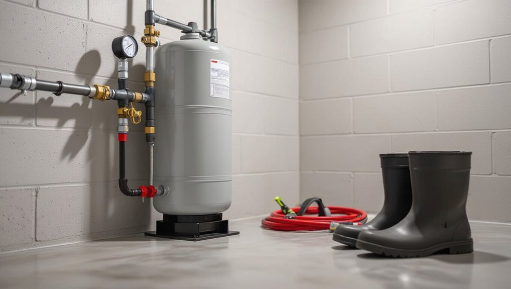
A well pump moves groundwater into a pressure tank and plumbing system using components such as the motor, impeller or piston, check valve, and pressure switch.
Failure often shows as low or fluctuating pressure, frequent cycling, strange noises, or loss of power.
Before any inspection, power should be shut off and basic safety precautions observed to avoid electrical shock, contamination, or injury.
How well pumps work (basic components and operation)
Well pumps move groundwater from a well to a household plumbing system by converting mechanical or electrical energy into water pressure.
Understanding their basic components—pumphead, motor, impeller or piston, check valve, pressure switch, and pressure tank—clarifies both normal operation and common failure points.
The homeowner or technician assesses component function, electrical supply, and plumbing connections when learning how to repair a well pump efficiently and safely.
Common signs your well pump is failing
After learning how the pumphead, motor, impeller or piston, check valve, pressure switch, and pressure tank work together, attention shifts to recognizing when those components begin to fail.
Common signs include low or fluctuating water pressure, frequent cycling, unusual noises, air in taps, muddy or metallic water, slow recovery after use, and motor overheating or tripping breakers—each indicating specific component wear or malfunction.
Safety considerations before inspecting a well pump
Because inspecting a well pump involves electrical, mechanical, and contamination risks, the inspector must prioritize personal and system safety before any hands-on work.
Confirm power is off, lock out and tag circuits, and verify with a tester.
Wear PPE—gloves, eye protection, and boots.
Prevent chemical or biological exposure, guarantee stable footing, secure tools, and have emergency contact information available.
Quick Assessment Checklist to Diagnose a Faulty Well Pump
A quick assessment begins by verifying power and electrical supply to the pump to rule out simple faults.
Next, water pressure and flow rate are checked while listening and observing for unusual noises or rapid cycling that indicate internal problems.
Finally, visible components—pressure tank, pressure switch, pipes, and fittings—are inspected for leaks, corrosion, or loose connections.
Verifying power and electrical supply
Begin by confirming that the well pump has reliable electrical service before inspecting mechanical components.
Check the main breaker, subpanel, and any dedicated pump disconnect for tripped or damaged switches.
Verify voltage at the control box with a multimeter and inspect wiring for corrosion, loose connections, or burnt insulation.
Test the safety switch, pressure switch, and any fuses for continuity before proceeding.
Checking water pressure and flow rate
Start by measuring both static and dynamic pressure and evaluating flow rate to determine whether the pump or system is underperforming.
Record static pressure with no demand, then run a timed flow test to calculate gallons per minute.
Compare results to pump specifications and household needs.
Note pressure drop under load, inconsistent flow, or slow recovery; these indicate worn pump, clogged lines, or pressure tank issues.
Listening and observing for unusual noise or cycling
Listen for irregular sounds and watch for rapid or frequent on/off cycles, as these are immediate indicators of mechanical or pressure-related faults in a well pump system.
Note grinding, squealing, knocking, or rattling and whether noise changes with flow demand.
Observe cycle timing and pump run duration.
Document patterns, times, and conditions to guide diagnosis or technician consultation.
Inspecting visible components: pressure tank, pressure switch, pipes, fittings
Inspect the visible components—pressure tank, pressure switch, pipes, and fittings—for obvious signs of wear, leaks, corrosion, or loose connections, since these external clues often pinpoint common causes of pump failure.
Note bulging or waterlogged tanks, pitted switch contacts, frayed wiring, dripping joints, and rusted clamps.
Tighten fittings, replace damaged parts, and document findings before further electrical or well-head diagnostics.
Tools and Materials Needed for Well Pump Troubleshooting and Repair
The following section outlines the basic tools, spare parts, and decision points for well pump troubleshooting and repair.
- Multimeter, pipe wrenches, wire strippers and other electrical/plumbing diagnostics tools
- Common replacement parts: capacitors, pressure switches, check valves, and seals
- Criteria for calling a professional versus attempting a DIY repair based on safety, complexity, and available parts
Essential tools for electrical and plumbing diagnostics
Several basic electrical and plumbing diagnostic tools are indispensable when troubleshooting a well pump.
A multimeter for voltage, continuity, and resistance checks; a clamp ammeter for current draw; non-contact voltage tester for safety; pressure gauge and vacuum gauge for system diagnostics; pipe wrench set, adjustable wrench, pliers, and tubing cutters for plumbing access; insulation and electrical tape, and GFCI/tester for safety verification.
Replacement parts commonly stocked for repairs
Common replacement parts stocked for well pump repairs include wear items and electrical components that fail most often.
Typical inventory: pressure switches, control relays, capacitors, start/run kits, check valves, foot valves, pump seals, impellers, shaft bearings, O-rings, pressure tanks bladder patches, wiring connectors, fuses, and inline strainers.
Stock selection matches pump type, model, and local water conditions to minimize downtime.
When to call a professional vs. DIY
After listing stocked parts for routine fixes, determining whether a homeowner should attempt a repair or summon a professional depends on the problem’s complexity, required tools, and safety risks.
Minor tasks—pressure switch adjustment, capacitor replacement, basic plumbing—are suitable for DIY with proper instructions.
Call a licensed pump technician for electrical hazards, deep-well pulls, motor failures, contamination concerns, or when diagnostics exceed the homeowner’s tools or experience.
Step-by-Step Troubleshooting for Shallow and Submersible Pumps
The following steps guide systematic troubleshooting for both shallow and submersible well pumps, beginning with a safety shutdown and isolation of the system.
Technicians should then verify electrical components—circuit breaker, fuses, control box, and by measuring voltage and amperage at the pump—followed by inspection and testing of the pressure switch and tank.
Finally, checks of check valves, foot valves, and suction lines confirm proper flow and prevent backflow issues.
Preliminary safety shutdown and isolation
Before any diagnostic or repair work begins, power to the well pump system must be fully isolated and locked out to prevent accidental energization; this includes switching off the appropriate breaker at the main panel and confirming power absence with a non-contact voltage tester at the control box and motor leads.
Next, close and tag any upstream valves, drain pressure from the system, and ground exposed conductors.
Testing the circuit breaker, fuses, and control box
Begin by visually and electrically inspecting the breaker, fuses, and control box to identify obvious faults such as tripped breakers, blown fuses, burned contacts, loose wiring, or corrosion.
Verify voltage with a multimeter at supply and motor terminals, test fuse continuity, and check breaker operation under load.
Tighten connections, clean corrosion, and replace damaged fuses or breakers before restoring power.
Inspecting and testing the pressure switch and tank
Move on to the pressure switch and tank next, since faults here commonly mimic pump or electrical failures.
Inspect for corrosion, burned contacts, loose wiring, and proper mounting. Check switch tolerance and settings, then depress the lever to observe operation.
Examine pressure tank air charge with a tire gauge, compare to cut-in minus 2 psi, and adjust or service bladder-style tanks as needed.
Measuring voltage and amperage at the pump
With the pressure switch and tank verified, attention shifts to measuring voltage and amperage at the pump to determine whether the problem is electrical or mechanical.
A multimeter checks supply voltage at motor leads; compare readings to nameplate.
A clamp ammeter measures running and startup current; excessive draw indicates mechanical binding or impeller issues, while low or absent current suggests wiring, control, or motor failure.
Checking check valves, foot valves, and suction lines
Inspecting check valves, foot valves, and suction lines is essential to distinguish between pressure loss caused by valve failure, air leaks, or blocked intake in both shallow and submersible systems.
Technicians should verify valve seating, listen for steady flow or rattling, check for seepage at joints, and confirm suction-line integrity.
Replace worn valves, tighten or reseal fittings, and clear visible obstructions before further diagnostics.
Diagnosing air-locks, cavitation, and sediment issues
Air entrainment, cavitation, and sediment accumulation each produce distinct symptoms and require different corrective actions. The technician systematically isolates and identifies the root cause before component replacement.
The technician inspects suction lines, joins, and air vents for leaks; listens for knocking or gasping indicating cavitation; checks flow patterns and pressure drops; and examines filters, screens, and well water for particulate buildup. Then, remedies accordingly.
How to Repair Specific Common Problems
The guide next addresses fixes for the most common well pump failures, from electrical problems to mechanical wear.
It covers diagnosing and repairing no-power conditions, priming and suction leaks, pressure tank and switch adjustments for short cycling, and remedies for low pressure including impeller replacement and tank sizing.
Guidance on diagnosing loud or unusual noises and repairing bearings, motors, or clearing debris is provided.
No power to pump electrical fixes and wiring checks
Several simple electrical issues commonly cause a well pump to lose power, and methodical checks can quickly identify the problem.
The homeowner should inspect breakers, fuses, control box, and visible wiring for tripped, burned, or corroded connections.
Test voltage at the pump and pressure switch with a multimeter.
Replace damaged components, tighten terminals, and verify grounding.
Call a licensed electrician for high-voltage work.
Pump runs but no water priming, suction leaks, and valve repairs
Begin troubleshooting by confirming the pump is running but failing to deliver water, since this condition typically indicates priming loss, suction leaks, or faulty valves rather than electrical faults.
Check suction line for air leaks, tighten fittings, and inspect foot valve or check valve for debris or wear.
Reprime per manufacturer, replace damaged valves or gaskets, and retest flow and pressure for sealing integrity.
Short cycling pressure tank issues and pressure switch adjustment
After confirming that priming, suction leaks, and valve problems are not responsible for poor output, attention shifts to the pressure tank and switch when the pump cycles on and off rapidly.
The tank’s air charge can be low or bladder-failed; check with a tire gauge and correct to cut-in minus 2 psi.
Inspect and clean switch contacts, verify correct cut-in/cut-out settings, and replace faulty switches.
Low water pressure cleaning, impeller replacement, and pressure tank capacity
Diagnose low water pressure by isolating likely causes—clogged intake screens, worn impellers, or an undersized or waterlogged pressure tank—and prioritize inspection steps based on accessibility and symptoms.
Clean or replace clogged screens, flush sediment from the pump housing, and evaluate impeller wear; replace impellers when erosion or damage reduces flow.
Measure tank precharge and capacity; repair or replace a waterlogged or undersized pressure tank.
Pump makes loud or unusual noises bearings, motor failure, or debris
Once mechanical sources are ruled out and intake/screens, impellers, and the pressure tank have been addressed, attention shifts to noises that indicate bearing wear, motor problems, or foreign debris.
The technician inspects shaft coupling, bearings, and seals for grinding or play, checks motor mounting and alignment, and listens for rattles suggesting debris.
Replace worn bearings or damaged motor components; remove lodged material and retest operation.
Intermittent operation control box, capacitors, and thermal overloads
When intermittent pump cycling persists despite correct plumbing and a healthy pressure tank, attention turns to the electrical control components: the control box, start/run capacitors, and thermal overloads.
Inspect the control box for burnt contacts or loose wiring.
Test capacitors with a multimeter or replace if bulging.
Check thermal overloads for proper reset function; replace failed relays or overloads to restore consistent operation.
Leaks at joints and fittings sealing, pipe replacement, and corrosion remedies
Address leaks at joints and fittings by first isolating the affected section and relieving pressure to prevent further escape of water.
Inspect threads, unions, and soldered joints; tighten, rethread with pipe tape, or replace damaged fittings.
Replace corroded pipe segments with compatible materials (PVC, stainless, or coated steel).
Apply appropriate corrosion inhibitors and sacrificial anodes where applicable.
Test under pressure and monitor for recurrence.
Frozen or winterized systems thawing and prevention of freeze damage
Thawing a frozen or winterized well system requires a controlled, stepwise approach to prevent pipe rupture, pump damage, and contamination.
Begin by isolating electrical power and opening faucets to relieve pressure.
Apply gentle, even heat to exposed lines with heat tape or warm air; avoid open flames.
Inspect for leaks, sanitize if contamination is suspected, and insulate or winterize to prevent recurrence.
Replacing a Well Pump: When and How
When a well pump shows persistent failures or repair costs approach replacement price, the decision to replace should weigh long-term reliability and matching system requirements.
The discussion covers selecting the correct pump type and capacity, safe removal and installation procedures for both submersible and jet/shallow-well pumps, and the necessary steps for reconnection, priming, and testing.
Clear attention to compatibility and safe handling guarantees a successful replacement and restores proper system performance.
Deciding if replacement is necessary (cost vs. repair)
How should a homeowner weigh repair versus replacement of a failing well pump? The decision rests on pump age, repair frequency, cost of parts and labor, and remaining expected life.
Compare repair estimates to replacement price, factoring in energy efficiency, warranty, and future reliability. If repairs approach half or more of replacement cost or failures recur, replacement is usually more economical.
Choosing the right pump type and capacity
After deciding replacement is preferable to repeated repairs, the homeowner must select a pump type and size that matches the well’s characteristics and household demand. Consider well depth, flow rate, pressure needs, and drawdown. Match pump curve to system and factor efficiency, reliability, and budget.
| Pump Type | Depth Suitability | Typical Use |
|---|---|---|
| Shallow jet | <25 ft | Surface wells |
| Submersible | Deep | Domestic supply |
| Convertible | Variable | Versatile applications |
Steps to remove and replace a submersible pump safely
Begin by shutting off power and isolating the well system to guarantee safety before any descent into mechanical work.
Inspect surface components, label wiring, and relieve line pressure.
Lower a clean rope and retrieval gear, disconnect electrical and drop pipe, then carefully lift the pump assembly.
Replace seals, check motor and cable integrity, reinstall with correct depth and torque, reconnect wiring, restore power, and test operation.
Steps to replace a jet or shallow-well pump
Replace a jet or shallow-well pump when performance drops, pressure cycles erratically, leaks develop, or repairs become uneconomical; turn off power, shut off supply, and drain system.
Disconnect piping, pressure switch, and electrical leads. Remove mounting and old pump.
Match new pump specifications, install secure fittings and check valve, reconnect wiring per code, anchor unit, then restore supply and power for system startup.
Proper reconnection, priming, and testing after replacement
With the new pump mounted and all piping and electrical connections loosely in place, attention turns to proper reconnection, priming, and testing to guarantee reliable operation.
Tighten fittings, secure wiring to code, and restore check valve and pressure switch settings.
Prime per manufacturer instructions, purge air, then power the unit briefly to verify flow.
Monitor pressure, listen for abnormal noise, and inspect for leaks.
Testing, Calibration, and Final Checks
After a pump replacement or repair, the technician performs a controlled test run to verify flow rate and system pressure against specifications.
Pressure switch cut-in and cut-out settings are adjusted as needed. Electrical grounding and safety connections are inspected and confirmed.
All repairs, replaced parts, and calibration settings are documented for future maintenance and warranty records.
How to test run and verify flow rate and pressure
Begin by energizing the system and observing gauges and flow indicators to confirm the pump operates within manufacturer specifications. This involves running the pump long enough for pressures and flow to stabilize while monitoring for irregular noises, leaks, or vibration.
Record steady-state pressure and flow using a calibrated gauge and flowmeter. Compare to expected values, document deviations, and repeat tests after any corrective action.
Adjusting pressure switch cut-in and cut-out settings
Adjust the pressure switch settings to guarantee the pump cycles between the correct cut-in and cut-out pressures, preventing short cycling or excessive run time.
Verify current settings with a reliable gauge, then power off and remove the cover.
Carefully turn the adjustment nut(s) to raise or lower cut-in/cut-out differential in small increments.
Restore cover, power, and test cycles under load.
Ensuring proper grounding and electrical safety
With the pressure switch set and verified, attention turns to grounding and electrical safety to protect the pump, the system, and anyone who services it.
Verify equipment grounding conductor continuity, tight connections at the motor, control box, and panel, and proper bonding to metal piping.
Confirm GFCI or local breaker protection functions, replace corroded clamps, and document test results for future reference.
Documenting repairs and parts for future maintenance
Record all repair actions, replaced parts, and test results immediately after completion to create a clear maintenance history that speeds future diagnostics and guarantees correct replacements.
Include dates, part numbers, supplier contacts, torque/settings, and voltage readings. Note anomalies, corrective steps, and calibration adjustments.
Store records digitally and as a hard copy with the pump manual. Review and update logs after each service for reliable long-term upkeep.
Preventive Maintenance to Extend Well Pump Life
A regular preventive maintenance plan promotes longer pump life by outlining inspection tasks, seasonal winterizing steps, and routine sediment or water-quality checks.
Specific items include pressure switch and seal inspections, flushing or filtration to control sediment, and winter preparations to prevent freezing damage.
Professional servicing should be scheduled for complex repairs or warranty compliance and documented to preserve coverage.
Routine inspection schedule and tasks
Because consistent checks catch small issues before they become failures, a defined routine inspection schedule is essential for extending a well pump’s service life.
Monthly visual checks, pressure readings, and noise monitoring detect anomalies early.
Quarterly tasks focus on electrical connections and pressure tank condition.
Annual checks verify flow rate and professional inspection.
- Visual inspection and leak check
- Pressure and amp draw measurement
- Electrical connections and tank integrity
Seasonal maintenance and winterizing tips
Seasonal maintenance guarantees reliable operation and prevents freeze-related damage by adapting care to changing temperatures and usage patterns.
Inspect insulation, heat tape, and well cap seals before cold weather. Drain and winterize exposed pipes and pressure tanks.
Verify pump cycles and pressure settings after seasonal temperature shifts.
Restore ventilation and remove temporary protections in spring to prevent moisture buildup and overheating.
Water quality considerations and sediment management
How does water chemistry and particulate load affect pump longevity?
Corrosive water (low pH, high dissolved solids) degrades metal components; abrasive sand and silt accelerate impeller and seal wear.
Regular testing, sediment traps, whole-house filtration, and periodic well flushing reduce damage.
Monitoring iron, manganese, hardness, and turbidity guides appropriate treatment to extend pump life and maintain reliable operation.
When to schedule professional service and warranty considerations
After addressing water chemistry and sediment control, owners should establish a clear schedule for professional inspections and know their warranty terms to protect pump longevity and avoid costly failures.
Schedule annual or biennial inspections, sooner if pressure, noise, or flow issues arise. Maintain service records, follow manufacturer maintenance requirements, and confirm whether DIY repairs void warranties; consult certified technicians for covered diagnostics and authorized repairs.
Common Mistakes to Avoid and Safety Reminders
The next section highlights frequent errors and safety precautions technicians should keep in mind when repairing a well pump.
It covers electrical hazards and the importance of lockout/tagout, the consequences of incorrect pump sizing or poorly executed installation, and problems caused by over-tightening, improper seals, or using incorrect parts.
Observing proper procedures and using correct components reduces risk of injury and equipment failure.
Electrical hazards and lockout/tagout practices
Many repair-related injuries stem from overlooked electrical hazards, so strict lockout/tagout procedures must be enforced before any well pump work begins.
Workers should isolate power, verify de-energization with a meter, attach visible locks and tags, and follow site-specific procedures.
Only qualified personnel may restore power.
Neglecting these steps risks lethal shock, equipment damage, and regulatory violations; documentation and training are essential.
Incorrect pump sizing and installation errors
Incorrect pump selection and improper installation are frequent causes of premature failure, reduced efficiency, and safety risks; installers must therefore match pump capacity, horsepower, and pressure characteristics to the well’s yield and system demand.
They must also guarantee correct motor-phase and voltage connections, and follow manufacturer torque, alignment, and suction/discharge piping guidelines.
Mis-sizing, inadequate support, incorrect check valve placement, and poor electrical grounding lead to cavitation, cycling, leaks, and equipment damage.
Over-tightening, improper seals, and using wrong parts
Avoid over-tightening fittings and forcing components together, as doing so damages threads, crushes seals, and creates leaks that worsen under pressure.
Use manufacturer-specified gaskets, O-rings, and thread sealant; mismatched materials cause corrosion, failures, and contamination.
Replace worn seals and source correct OEM or equivalent parts.
Verify torque specs, test under controlled conditions, and prioritize proper seals and correct components for reliable, safe operation.
Troubleshooting Scenarios and Real-World Examples
The section presents concise, real-world troubleshooting scenarios to guide practical diagnosis and repair.
It covers a stepwise approach for sudden loss of water after a storm, methods to isolate causes of low pressure at specific fixtures, and common reasons and fixes for rapid pump cycling following a repair.
Each scenario emphasizes systematic checks, likely fault causes, and prioritized corrective actions.
Scenario: Sudden loss of water after a storm stepwise diagnosis
When a storm is followed by a sudden loss of water, a logical, stepwise diagnosis begins with safety checks and moves outward from the pressure tank and wellhead to the pump and electrical system. This focused approach helps isolate whether the cause is a power outage, a tripped breaker or GFCI, surface flooding and contamination, a collapsed delivery line, a failed pressure switch, or a motor/pump malfunction requiring further testing.
Inspect power, breakers, GFCI, visible pipe damage, tank pressure, wellhead flooding, pressure switch condition, and wiring. Record findings, then perform targeted tests (voltage, continuity, pump run) or call a qualified technician if electrical or submerged motor issues are suspected.
Scenario: Low pressure at certain fixtures isolating the issue
Diagnose low pressure at specific fixtures by treating the problem as localized rather than systemic: inspect aerators, faucet cartridges, mixing valves, and individual shutoff valves for debris, calcification, or partial closure before assuming a pump or pressure-tank fault.
Test multiple outlets on the same supply line, check shower diverters and supply flex lines, clear or replace clogged components, then retest to confirm restoration.
Scenario: Pump cycles rapidly after repair root causes and fixes
Observe rapid cycling of a well pump as an urgent symptom indicating underlying issues such as a waterlogged pressure tank, faulty pressure switch, leaky check or foot valve, or intermittent wiring faults. Each cause produces similar on/off patterns but requires different fixes, so methodical isolation—starting with tank and switch checks, then inspecting valves and electrical connections—prevents unnecessary parts replacement.
Diagnose by checking tank air charge, switch adjustment, valve integrity, and wire continuity. Repair or replace the failed component and retest operation to confirm restored cycle frequency and system pressure stability.
Useful Resources, Parts Suppliers, and When to Hire a Pro
Consult reliable manuals, parts suppliers, and professional directories to streamline repairs and avoid costly mistakes; reputable sources include manufacturer service guides, local well-drilling companies, specialty pump retailers, and online forums maintained by licensed technicians.
Recommended steps include:
- Verify OEM part numbers and warranties before purchase.
- Use local licensed pump contractors for electrical or submersible work.
- Seek diagnostic service when diagnosis is unclear or risks safety.
Conclusion
Like a weathered traveler repairing a cart at the roadside, the homeowner who learns well pump care keeps life’s essentials flowing through storms and seasons. Small checks, timely fixes, and respect for safety turn mysterious failures into manageable tasks. When simple remedies fail, calling a skilled hand prevents greater ruin. In tending the pump, one preserves more than water—stability, peace of mind, and the quiet assurance of household resilience.