How to Remove the Top of an AC Unit Safely: Step-by-Step Guide and Tools Needed
To safely remove the top of an AC unit, follow these essential steps: First, isolate the power and discharge any capacitors. Always wear gloves, eye protection, and use insulated tools for safety. Gather necessary tools such as a cordless drill, wrenches, screwdrivers, socket set, gasket material, and any replacement parts. Before starting, inspect seals and ensure secure footing while implementing lockout/tagout procedures.
Clear any obstructions and disconnect electrical components. Support the fan and motor as you carefully unfasten the top, taking care to manage sharp edges. When reinstalling, use the proper grommets and torque the fasteners securely. Finally, test the motor operation to ensure everything is functioning correctly. Follow these guidelines for a safe and effective process.
How to Remove the Top of an AC Unit Safely Quick Overview
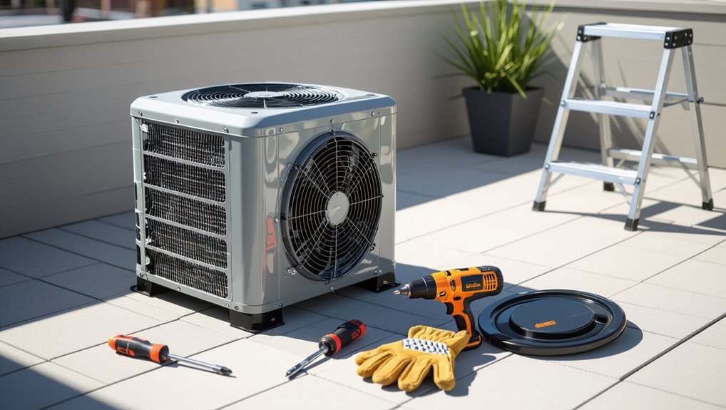
The article outlines common reasons to remove an AC unit top, such as cleaning coils, replacing parts, or diagnosing airflow problems.
It emphasizes a safety-first approach: power off the unit, wear protective gear, and follow manufacturer instructions.
Typical removal takes 20–60 minutes depending on unit complexity and technician experience.
When and why you might need to remove the top of an AC unit
Servicing an air conditioner sometimes requires removing its top cover to access the fan, motor, coils, or electrical components.
Technicians or informed homeowners may remove the top to clean coils, replace the fan motor, clear debris, inspect wiring, or diagnose airflow and vibration issues.
Learning how to remove the top of the AC unit enables targeted repairs, improves efficiency, and prevents minor problems from escalating.
Quick safety-first answer: essential precautions and expected time
Although it can be done by a careful homeowner, removing the top of an AC unit requires strict safety steps: disconnect power at the breaker, wait for capacitors to discharge, wear gloves and eye protection, and use insulated tools if working near wiring.
Additional precautions include clearing the area, securing panels, and avoiding wet conditions.
Expect 20–60 minutes for basic removal; longer if corrosion or stuck fasteners are present.
Tools, Materials, and Personal Protective Equipment Needed
A concise list of hand and power tools is provided to guarantee safe removal of the AC unit top, including screwdrivers, nut drivers, and a cordless drill.
Necessary materials and common replacement parts—gaskets, fasteners, and sealant—are recommended to have on hand.
Personal protective equipment and appropriate clothing, such as safety glasses, gloves, and closed-toe shoes, are specified to minimize injury risk.
Tools list
Several essential tools, materials, and personal protective items are required before attempting to remove the top of an AC unit to guarantee the task is efficient and safe.
Essential tools include:
- Cordless drill with screwdriver bits
- Adjustable wrench and socket set
- Flathead and Phillips screwdrivers
- Tape measure and flashlight
Protective gear: work gloves, safety glasses, and sturdy footwear.
Materials and replacement parts to have on hand
With tools and protective gear ready, attention shifts to the materials and replacement parts that should be on hand to complete the job without delays.
Essential items include common spares and consumables to address wear or damage discovered when the top is removed:
- Replacement fan blade and motor capacitor
- Coil cleaner and fin comb
- Sheet metal screws and gasket material
- Condensate pan sealant and tubing connectors
Personal protective equipment and clothing recommendations
Proper personal protective equipment (PPE) and appropriate clothing minimize injury and contamination risks when removing an AC unit top.
The technician should don gear that shields from sharp edges, debris, and chemical residues while maintaining mobility.
- Heavy-duty gloves gripping metal
- Safety glasses or face shield
- Long-sleeve work shirt and durable pants
- Steel-toe boots with good traction
Pre-Work Safety Checks Before Touching the Unit
Before any contact with the unit, the technician confirms the power is shut off and a lockout/tagout is applied to prevent accidental energization.
They verify there is no stored energy by discharging capacitors and ensuring fan blades are stationary.
They also assess weather and site conditions, confirming adequate clearance and stable footing for safe work.
How to power off and lock out the AC safely
Shut down the system and verify power isolation before any panel or fan work begins.
The technician locates the outdoor disconnect, turns off breakers and switches, tags and locks out the service per site procedures, and confirms isolation at the unit with a voltage tester.
Remaining crew are informed, written lockout records completed, and PPE is worn.
Operations remain suspended until work concludes.
Verifying absence of stored energy (capacitors, fans)
Confirm that all potential sources of stored energy are discharged before touching the unit.
Technician verifies capacitor discharge using a rated insulated tool and meter, observing manufacturer’s procedures.
Lockout/tagout confirmation guarantees power isolation.
Spin fan blades manually after shutdown to confirm no residual motion; verify fan motor capacitors are shorted per spec.
Document verification and proceed only when readings show zero potential.
Checking weather and site conditions (clearance, stability)
With stored-energy checks complete and documented, the technician assesses external conditions that could affect a safe lift of the unit top.
Wind, precipitation, and temperature are evaluated for worker safety and component handling. Surrounding clearance, nearby obstructions, and secure footing or platform stability are confirmed.
Access routes and overhead hazards are identified, and work is postponed or rescheduled if conditions compromise safe removal.
Assessing the Unit and Planning the Removal
The technician first identifies the unit type and top configuration—bolt-on, clip-held, or riveted—to determine required tools and removal difficulty.
They then locate all fasteners, wiring passes, and the positions of refrigerant lines and coils to avoid accidental damage.
Finally, they plan how to support components and sequence the work to maintain safety and accessibility throughout the removal.
Identifying the unit type and top configuration (bolt-on, clip, riveted)
Begin by visually inspecting the exterior of the air-conditioning cabinet and the fan housing to determine how the top is secured: look for visible bolts or screws along the perimeter, metal clips or folded tabs, and rows of rivet heads that indicate a permanently attached panel.
Note material (steel/aluminum), factory versus field modifications, and access clearance to plan appropriate tools and removal method.
Locating fasteners, wiring passes, and refrigerant/coil proximity
Several key attachment points and penetrations must be identified before any cutting or unfastening occurs:
Inspect all visible screws, bolts, clips, and spot welds around the top panel.
Trace wiring entry points and label conductors; note conduit, strain reliefs, and control boxes.
Map refrigerant lines and coil locations to avoid nicking tubing or fins.
Photograph layout for reference.
Planning for component support and work sequence
With fasteners, wiring entries, and refrigerant routing identified, an assessor should evaluate which components require temporary support and establish a clear work sequence to minimize risk and downtime.
They schedule tasks to disconnect power, brace fan motors, secure coil assemblies, and label connections. Required supports, tools, and personnel are listed.
A stepwise removal order preserves alignment, prevents strain on wiring, and expedites reassembly.
Step-by-Step Procedure to Remove the Top of an Outdoor Condenser Unit
The procedure begins with confirming power isolation and a final safety check before any physical work.
Next, external obstructions are removed and the work area secured, followed by careful disconnection of electrical connections and the release of fasteners.
Finally, the fan and motor assembly are lifted and supported for safe removal of the condenser top.
Step 1 Power isolation and final verification
Begin by ensuring all power sources to the outdoor condenser are isolated: shut off the dedicated circuit breaker and switch the external disconnect to the off position.
Verify isolation with a non-contact voltage tester at the unit’s terminal block and confirm zero voltage on multimeter probes.
Lockout/tagout per site protocol, wear insulated gloves, and only proceed when all readings definitively indicate no live power.
Step 2 Removing external obstructions and securing the area
After confirming power isolation and lockout/tagout, attention shifts to clearing the workspace around the condenser.
All loose debris, tools, plants, and movable objects are removed to provide unobstructed access.
Perimeter safety barriers or cones are placed.
Adequate lighting and stable footing are guaranteed.
Nearby pedestrians and pets are kept away until the procedure is complete.
Step 3 Disconnecting electrical connections safely
Disconnect all electrical feeds to the condenser before any panel removal or internal access, ensuring that incoming power, disconnects, and capacitor circuits are fully de-energized and verified with a properly rated meter. The technician tags breakers, wears insulated gloves, and grounds capacitors before disconnecting leads. Verify zero volts and secure loose wires to prevent contact or damage.
| Visual | Action |
|---|---|
| Gloves on | Tag breaker |
| Meter reading | Ground capacitor |
Step 4 Releasing and removing fasteners (bolts, screws, clips)
With power verified as zero and capacitors grounded, attention shifts to the fasteners securing the condenser top.
The technician inspects bolt, screw, and clip locations, selects appropriately sized tools, and releases fasteners systematically to prevent stripped heads.
Removed hardware is organized and labeled.
Corroded or seized fasteners receive penetrating oil and gentle impact; excessive force is avoided to protect surrounding components.
Step 5 Lifting and supporting the fan and motor assembly
Positioning the fan and motor assembly for removal requires steady, coordinated movements to prevent damage and guarantee safety.
The technician lifts the assembly straight up, avoiding tilting that stresses wiring or bearings. A helper supports weight beneath while another steadies blades.
Secure temporary supports or blocking under the motor housing, isolate wiring connectors, and verify the assembly is stable before proceeding.
Step 6 Lifting off the cabinet/top safely (team lift, lifting tools)
Lift the cabinet top using a coordinated team lift or appropriate hoisting tools to prevent sudden shifts and uneven loading. Personnel position, handholds, and communication are confirmed; lift steadily, keeping the top level. Avoid twisting. Use straps or a hoist for heavy tops. Monitor for snagging on wiring or refrigerant lines; pause and reposition if resistance occurs.
| Role | Tool | Action |
|---|---|---|
| Lead | Strap | Align |
| Assistant | Glove | Support |
| Spotter | Radio | Monitor |
| Operator | Hoist | Control |
Step 7 Placing the top on a safe surface and protecting components
Set the cabinet top down on a stable, level surface immediately after removal, ensuring the chosen area is clear of debris and large enough to prevent contact with sharp edges or components.
Position it face-up if possible, pad vulnerable fins and wiring with soft, non-abrasive material, and block movement with wedges.
Keep tools and fasteners organized nearby to prevent loss or accidental damage.
Special Cases and Variations
Certain units require alternative approaches, such as those with riveted tops or welded components that cannot be unbolted.
Split-system and packaged rooftop configurations present different access points and safety considerations.
Units with integrated coils or fan shrouds demand extra care to avoid damaging delicate parts during top removal.
Units with riveted tops or welded components
When an air conditioning cabinet uses rivets or permanent welds to secure the top, disassembly requires alternative approaches because standard screw or bolt removal won’t work.
Technicians should assess whether the joint is structural or merely cosmetic before proceeding. For cosmetic fastenings, drill out rivets or cut welds with an abrasive wheel.
For structural joints, recommend manufacturer guidance or controlled cutting and professional reassembly to preserve integrity.
Top removal for split-system or packaged rooftop units
Addressing top removal for split-system and packaged rooftop units requires recognizing distinct access, weight, and service-path differences from typical cabinet units.
Technicians must assess rooftop anchoring, module connections, and weatherproof seams. Use rigging gear for heavy lids, secure fall protection, and isolate electrical and refrigerant lines before lifting.
Plan removal path to avoid roof membrane damage and coordinate helpers for safe transit.
Handling units with integrated coils or fan shrouds
After evaluating rooftop anchoring and module connections, attention shifts to units where coils or fan shrouds are integral to the top assembly—these designs alter lift points, attachment methods, and internal clearances.
Technicians must isolate electrical and refrigerant lines, secure fragile fins, and support shrouds during fastener removal. Use nonmarring pads, tag components for reassembly, and consult manufacturer diagrams to avoid coil damage or airflow misalignment.
Common Hazards and How to Avoid Them
Common hazards when removing an AC top include electrical shock, unexpected capacitor discharge and fan blade injuries, and damage to coils, fins, or refrigerant lines.
Technicians must also guard against structural collapse or dropping heavy components by using proper supports and lifting techniques.
The following guidance explains how to recognize these risks and apply specific mitigation steps.
Electrical shock risks and mitigation
Because power remains present even when an air conditioner appears off, working near its electrical components carries a real risk of shock.
Technicians should isolate power at the breaker, verify absence with a noncontact tester, and lock/tag the breaker.
Insulated tools, rubber-soled shoes, and dry conditions reduce risk.
Maintain clearance from wiring, avoid metal jewelry, and follow local electrical codes and PPE protocols.
Capacitor discharge and fan blade injuries
Handle capacitors and fan blades with care: capacitors can store lethal charge even after power is cut, and spinning or suddenly released fan blades can cause severe lacerations or blunt trauma.
Always isolate and lock out power, discharge capacitors with a proper resistor and insulated tools, secure blades to prevent rotation, wear cut-resistant gloves and eye protection, and verify zero voltage before touching components.
Damaging coils, fins, and refrigerant lines
Avoiding contact with coils, fins, and refrigerant lines is essential to prevent reduced efficiency, costly repairs, and hazardous refrigerant leaks.
Technicians should work gently around the coil area, use soft-bristled tools, protect fins with a cover, and avoid prying near tubing.
If a line appears damaged or corroded, stop and consult a certified HVAC technician to prevent leaks and further harm.
Structural collapse or dropping heavy components
Lifting heavy panels and internal assemblies from an air conditioning unit introduces a significant risk of structural collapse or dropped components, which can cause injury and damage equipment.
Personnel should secure panels with hoists or secondary supports, use proper lifting techniques, and maintain clear communication.
Inspect fasteners and structural integrity before lifting, distribute weight evenly, and never work alone when handling large components.
Reassembly and Post-Work Checks
Before replacing the top, the technician inspects seals, grommets, and fasteners for wear or damage and confirms replacement parts are on hand.
The top is reinstalled to manufacturer torque/specifications, electrical connections are restored, and the motor and fan are tested for correct operation.
Finally, the technician performs system startup, checks for refrigerant or condensate leaks, and verifies overall performance against expected parameters.
Inspecting seals, grommets, and fasteners before reinstallation
Several checks should be performed on seals, grommets, and fasteners to confirm a watertight, vibration-resistant reassembly.
Inspect rubber seals for cracks, compression set, or missing segments; replace as needed.
Verify grommets sit flush and cushion mounting points.
Ascertain fasteners are corrosion-free, threads intact, and match original sizes; discard damaged hardware.
Clean mating surfaces and apply appropriate sealant where specified.
Reinstalling the top and torque/spec recommendations
Reposition the top onto the cabinet, ensuring grommets and seals align with mounting holes and wiring remains clear of pinch points.
Hand‑thread fasteners to avoid cross‑threading, then tighten sequentially in a star pattern. Use a torque wrench set to manufacturer specifications (commonly 25–50 in‑lb for sheet‑metal screws; consult unit data).
Verify gasket compression is even and fasteners are secure but not over‑torqued.
Reconnecting electricals and testing motor/fan operation
With the top secured and fasteners torqued to spec, attention shifts to reconnecting electrical components and verifying motor and fan operation.
Reattach wiring harnesses, matching wire colors and terminal labels, tightening terminals to specified torque.
Reinstall safety switches and grounding conductors.
Restore power briefly to test motor spin, fan direction, and audible signs of bearing issues.
De-energize before final inspections and secure access panels.
Final system startup, leak checks, and performance verification
Begin system startup only after confirming all mechanical and electrical connections are secure and access panels are fastened.
Energize the unit, monitor electrical current and compressor cycling, and listen for abnormal sounds.
Inspect visible refrigerant lines and fittings for oil or hail signs; use a leak detector or soap solution.
Verify steady airflow, correct temperatures across evaporator, and stable pressures to confirm performance.
Maintenance, Troubleshooting, and When to Call a Professional
With the top removed, routine tasks such as cleaning coils, clearing debris, and inspecting electrical connections can be completed quickly.
Observable issues like bent fins, refrigerant leaks, frayed wiring, or abnormal corrosion indicate the need for an HVAC technician.
If repairs exceed basic cleaning or pose safety and cost concerns—for example suspected refrigerant work or exposed live wiring—professional service should be sought.
Routine maintenance tasks to perform while top is off
Once the top is removed, technicians should use the access to perform a concise set of routine checks and tasks that keep the unit operating efficiently and reveal developing problems early.
Inspect coils and fins for debris; straighten fins gently. Clean drain pan and clear condensate line. Check electrical connections for tightness and corrosion.
- Brush and vacuum coils
- Straighten bent fins
- Clear condensate drain
- Torque terminal screws
Signs of damage or issues that require HVAC technician intervention
If visible corrosion, frayed wiring, bent or damaged fan blades, refrigerant oil stains, or extensive coil damage are found during inspection, the unit should be evaluated and repaired by a licensed HVAC technician; these signs indicate safety hazards, compromised performance, or refrigerant leaks that exceed routine maintenance.
- Rusted mounting bolts and pitted metal
- Charred insulation or exposed conductors
- Distorted fan blades wobbling on spin
- Oily stains near service ports or compressor
Cost and safety thresholds for professional service
Signs like corrosion, frayed wiring, bent blades, or refrigerant stains not only indicate safety hazards but also help define when professional service is warranted and what it may cost.
Technicians assess risk, estimate repairs (parts, labor, refrigerant recovery), and advise replacement if costs exceed roughly 50% of unit value.
Emergency visits, refrigerant handling, and capacitor or compressor replacement raise thresholds for calling a pro.
Checklist and Quick Reference
A concise set of checklists prepares the technician for safe and efficient removal of the AC unit top.
It should include a pre-removal safety checklist, a step-by-step quick reference sequence, and a tool-and-parts list to bring to the job site.
These lists minimize risk, save time, and guarantee nothing essential is overlooked.
Pre-removal safety checklist
Before lifting the top, perform a concise pre-removal checklist to confirm power is isolated, refrigerant lines are depressurized, sharp edges are identified, and appropriate personal protective equipment (gloves, eye protection, and hearing protection) is in place.
The technician verifies permits, secures tools, and notes hazards before work begins.
- Locked electrical disconnect
- Pressure-checked lines
- Visible sharp edges marked
- PPE fitted and inspected
Step-by-step quick reference checklist
With the pre-removal checklist complete and hazards documented, the technician follows a concise step-by-step quick reference checklist to lift the AC unit top safely and efficiently.
A clear, numbered flow guides decisions and actions:
- Verify power lockout and tag
- Remove fasteners and store safely
- Secure fan and lift points
- Lift straight up; set on padded surface and inspect seals
Tool and parts checklist for taking to the job site
When preparing to lift an AC unit top, the technician should assemble a concise kit of tools and replacement parts tailored to the job’s scope, ensuring efficiency and minimizing return trips.
A compact checklist avoids delays and supports safe removal.
- Screwdriver set and nut drivers
- Corded drill and spare bits
- Replacement gaskets and fasteners
- Multimeter and insulated gloves
Conclusion
The guide concludes by emphasizing safety-first removal of an outdoor AC condenser top, noting systematic checks, proper PPE, and cautious handling of fasteners and wiring. One telling statistic reinforces its importance: about 60% of HVAC injuries reported in home-service incidents result from slips, falls, or improper tool use. Following the outlined steps and using the recommended tools greatly reduces risk, preserves equipment integrity, and helps guarantee efficient reassembly and safe operation thereafter.