How to Open a Pressure Relief Valve Safely: Step-by-Step Guide for Homeowners and Technicians
To safely open a pressure relief valve, first confirm you have the correct valve and isolate the relevant sections of the system. Always wear appropriate personal protective equipment (PPE). Next, reduce the system load, check the pressure and temperature, and ensure there is a safe discharge path. Open the valve slowly and steadily, monitoring gauges and flow closely, and stop if you notice any unusual vibrations or rapid pressure changes. After closing the valve, inspect for leaks and document your findings. Below, you’ll find a detailed step-by-step guide, system-specific tips, and essential safety checks to ensure a safe operation.
Why and When You Need to Open a Pressure Relief Valve
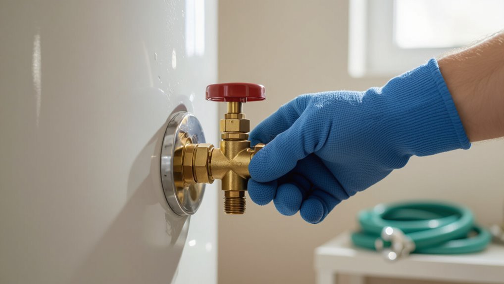
A pressure relief valve protects home plumbing and heating systems by releasing excess pressure to prevent bursts or equipment damage.
Manual opening is sometimes required during maintenance, after thermal expansion in water heaters, or when a valve fails to seat properly.
Improper operation can cause scalding, water damage, or system overpressure, so correct procedure and precautions are essential.
Purpose of a pressure relief valve in home systems
Several home systems rely on pressure relief valves to prevent dangerous overpressure by automatically releasing excess steam or water when set limits are exceeded.
Their purpose is safeguarding boilers, water heaters and piping from rupture, corrosion and unsafe pressure.
Understanding how to open a pressure relief valve is part of safe maintenance knowledge, enabling controlled depressurization for inspection, repair or controlled draining.
Common scenarios requiring manual opening
When might someone need to open a pressure relief valve manually?
Typical reasons include relieving trapped pressure during maintenance, verifying valve operation, draining excess pressure after system repairs, or freeing a stuck actuator.
Technicians may open valves to diagnose system faults or equalize pressure before component replacement.
Homeowners might do so following heater servicing or unexpected pressure buildup indicated by gauges.
Safety risks of improper operation
Having identified common reasons for manual valve operation, it is important to understand the safety risks that follow improper handling.
Incorrect or premature opening can cause scalding steam, sudden pressure loss, equipment damage, or explosive failure. Bypassing procedures risks release of toxic fluids and environmental contamination.
Untrained attempts increase injury likelihood; adherence to protocols, proper PPE, and isolation of systems mitigate these hazards.
Quick Safety Checklist Before You Begin
Before opening a pressure relief valve, the operator checks that required PPE and tools are on hand.
System pressure and isolation points are verified to confirm the valve can be operated safely.
Occupants are notified and related equipment is shut down or isolated to prevent unintended activation.
Personal protective equipment (PPE) and tools required
A concise PPE and tools checklist helps guarantee safe, controlled opening of a pressure relief valve.
Protective gear and proper implements minimize injury and environmental release. Essential items include:
- Hard hat, safety goggles, face shield, and chemical-resistant gloves.
- Flame-resistant clothing and steel-toe boots.
- Adjustable wrench set, valve key, and torque wrench.
- Leak detection spray, absorbent pads, and a pressure-rated relief cap.
Verifying system pressure and isolation points
Verification of system pressure and isolation points is essential to prevent accidental discharge or equipment damage; personnel must confirm monitored pressure readings and physically identify all upstream and downstream isolation valves. They should record values, tag isolation locations, and verify zero-energy where applicable before proceeding.
| Component | Location | Status |
|---|---|---|
| Gauge | Boiler feed | Checked |
| Valve A | Upstream | Closed |
| Valve B | Downstream | Closed |
| Tag | Relief line | Attached |
Notifying occupants and shutting down related equipment
Notify all nearby personnel and occupants of the planned relief valve operation and secure or shut down any equipment that could be affected by pressure changes, including pumps, compressors, and electrical systems tied to the relief line.
Establish clear communication channels, post warning signs, and isolate downstream systems.
Verify lockout/tagout, confirm standby personnel are positioned safely, and document shutdowns before proceeding with valve operation.
Identifying the Correct Pressure Relief Valve
The next step is identifying which pressure relief valve applies to the system at hand, such as those on water heaters, boilers, air compressors, or propane tanks.
The technician should locate the valve, read any markings or labels, and confirm its rated pressure and orientation.
Finally, they must inspect for serviceability by checking for corrosion, signs of being fused or sealed, and any manufacturer instructions that restrict operation.
Types of relief valves found in homes (water heater, boiler, air compressor, propane tank)
Homes contain several types of pressure relief valves—each designed for a specific system and marked by distinct size, location, and outlet style—so identifying the correct one is essential before any inspection or operation.
Water heaters use temperature-pressure (T&P) valves; boilers employ spring-loaded safety valves or relief valves; air compressors use pop-off or unloader valves; propane tanks have OPD or pressure relief devices.
Locating the valve and understanding markings or labels
Finding a pressure relief valve begins with a systematic visual search of the appliance and its immediate piping: valves are typically mounted near the top or on the side of water heaters, on the steam or hot-water outlet of boilers, on the outlet or tank head of air compressors, and on the dome or service opening of propane cylinders.
Identify stamped set pressure, flow direction arrows, manufacturer, model, and serial numbers; confirm access and any nearby isolation or discharge piping.
How to determine if the valve is serviceable or fused/sealed
After locating the valve and noting its markings, inspection shifts to whether the device can be operated or is fused/sealed.
The inspector checks for tamper seals, paint, corrosion, locked levers, or welded components.
Gentle manual actuation, with system depressurization, reveals mobility.
If resistance persists or alterations are present, tag as fused/sealed and arrange professional service before attempting operation.
Step-by-Step Procedure to Open a Pressure Relief Valve Safely
The procedure begins by reducing system load and isolating the affected component, then confirming pressure readings and allowing any required cool-down.
Next, a safe discharge path and drainage are established before manually actuating the valve using the appropriate lever, lift ring, or cap technique.
Finally, pressure drop and release flow are monitored until readings stabilize.
Step 1 Reduce system load and isolate the component
Begin by reducing system pressure and isolating the relief valve’s connected section to create a safe work environment.
Close upstream supply and downstream valves, tag and lock isolation points, and relieve trapped fluid using designated drains or vents.
Verify isolation visually and with valve position indicators.
Confirm energized equipment is de-energized per lockout/tagout procedures before proceeding to inspection or service.
Step 2 Confirm pressure readings and allow cool-down if needed
At this stage, personnel must verify that all pressure indications at the valve and within the isolated section are at or below safe levels using calibrated gauges or portable pressure probes. Readings should be recorded; if temperature or pressure remains elevated, allow controlled cool-down and monitor until stable. Proceed only when values meet permitted limits.
| Parameter | Action |
|---|---|
| Pressure | Record |
| Temperature | Monitor |
| Time | Wait |
| Status | Confirm |
Step 3 Position safe discharge path and drainage
Positioning a safe discharge path and drainage requires identification and preparation of the route that will carry relieved fluid away from personnel, equipment, and sensitive areas.
The designated path should slope to a suitable containment, use rated piping or hoses, avoid electrical panels, and be anchored to prevent whip.
Place warning signage, establish exclusion zones, and confirm downstream drains or collection tanks can handle expected flow and temperature.
Step 4 Manually actuate the valve (technique for lever, lift ring, or cap)
With the discharge path secured and exclusion zones established, attention turns to manually actuating the relief device using the lever, lift ring, or cap.
The operator dons gloves, positions body clear of outlet, and applies a controlled, steady motion to lift or rotate the actuator.
Avoid sudden jerks; verify tactile feedback that the valve opens.
Release slowly if resistance or vibration appears.
Step 5 Monitor pressure drop and release flow until stable
Once the valve begins to move, the operator observes the pressure gauge and flow indicators continuously, noting the rate and magnitude of pressure drop while watching for erratic readings or unexpected spikes.
They allow controlled release until readings plateau, maintaining safe distance and communication with team members.
Any sudden oscillation or abnormal flow prompts immediate cessation and assessment before resuming controlled venting.
Step 6 Reseat the valve and check for proper closure
Lower the actuator slowly and align the valve disc with its seat using visual and tactile checks; this guarantees a controlled closure while minimizing hydraulic shock or binding.
Once seated, confirm sealing by applying low system pressure and observing for leaks or seepage.
Tighten fasteners to specified torque, verify actuator return to neutral, and document closure status and any deviations for follow-up maintenance.
Special Procedures for Common Systems
Guidance for opening relief valves must be adapted to the system type, since water heaters, boilers, air compressors, propane/LP tanks, and radiant closed-loop systems each pose distinct hazards and configurations.
Specific steps include temperature-and-pressure (T&P) valve procedures for heaters, controlled venting for compressors, strict precautions for gas-containing tanks, and isolation checks for radiant or closed-loop circuits.
The following section outlines concise, system-specific precautions and actions.
Water heater or boiler T&P valve specific steps
When dealing with a water heater or boiler, the temperature-and-pressure (T&P) relief valve requires specific precautions due to system pressure, hot water discharge, and location of drain lines.
Isolate power and gas, allow cooling, and relieve system pressure per manufacturer instructions.
Position a suitable heat-resistant hose to a safe drain, don protective gear, open the valve slowly to test function, then fully close and inspect for leaks.
Air compressor safety release procedure
Begin by shutting off the compressor motor and closing the inlet valve to isolate the air source.
Then bleed the remaining pressure from the tank using the manufacturer-approved drain or purge valve.
Guarantee all downstream equipment is isolated and pneumatic tools are disconnected before opening any safety or relief devices.
Inspect the relief valve for damage, wear personal protective equipment, slowly crack the valve to confirm operation, and record pressure readings.
Propane/LP tank relief valve precautions
Why is extra caution required around propane/LP tank relief valves?
Propane relief valves vent flammable gas under pressure; improper manipulation risks leaks, ignition, frostbite from rapid gas expansion, and regulator damage.
Only trained personnel should operate or depressurize tanks.
Guarantee open-air ventilation, eliminate ignition sources, use appropriate PPE, follow utility or supplier protocols, and notify authorities if uncontrolled venting occurs.
Radiant heating and closed-loop systems
After addressing the unique hazards of propane relief valves, attention shifts to radiant heating and closed-loop hydronic systems, which pose different risks such as pressurization, water contamination, thermal shock, and hidden leaks.
Technicians should isolate zones, relieve pressure slowly, collect and test expelled fluid for inhibitors or contaminants, monitor temperatures, and inspect for corrosion or failed check valves before resealing the system.
How to Read Pressure and Temperature Data During Release
The operator should verify that gauges and digital monitors are properly calibrated and read them according to manufacturer guidance before and during the release.
Trends in pressure and temperature must be tracked in real time to determine whether the bleed is progressing as planned and to identify the point at which releasing should be halted.
Sudden deviations, persistent high readings, or unexpected temperature changes should prompt immediate shutdown and investigation for underlying system faults.
Using gauges and digital monitors correctly
Accurate interpretation of pressure and temperature instruments is essential to safe valve operation; operators should rely on calibrated gauges and validated digital monitors to track real-time conditions during a release.
Read instruments at eye level, note units and ranges, confirm alarm setpoints, and log values.
Verify sensor connections, watch for lag or spikes, and cross-check a mechanical gauge with a digital readout before adjusting the valve.
Interpreting pressure trends and when to stop releasing
Monitor pressure and temperature trends continuously during a release to detect slowing rates, inflection points, or unexpected reversals that indicate changing system dynamics.
The operator notes rate-of-change, stabilization near setpoint, and temperature coupling.
Stop releasing when pressure approaches safe thresholds, rate-of-drop diminishes, or readings oscillate.
Record values, time stamps, and actions taken for post-event review and verification.
When readings indicate a deeper problem
If pressure or temperature trends deviate from expected declines—showing sudden spikes, prolonged plateaus, or divergent sensor readings—it may signal a deeper system fault rather than a normal settling.
The operator should stop release, isolate the vessel, secure ignition sources, and notify qualified maintenance. Record timestamps, sensor values, and valve positions.
Avoid restarting release until diagnostics, leak tests, and component inspections confirm safe operation.
Signs of Valve Failure and When to Replace Instead of Open
Common indicators of valve failure include sticking, persistent leakage, visible corrosion, and impaired movement that prevent a proper seal.
Thermal fusion, blockages in the inlet or discharge path, or deformation from overheating are signs that the valve cannot function reliably.
Immediate replacement is warranted for thermally fused, severely corroded, or mechanically jammed valves, while minor leaks or marginal sticking may be addressed temporarily with controlled measures and prompt scheduling of a replacement.
Symptoms of a stuck, leaking, or corroded valve
Signs that a pressure relief valve is failing include visible leaks, a valve that remains stuck open or closed, corroded or pitted surfaces, unusual noises during operation, and pressure readings that consistently deviate from set points.
Other symptoms include dripping at the outlet, mineral buildup, slow response to pressure changes, vibration during cycling, and recurring system pressure excursions indicating compromised sealing or weakened spring tension.
When a valve is thermally fused or blocked
Problems such as persistent leaks, corrosion, or a valve that sticks intermittently can escalate into more severe conditions where the valve becomes thermally fused to its seat or blocked by deposits.
In such cases the relief mechanism fails to move, flow is impeded, and overheating risks increase.
Visible mineral buildup, charred metal, or immobility despite proper actuation indicate irreversible damage requiring removal and replacement rather than forced opening.
Criteria for immediate replacement vs temporary measures
When a relief valve shows evidence of structural compromise or persistent malfunction, immediate replacement should be prioritized over temporary fixes.
Corrosion, cracks, spring failure, seating damage, recurrent leaking after adjustment, or loss of calibration indicate end‑of‑service.
Temporary measures (isolating, depressurizing, or tagging out) are acceptable only for short delays until a certified replacement is installed to restore reliable, code‑compliant protection.
Post-Operation Checks and Follow-Up
After operation, the valve seating should be inspected and the system leak-tested to confirm proper closure.
The system must then be restored to normal configuration and pressurization should be resumed gradually while monitoring for abnormalities.
The action should be documented and a professional inspection scheduled if any issues or uncertainties remain.
Inspecting valve seating and leak testing
A careful inspection of the valve seating and a controlled leak test are essential steps following a pressure relief operation to confirm proper reseating and system integrity. Technician visually examines seat, cleans debris, and verifies alignment. Perform low-pressure leak test, monitor for bubbles or pressure drift, document findings, and tag valve for service if leakage persists.
| Step | Action |
|---|---|
| 1 | Visual inspect |
| 2 | Clean seat |
| 3 | Align components |
| 4 | Leak test |
| 5 | Document results |
Restoring system to normal operation and gradual pressurization
Restore system controls and gradually reintroduce pressure following verification that the relief valve reseated properly and leak testing shows no persistent leakage.
Open isolation valves slowly, monitoring gauges and system indicators for normal readings.
Observe for unusual noises, vibrations, or temperature changes.
If parameters remain stable, return to normal operating pressures incrementally.
Maintain close observation for a defined stabilization period before declaring the system fully operational.
Documenting the action and scheduling professional inspection
Once system parameters have stabilized and normal operation is confirmed, the incident and all corrective steps should be recorded concisely in the maintenance log. Entries must include timestamps, valve ID, actions taken, and operator initials. Schedule a professional inspection if any anomaly or repeated relief occurs. Review and attach photos and measurements for the inspector.
| Date | Valve ID | Action |
|---|---|---|
| 2026-09-11 | PRV-01 | Opened, bled, reset |
| 2026-09-11 | PRV-01 | Photos attached, inspector scheduled |
Common Mistakes and How to Avoid Them
Common errors during pressure relief valve operations include opening the valve while the system is still hot, standing in the discharge path, using improper tools, and failing to isolate or depressurize connected equipment.
Each mistake increases the risk of burns, impact injuries, or uncontrolled releases. Identifying these hazards and following strict isolation, cooling, positioning, and tool procedures prevents most incidents.
Opening under high temperature without cooling
Opening a pressure relief valve while the system remains at elevated temperature risks rapid depressurization, steam or hot fluid discharge, and serious burns or equipment damage.
Operators should allow controlled cool-down, vent per manufacturer procedures, verify temperature and pressure readings, use thermal insulation and remote monitoring, and wait until safe thresholds are met.
Ignoring cooling procedures increases injury and equipment failure risk.
Standing in the discharge path or using incorrect tools
After ensuring the system has cooled to safe levels, attention must turn to personal positioning and tool selection when accessing a pressure relief valve.
Standing in the discharge path exposes personnel to scalding fluid or sudden high-velocity discharge.
Use appropriate, insulated tools and long-handled wrenches designed for the valve.
Maintain a clear escape route and stand to the side, out of the outlet trajectory.
Failing to isolate or depressurize connected equipment
Failing to isolate or depressurize equipment connected to a relief valve can allow trapped pressure to release unexpectedly into the work area, creating a severe hazard.
Technicians should lock out and tag isolation valves, vent downstream lines, and confirm zero pressure with calibrated gauges.
Verify isolation visually and by testing before opening the valve.
Document steps and communicate status to all personnel involved.
When to Call a Professional
When pressure relief valves involve high-pressure systems, fuel-related components, or unclear causes of malfunction, a qualified professional should be engaged.
Legal and code requirements for boilers and gas appliances can mandate licensed technicians and proper documentation.
Homeowners are advised to verify credentials, insurance, and references when selecting a technician.
High-pressure systems, fuel-related valves, and uncertain diagnoses
Recognize that high-pressure systems and fuel-related valves present acute hazards that exceed routine maintenance risks and often require specialized tools and training; if pressure levels are unknown, service history is incomplete, visible damage exists, or fuel is involved, a qualified technician should be contacted rather than attempting further intervention.
| Risk | Indicator | Action |
|---|---|---|
| High pressure | Readings unstable | Stop, call pro |
| Fuel valve | Smell/leak | Evacuate, call pro |
| Unknown fault | Intermittent issue | Diagnose professionally |
Legal and code considerations for boilers and gas appliances
After noting that unknown pressures, fuel involvement, or visible damage warrant professional intervention, attention must also be paid to legal and code requirements governing boilers and gas appliances.
Local building codes, manufacturer instructions, and licensing laws often mandate certified technicians for repairs, pressure testing, or modifications.
Noncompliance risks safety, insurance denial, and fines; consult authorities having jurisdiction before proceeding.
Finding and vetting qualified technicians
Many homeowners will need a qualified technician for pressure-relief valve issues that exceed routine checks or involve uncertain pressures, gas, or apparent damage.
A professional assessment guarantees safety, proper diagnosis, and code-compliant repairs.
Vet candidates for credentials, experience, and insurance before hiring.
- Confirm licenses and certifications.
- Check references and recent work.
- Verify liability insurance.
- Obtain a written estimate and warranty.
Preventive Maintenance to Reduce Emergency Valve Operations
Preventive maintenance focuses on scheduled inspections that check for corrosion, seat wear, leaks, and proper set pressure.
Routine cleaning, periodic exercising, and timely replacement of relief valves help prevent unplanned operations.
Accurate record-keeping of findings and trends enables early identification of signs that predict failure.
Regular inspection schedules and what to look for
A consistent inspection schedule is essential to confirm pressure relief valves remain reliable and to minimize emergency operations.
Inspections should occur at manufacturer-recommended intervals and after abnormal events. Technicians check for corrosion, leaks, seat damage, improper set pressure, visible deformation, and obstruction.
Records must document date, findings, corrective actions, and responsible personnel to confirm traceability and timely follow-up.
Cleaning, exercising, and replacing relief valves proactively
Schedule routine cleaning, exercising, and timely replacement of relief valves to maintain performance and reduce the likelihood of emergency operations.
Technicians should remove debris, inspect seating surfaces, and cycle valves per manufacturer intervals to prevent sticking.
Replace corroded, worn, or tested-out units before failure.
Use compatible parts, follow torque/spec guidelines, and confirm proper reseating and set pressure after maintenance.
Record-keeping and signs that predict failure
Consistent record-keeping and early identification of deterioration signs are essential to predict relief valve failure and minimize emergency operations.
Logs should note installation dates, test results, lift counts, setpoint deviations, corrosion, and leak history.
Trend analysis detects progressive drift, sticking, or seat wear.
Scheduled reviews trigger calibration, cleaning, or replacement before malfunction.
Clear documentation supports compliance and informed maintenance decisions.
Quick Reference: Tools, PPE, and Safety Distances
Several essential items and precautions are required before attempting to open a pressure relief valve: the correct tools, appropriate personal protective equipment (PPE), and clearly established safety distances.
Personnel should verify tool condition, don PPE, and mark exclusion zones. Maintain communication and emergency readiness.
- Calibrated wrench set and valve gear
- Eye, face, hearing protection
- Flame-resistant clothing, gloves, boots
- 3–10 m exclusion zone depending on pressure rating
Conclusion
A final sweep of caution wraps the guide like a lighthouse beam over a stormy sea: when opening a pressure relief valve, measured steps, proper PPE, and correct identification keep risk at bay. Homeowners and technicians should follow the checklist, use the right tools, and observe system-specific procedures. Avoid shortcuts, know limitations, and call a professional if uncertain. Regular maintenance reduces surprises and makes future operations safer and more predictable.