How to Install an O-Ring on a Pipeline: Step-by-Step Guide for a Leak-Free Seal
To install an O-ring on a pipeline for a leak-free seal, start by selecting the correct material and size for your application. Clean and inspect the gland and mating surfaces thoroughly. Ensure the system is depressurized, then gently stretch the O-ring and seat it into a clean groove or slide it onto a shaft with even pressure. If working with high pressure, consider adding backup rings for added security. Finally, conduct follow-up pressure testing and routine inspections to confirm the integrity of the seal. For any specialized techniques or troubleshooting, refer to detailed guides.
What an O-Ring Is and Why Proper Installation Matters
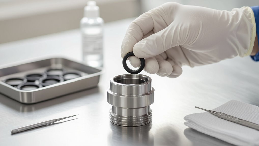
An O-ring is a circular elastomer seal used in pipelines to prevent fluid escape by sitting in a gland and compressing between mating surfaces.
Common materials—such as NBR, EPDM, FKM, and PTFE—are chosen for compatibility with specific fluids and temperature ranges.
Incorrect installation can cause leaks, component failure, and significant safety and environmental hazards.
Definition and function of O-rings in pipelines
O-rings are simple, circular elastomeric seals that prevent fluid or gas leakage at pipeline joints and fittings. They compress between mating surfaces to maintain pressure integrity and accommodate slight misalignment or movement.
Correct seating, lubrication, and damage-free installation are essential; instructions on how to install o-ring on pipeline emphasize proper sizing, groove fit, and inspection to guarantee a durable, leak-free seal.
Common materials and compatibility with fluids and temperatures
Material selection determines an O-ring’s performance and service life in any piping system. Selection depends on chemical compatibility, temperature range, and hardness. Common materials include NBR for oils, EPDM for water/steam, FKM for fuels/high heat, and silicone for low-temperature flexibility. Reference material charts and fluid lists when specifying seals to guarantee longevity and proper function.
| Material | Typical Use |
|---|---|
| NBR | Oils, fuels |
| EPDM | Water, steam |
| FKM | Fuels, high heat |
| Silicone | Low temp flexibility |
Consequences of improper O-ring installation (leaks, failures, safety risks)
When installed incorrectly, an O-ring can compromise a pipeline’s seal integrity and lead to leaks, pressure loss, or sudden failure.
Consequences include fluid contamination, equipment corrosion, environmental release, and costly downtime.
Improper seating, nicks, wrong size, or incompatible material accelerate wear and extrusion.
Personnel face slip, fire, or exposure hazards.
Regular inspection and correct installation mitigate these risks.
Quick Overview Leak-Free O-Ring Installation in One Paragraph
Begin by ensuring the groove and mating surfaces are clean, dry, and free of burrs or sharp edges; select the correct O-ring size and material, inspect for damage, lightly lubricate compatible surfaces, seat the O-ring evenly without twisting, verify proper groove fit and compression, reassemble carefully, and perform a pressure or leak test to confirm a reliable, leak-free seal before returning the pipeline to service.
Tools and Materials Needed Before You Start
Before beginning, a concise inventory of tools and materials guarantees a smooth O-ring installation on a pipeline.
Important items include:
- Recommended basic tools and optional specialty equipment
- Measurement tools and sizing charts to choose the correct O-ring size
- Material selection guidance for compatibility with pressure, temperature, and fluids
The next section will explain how to use these items to prepare the joint and select the right O-ring.
Recommended tools and optional specialty equipment
A concise kit of basic hand tools, lubrication, and measurement devices guarantees the O-ring can be fitted correctly and maintained. Recommended items include torque wrenches, soft-jawed pliers, calibrated calipers, O-ring lubricant compatible with system fluids, and lint-free wipes.
Optional specialty equipment improves efficiency and reliability:
- Vacuum chamber for leak testing
- Ultrasonic cleaner for groove prep
- Torque-angle monitor for repeatable fastenings
How to choose the correct O-ring size and material
Selecting the correct O-ring size and material requires matching dimensional tolerances and chemical/mechanical compatibility to the pipeline’s operating conditions—pressure, temperature range, media, and joint geometry—so the seal will maintain integrity without premature wear or failure. Use measurements, fluid compatibility charts, and hardness (durometer) selection; verify gland fit and extrusion gaps.
| Criterion | Check |
|---|---|
| Size | ID/CS/CS tolerance |
| Material | Chemical resistance |
| Hardness | Durometer rating |
| Temperature | Operating range |
| Pressure | Burst/extrusion limit |
Pre-Installation Inspection and Preparation
Before installing an O-ring, the inspector examines pipeline components and grooves for damage, corrosion, or debris and measures gland dimensions to confirm proper O-ring fit.
Cleaning of pipe ends and sealing surfaces is performed with appropriate solvents and lint-free wipes to guarantee a contaminant-free contact area.
Recommended lubricants and anti-seize compounds are selected for material compatibility and avoided when they could swell or degrade the O-ring.
Inspecting the pipeline components and grooves for damage or debris
Inspecting pipeline components and O-ring grooves requires careful visual and tactile examination to identify cuts, corrosion, burrs, swelling, or trapped debris that could compromise seal integrity.
The inspector documents defects, cleans residues, and flags parts for repair or replacement.
Recommendations include:
- Remove visible debris and corrosion with appropriate non-abrasive tools.
- Check for sharp edges or burrs; deburr as needed.
- Verify surfaces are dry and contaminant-free.
Measuring gland dimensions and verifying O-ring fit
Accurate gland measurements are essential to guarantee an O-ring will sit properly and form a reliable seal without overstress or extrusion.
The inspector records groove width, depth, and diameter, then selects an O-ring whose cross-section and stretch match specifications.
Fit verification uses compression and squeeze calculations plus dimensional tolerances to confirm correct gland fill.
- Measure groove geometry
- Compare O-ring spec
- Validate clearances
Cleaning procedures for pipe ends and sealing surfaces
Prepare pipe ends and sealing surfaces by removing all debris, corrosion, paint, welding slag, oils, and moisture that could compromise O-ring seating or promote leaks.
Inspect for nicks, burrs, or pits; record defects. Clean with approved solvents, then dry and verify cleanliness visually and with lint-free wipes.
- Mechanical removal of scale/burrs
- Solvent degrease and rinse
- Final dry and inspection
Lubricants and anti-seize compounds: what to use and what to avoid
With clean, defect-free pipe ends confirmed, attention turns to selecting and applying lubricants and anti-seize compounds that protect O-rings and mating surfaces without compromising material compatibility or seal performance.
Use silicone- or PTFE-based lubricants approved for the specific elastomer; avoid petroleum oils, solvents, and incompatible greases.
Apply sparingly to seating surfaces and threads; wipe excess to prevent contamination and swelling.
Step-by-Step O-Ring Installation Procedure
The following section outlines a concise, sequential procedure for installing O-rings on pipeline components, beginning with safety measures and isolating the line.
It then addresses O-ring preparation, techniques for fitting onto straight pipes and into grooves or flanges, and the use of installation tools and protective sleeves.
Each step emphasizes correct handling to prevent damage and guarantee a reliable seal.
Step 1 Safety precautions and isolating the pipeline
Safety is paramount: before any work begins, personnel must confirm the pipeline is fully depressurized, isolated, and locked out to prevent accidental flow or pressurization.
Personnel should verify permits, atmosphere, and PPE.
Follow these steps:
- Close and lock isolation valves; tag out.
- Bleed and vent residual pressure; verify with gauges.
- Test for hazardous atmospheres; monitor continuously.
Step 2 Preparing the O-ring (stretching, conditioning)
After isolation and atmosphere checks confirm a safe work zone, attention turns to preparing the O-ring for installation. The O-ring is inspected, cleaned, and conditioned to the ambient temperature before use.
- Inspect for cuts, nicks, or distortion.
- Clean with compatible solvent and lint-free cloth.
- Condition by gentle stretching and resting to relieve memory and guarantee proper seating.
Step 3 Installing the O-ring onto straight pipes or shafts
Begin by aligning the conditioned O-ring with the pipe or shaft, ensuring the groove and mating surfaces are free of debris and lubricated with a compatible, thin film lubricant.
Then slide the O-ring evenly onto the shaft using steady pressure, rotating it as needed to prevent twisting or pinching until it seats fully in the groove.
- Verify size and orientation.
- Use steady, even motion.
- Inspect seating and return elasticity.
Step 4 Installing O-rings into grooves and flanges
With the O-ring seated on the shaft or pipe, attention turns to installing O-rings into grooves and flanges, which requires careful alignment of the seal with the mating groove profile and flange faces.
Verify groove cleanliness and dimensions. Lightly lubricate compatible compound. Seat ring evenly, avoiding twists.
- Align groove and O-ring
- Press uniformly into groove
- Inspect for pinches and gaps
Step 5 Using installation tools and protective sleeves
Select and use proper installation tools and protective sleeves to prevent O-ring damage during assembly. The installer should employ soft-tip picks, tapered mandrels, and polymer sleeves to avoid nicks or overstretching.
Follow protection steps:
- Inspect tool tips and sleeves for debris.
- Lubricate sleeve and O-ring lightly per specification.
- Slide sleeve over seal, install O-ring, then remove sleeve carefully.
Step 6 Reassembling joints and applying correct torque
After the O-ring and mating surfaces are verified clean and correctly positioned, the joint should be reassembled in a controlled sequence while applying the specified torque pattern to fasteners.
Reassembly must avoid distortion and maintain gasket compression. Use calibrated tools, follow manufacturer torque values, and document steps.
- Sequence bolts evenly
- Apply torque in stages
- Verify final torque readings
Step 7 Pressure testing and leak checking after installation
Begin pressure testing once mechanical assembly is complete and documented, using the specified test medium, pressure levels, and procedures from the equipment manufacturer or applicable code.
Monitor for leaks, hold pressure for required duration, and record results. If leaks occur, depressurize, inspect O-ring seating and surfaces, then repair and retest.
- Pressure ramp and hold
- External visual inspection
- Record and certify results
Common Installation Problems and How to Fix Them
Common installation problems include twisting, rolling, or pinching of the O-ring during fitting, which can be prevented by proper lubrication, gradual seating, and use of installation tools to control alignment.
Cuts, nicks, and abrasions should be inspected visually and by touch; any O-ring with damage or compromised cross-section must be replaced.
Incorrect sizing or chemical incompatibility is diagnosed by leakage patterns, swelling, or rapid hardening, and is corrected by selecting the proper size and material compatible with the conveyed fluid.
Twisting, rolling, or pinching during installation causes and corrections
Twisting, rolling, or pinching an O‑ring during installation can compromise seal integrity, shorten service life, and cause immediate leaks.
Causes include misaligned grooves, improper lubrication, forcing over sharp edges, or using incorrect tooling.
Correction requires removing and inspecting the O‑ring, cleaning and chamfering mating parts, applying appropriate lubricant, seating the O‑ring evenly, and using proper installation tools and techniques to avoid deformation.
Cuts, nicks, and abrasions on O-rings identification and replacement criteria
Inspect O‑rings carefully for cuts, nicks, and abrasions, since these surface damages compromise sealing surfaces and often indicate the need for replacement.
Visual and tactile inspection under good light reveals shallow scrapes, linear cuts, or rubbed areas.
Any damage breaking the elastomer continuity, deep gouges, or localized thinning warrants immediate replacement; minor surface scuffs may be monitored but not relied upon for long-term service.
Sizing errors and chemical incompatibility diagnosis and corrective actions
Diagnose sizing errors and chemical incompatibility by systematically comparing the installed O‑ring dimensions and material to the application requirements and service fluid characteristics.
Measure cross‑section, inner diameter and gland fit; verify durometer and compound.
Inspect for swelling, softening, or cracking indicating chemical attack.
Correct by selecting proper size, correcting gland geometry, or switching to chemically compatible elastomer (e.g., Viton, EPDM, FKM) and retest.
Best Practices to Ensure Long-Term Leak-Free Seals
Proper storage and careful handling preserve O-ring material properties and prevent premature failure.
Regular inspections and predictive maintenance schedules identify wear before leaks occur.
Accurate documentation of replacements and inspection results supports traceability and continuous improvement.
Storage and handling recommendations for O-rings
Several simple storage and handling measures greatly extend O-ring life and preserve sealing performance.
Store in cool, dark, dry conditions away from ozone sources and solvents.
Handle with clean gloves and soft tools to avoid nicks or stretch.
Rotate stock to use oldest first; avoid stacking heavy loads.
- Temperature control
- Clean handling
- FIFO inventory management
Routine inspection schedules and predictive maintenance tips
Following careful storage and handling, routine inspection schedules and predictive maintenance practices keep O-rings performing reliably over their service life.
Inspections should verify compression set, cuts, and chemical attack; replace before erosion compromises sealing. Predictive methods include vibration analysis and infrared thermography to detect anomalies.
- Monthly visual and torque checks
- Quarterly non-destructive testing
- Condition-based replacements guided by trend data
Documentation and record-keeping for seal replacements
Accurate, accessible records of every seal replacement provide the foundation for consistent, long-term leak prevention.
Documentation should include date, location, O-ring material and size, lubricant type, torque values, installer identity, inspection findings, and test results.
Digital logs with versioning and searchable fields enable trend analysis and regulatory compliance.
Retain records per retention policy and guarantee secure backups and controlled access for audit readiness.
Special Scenarios and Advanced Considerations
For installations subject to extreme pressure or temperature, material selection and gland design must be reevaluated to maintain seal integrity.
Techniques and tooling differ when placing O-rings in confined spaces or underwater, requiring corrosion-resistant components and controlled installation methods.
Where extrusion or displacement risk exists, backup rings, spacers, and secondary seals are prescribed to preserve O-ring performance.
High-pressure and high-temperature pipeline installations
Installations in high-pressure, high-temperature pipelines demand specialized O-ring selection, precise installation techniques, and verification steps that exceed standard practice. Materials must resist thermal aging and extrusion while installation tolerances and equipment account for differential expansion, pressure cycling, and limited access for inspection.
Qualified elastomers, backup rings, controlled lubrication, thermal relief, torque-limited fasteners, and post-installation leak and pressure-hold testing guarantee long-term integrity.
Installing O-rings in confined or underwater environments
Many confined-space and underwater O-ring installs demand adapted tools, altered procedures, and heightened safety controls to address limited access, poor visibility, fluid contamination, and diver or technician ergonomics.
Technicians must use corrosion-resistant tools, low-shedding lubricants, and lighting aids; verify compatibility with surrounding fluids; employ tethering and remote manipulation where possible; and follow confined-space permits, atmospheric monitoring, and dive protocols to mitigate risk and guarantee seal integrity.
Using backup rings, spacers, and secondary seals
Confined-space and underwater installs sometimes expose O-rings to pressures, extrusion gaps, or chemical exposures that surpass the O-ring’s capability alone; in those cases, backup rings, spacers, and secondary seals are used to preserve seal geometry and prevent material deformation or migration.
- Backup rings: prevent extrusion at high pressure.
- Spacers: maintain alignment and compression.
- Secondary seals: provide chemical or redundant protection.
Comparison: O-Rings vs. Alternative Seals for Pipelines
When selecting between O-rings, gaskets, and mechanical seals, the decision hinges on pressure, movement, and installation space. O-rings typically suit dynamic joints with limited clearance and moderate to high pressure, while gaskets fit flat flange faces and mechanical seals handle very high pressures or shaft sealing. The table below summarizes typical choices and trade-offs.
| Seal Type | Best Use Case | Key Advantage |
|---|---|---|
| O‑Ring | Dynamic joints, confined grooves | Compact, reliable under pressure |
| Gasket | Flanged, static joints | Conforms to surface irregularities |
| Mechanical Seal | Rotating shafts, extreme pressure | Handles high pressure and speed |
| When to choose | O‑ring if limited space and movement present | Prefer O‑ring for compact, pressurized connections |
When to choose an O-ring over gaskets or mechanical seals
How should an engineer decide between an O-ring, a gasket, or a mechanical seal for a pipeline application?
An O-ring suits compact joints, dynamic shafts, moderate pressures, and when chemical compatibility and temperature range match elastomer properties.
Choose gaskets for irregular flanges, larger surface areas, or low-compression joints.
Use mechanical seals for high-speed rotating equipment, extreme pressure, or when elastomers cannot meet wear and leakage demands.
Troubleshooting Checklist for Post-Installation Leaks
A concise checklist guides the technician through resolving post-installation leaks with clear steps and escalation points.
- Perform diagnostic steps to isolate the leak source.
- Record measurements (pressure, gap, and deformation) to verify seal integrity.
- Escalate to a specialist when measurements or repairs exceed safe limits.
Diagnostic steps, measurements, and when to call a specialist
Begin by isolating the leak and documenting its location, size, and operating conditions; this establishes a clear baseline for diagnostics and prevents wasted effort on transient or unrelated drips.
Measure pressure, temperature, and differential across the seal, inspect O-ring seating and groove dimensions, and check material compatibility.
If leaks persist after sealing, visible damage, or complex system interfaces exist, engage a specialist.
Quick Reference: O-Ring Size Selection and Material Chart
Several concise tables and guidelines help technicians select the correct O-ring size and material for pipeline applications, balancing seal dimensions, tolerances, and chemical/temperature compatibility. A quick reference pairs common bore sizes, recommended materials, and operating ranges for rapid selection and verification.
| Bore Size | Material | Temp/Chem Range |
|---|---|---|
| 1″ | Nitrile (Buna-N) | -40–120°C; oils |
| 2″ | EPDM | -50–150°C; water, steam |
| 3″ | Viton | -20–200°C; fuels, acids |
Conclusion
Proper O‑ring installation prevents costly pipeline failures and extends component life. Studies show that improper sealing causes about 36% of small-pipeline leaks, underscoring attention to fit and surface condition. Following inspection, lubrication, correct sizing, and careful seating dramatically reduces failure risk. For challenging environments, select compatible materials and consider backup rings or double O‑ring arrangements. Regular post‑installation checks and adherence to torque and pressure limits guarantee a reliable, leak‑free seal.