How to Disconnect the Gas Line From the Stove Safely: Step-By-Step Guide
To safely disconnect the gas line from your stove, follow these essential steps: First, ensure a qualified technician or trained homeowner is performing the task. Confirm the gas type and notify all occupants. Next, turn off both the appliance and service valves. Use a detector or soapy water to verify zero pressure in the line. After that, disconnect the flexible connector and immediately cap or plug the gas supply. Finally, conduct a pressure and leak test to ensure safety. Always have the proper tools, personal protective equipment (PPE), necessary permits, and documentation on hand.
How to Safely Disconnect the Gas Line from a Stove: Quick Overview
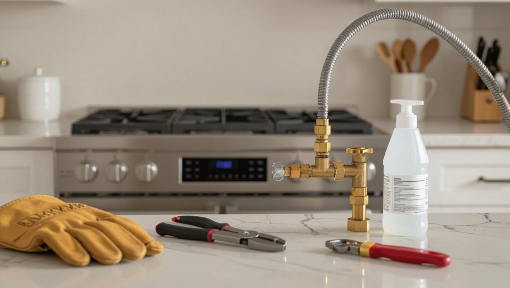
This task is appropriate for licensed gas technicians or experienced DIYers familiar with gas fittings; untrained individuals should not attempt it.
The primary safety outcome is to guarantee all gas flow is securely shut off and connections are leak-free before restoring service.
Expect the procedure to take roughly 15–45 minutes depending on access and whether fittings require replacement.
Who should (and should not) attempt this task
Who is suited to disconnect a stove gas line depends on training, experience, and access to proper tools and safety gear.
Certified gas technicians and experienced plumbers should handle how to disconnect the gas line from the stove.
Homeowners with formal training and adequate tools may proceed.
Untrained individuals, those uncomfortable with gas work, or without shutoff access should not attempt this and must hire professionals.
Required safety outcome and time estimate
After confirming qualifications and readiness to proceed, the required safety outcome is a fully isolated, gas-tight connection at the appliance inlet with no detectable leak and the house gas supply securely shut off.
Verification should include visual inspection of fittings, use of an approved gas sniffer or soapy water test, and confirmation that all burners remain unlit when the supply is re-energized.
Estimated duration: 30–60 minutes.
Tools, Materials, and Safety Equipment Needed
A clear list of hand tools and fittings is essential before beginning the procedure.
Appropriate safety gear and gas-monitoring devices should be identified and ready for use.
Common replacement parts and supply items to have on hand are also noted to prevent delays and guarantee a proper reconnection.
Tools list
Several essential items are required before attempting to disconnect a stove gas line: an adjustable wrench or appropriate-sized flare-nut wrench, pipe thread sealant rated for gas or approved gas-grade tape, a gas shutoff key or valve handle, leak-detection solution (soapy water or a commercially available checker), a bucket or rags for catching drips, and a flashlight.
- Adjustable or flare-nut wrench
- Gas-rated thread sealant/tape
- Leak-detection solution
- Bucket/rags and flashlight
Safety gear and monitoring devices
Proper protective gear and continuous monitoring devices are essential to minimize risk when disconnecting a stove gas line.
The technician should use approved respirator, flame-resistant gloves, eye protection, and long sleeves.
Portable gas detector and audible leak alarm provide continuous monitoring. Follow calibration and battery checks prior to work.
- Respirator
- Flame-resistant gloves
- Eye protection
- Portable gas detector
Replacement parts and supplies to have on hand
Technicians should assemble a concise kit of replacement parts, tools, and safety items before disconnecting a stove gas line to prevent delays and guarantee safe restoration.
Essential spares and supplies include fittings, sealant, and basic hand tools for quick repairs; portable leak detector and fire extinguisher; replacement flex connector; and thread sealant rated for gas.
Prompt availability minimizes risk and downtime.
- Spare flex connector
- Gas-rated thread sealant
- Adjustable wrenches and tubing cutters
- Portable gas leak detector and extinguisher
Preliminary Safety Checks Before You Begin
Before any work begins, the technician confirms the appliance uses the expected gas type and locates the household service shutoff.
Household members are notified and all ignition sources are disabled while ventilation and a checklist for controlling potential ignition points are established.
Finally, the procedure for reading and turning the main gas shutoff valve is reviewed so the supply can be closed safely.
Confirm gas type and service shutoff location
Which gas serves the appliance and where the shutoff lives are the two facts that must be verified before any work begins. The technician confirms propane versus natural gas and locates the appliance shutoff, house service valve, and meter. Record labels and photos for clarity. Check valve orientation and accessibility; plan for tools and clearance.
| Item | Location |
|---|---|
| Appliance valve | Behind stove |
| Service valve | Utility area |
| Meter | Exterior wall |
Notify household and disable ignition sources
With the gas type confirmed and shutoff locations recorded, the next step is to notify household members and remove ignition sources to reduce risk.
Inform everyone of planned work and enforce an exclusion zone.
Turn off pilot lights, extinguish open flames, unplug electrical devices near the stove, and avoid using lighters or matches.
Make certain smokers refrain from lighting inside until job completion.
Ventilation and ignition control checklist
Make certain immediate areas are well-ventilated and all potential ignition sources are controlled before any work begins.
The person should verify airflow, remove open flames, and prevent sparks.
Follow this concise checklist:
- Open windows and run exhaust fans.
- Turn off pilot lights and electric igniters.
- Remove flammable materials nearby.
- Use non-sparking tools and avoid wearing synthetic fabrics.
How to read and close the main gas shutoff valve
Locate the main gas shutoff valve and confirm its orientation before attempting any adjustments.
The reader checks whether the valve handle aligns with the pipe (open) or perpendicular (closed). If rotary, note slot direction.
Turn firmly but gently to closed position; use an adjustable wrench only if stuck.
Verify gas is off by testing appliances or using a gas detector, then proceed.
Step-by-Step Procedure to Disconnect a Gas Line from a Stove
The procedure begins with turning off the stove and the appliance gas valve, then isolating the household shutoff to remove any source of pressure.
Confirmation that gas is absent should be obtained with a gas detector or soapy water before loosening the connector or pipe fitting.
Once disconnected, the supply line must be immediately capped or plugged and checked for leaks.
Step 1 Turn off the stove and gas supply at the appliance
Before touching fittings, make certain the stove is off and the appliance shutoff valve at the connection is closed.
The person confirms all burners and oven controls read “off,” then extinguishes any pilot lights.
Ventilation is opened. A non-sparking flashlight may be used.
They check for the absence of gas odor near the appliance before proceeding to tools or disconnection steps.
Step 2 Isolate the gas supply at the household shutoff
Shut off the household gas at the main valve to completely isolate supply before any disconnection work begins.
The technician locates the meter or main shutoff, turns the valve perpendicular to the pipe, and secures it with a lock or tag if available.
Notify household members, record valve position, and avoid operating appliances until the line is verified safe.
Step 3 Verify the gas is off using a gas detector or soapy water
Confirm gas is off by testing fittings and connections with a combustible gas detector or a soapy water solution before touching any fittings.
The operator sweeps detector probe around valve, line, and connector; audible or visual alerts indicate leakage.
With soap, any bubbling reveals a leak.
If no leak is detected, proceed only after waiting several minutes and rechecking to guarantee stability and safety.
Step 4 Disconnect the flexible connector or pipe fitting
Once the absence of gas has been verified, the technician moves to disconnect the flexible connector or rigid pipe fitting.
Wearing gloves and eye protection, they hold the appliance inlet steady, loosen the connector nut with the appropriate wrench, and back off fittings without forcing them.
Any seized threads are treated gently; loosened components are removed and placed on a clean surface for inspection.
Step 5 Cap or plug the supply line safely
Begin by preparing the supply line for secure closure: the technician selects an appropriately sized cap or plug rated for gas service, inspects mating threads or flange faces for damage, and verifies that sealing materials (thread sealant or tape) are approved for the fuel type.
Then the cap or plug is tightened to specified torque, fittings are supported to prevent stress, and excess sealant is removed.
Step 6 Test for leaks after capping and before restoring service
After capping the supply line, the technician performs a controlled leak test to verify the closure is gas-tight before restoring service.
They pressurize the capped section to prescribed test pressure, apply approved soapy solution or electronic leak detector around fittings, and monitor for bubbles or sensor alerts for the required dwell time.
Any leak mandates re-tightening and retesting until no leaks are detected.
Step 7 Clean up, document actions, and restore area
Secure all tools and materials. Remove temporary caps or plugs only after confirming the work area is safe, and dispose of or store used components per local regulations.
Document each action: note dates, parts replaced, pressure readings, and any anomalies.
Clean surfaces, remove debris, and ventilate the area.
Restore appliance position, reconnect utilities if appropriate, and file records for future reference.
Visual Guide and Common Fittings
A concise visual guide helps identify the typical stove gas connector types encountered during disconnection.
Photographs and close-ups clarify the differences between threaded, flared, and quick-disconnect fittings so the correct removal method can be chosen.
Clear labeling and comparison of connection ends reduce the risk of damaging the line or using the wrong tool.
Typical stove gas connector types
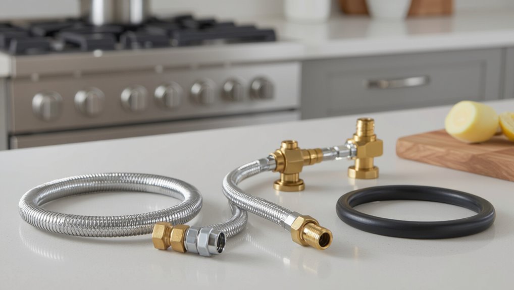
When preparing to disconnect a stove gas line, recognizing common connector types and fittings is essential for identifying shutoff points and selecting the correct tools.
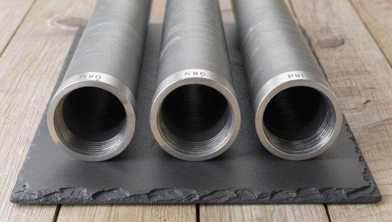
Typical connectors include flexible corrugated stainless steel tubing (CSST) with threaded adapters, rubber or braided appliance hoses with flare or compression ends, and rigid black iron piping with threaded fittings.
Visual inspection confirms material and connection style.
Recognizing threaded vs. flared vs. quick-disconnect fittings
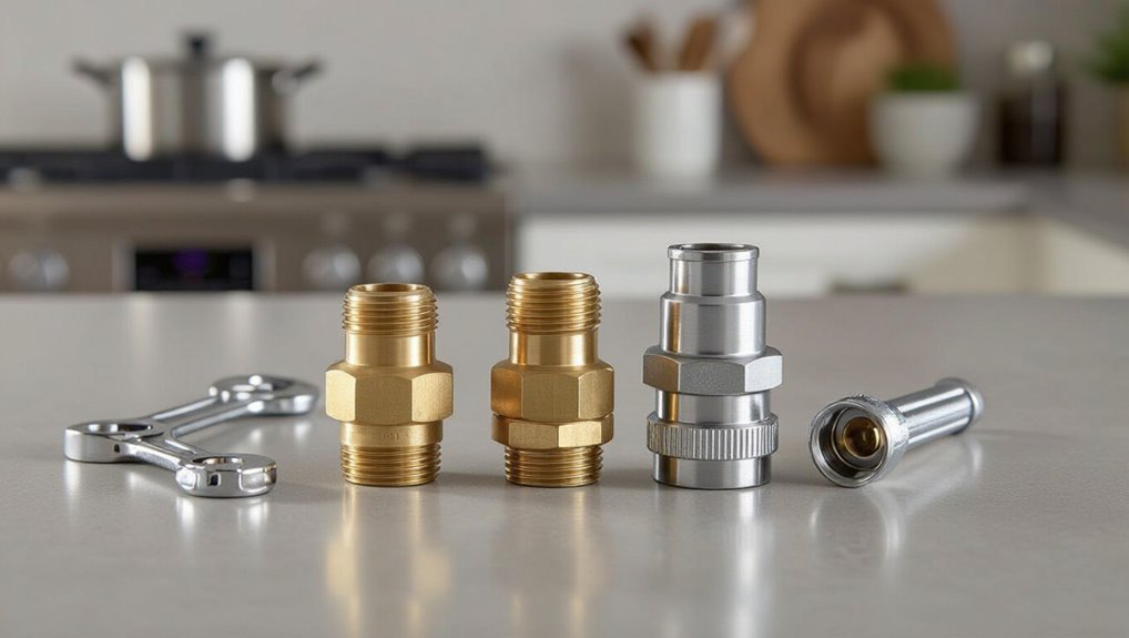
Several distinct fitting styles—threaded, flared, and quick-disconnect—are visually and functionally different, and recognizing them quickly helps guarantee the correct disconnection method is chosen.
Threaded fittings have visible male/female threads and require wrenches.
Flared fittings show a conical seating surface and use flare nuts.
Quick-disconnects feature push-fit collars or buttons for tool-free release; inspect for clips or locking rings before attempting disconnection.
Safety Checks and Leak Testing Methods
The section outlines practical methods for verifying a gas-tight connection after disconnecting the stove, beginning with a simple soap bubble test to reveal leaks at fittings.
It also covers the proper use and reading of a combustible gas detector to locate and quantify leaks.
Finally, it explains when a pressure test is warranted and the basic procedure for conducting one safely.
How to perform a soap bubble test
Begin by preparing a mild soap solution and applying it generously to all gas connections, fittings, and the valve area to reveal any leaks.
Observe for steady bubble formation indicating a leak. If bubbles appear, tighten fittings or shut the valve and call a professional. Confirm no bubbles before restoring service.
- Inspect visually
- Apply solution
- Watch for bubbles
- Record results
Using a combustible gas detector: procedure and interpretation
Use a handheld combustible gas detector to scan all connections, joints, and valve areas after the soap-bubble check to detect leaks that bubbles might miss. The operator moves slowly, pauses at fittings, notes alarm level, and ventilates if alarmed. Calibrate per manufacturer and retest after repairs.
| Location | Action | Response |
|---|---|---|
| Connector | Scan | Note ppm |
| Valve | Pause | Alarm? |
| Joint | Sweep | Mark |
| Pipe | Inspect | Recheck |
When and how to pressure test the line
Following the combustible gas scan and any repairs, pressure testing verifies system integrity under controlled conditions.
The technician isolates the segment, attaches a calibrated gauge, pressurizes with inert test gas or air to specified psi, and holds for the required dwell time.
Observe gauge and soap-test fittings. Any drop mandates repair and retest.
Record results and restore normal service only after a successful test.
When to Call a Professional
If any persistent smell of gas, damaged fittings, or uncertain shutoff operation is present, a licensed technician should be contacted immediately.
Homeowners must also follow local codes, obtain required permits, and schedule inspections before or after disconnection as dictated by jurisdiction.
When calling a gas company or technician, provide the address, clear description of the problem, recent work performed, and any safety measures already taken.
Signs of unsafe conditions that require a licensed technician
When unusual odors, visible damage, persistent leaks, or erratic burner behavior appear, a licensed technician should be contacted immediately; these signs indicate hazards beyond routine homeowner repairs and need professional diagnosis and repair.
Additional warning signs include dead carbon monoxide detectors, hissing sounds, scorch marks, repeated pilot failures, corroded fittings, or evidence of previous improper repairs—any of which warrant immediate professional assessment.
Local codes, permits, and inspections to consider
Because gas-line work affects public safety and property, many municipalities mandate specific permits, licensed technicians, and post-work inspections before a stove can be reconnected or a line altered.
Responsibilities and timelines vary; compliance prevents fines and hazards.
Consider:
- Permit requirements for disconnection or relocation.
- Licensed gas fitter or plumber mandates.
- Mandatory leak-testing and pressure inspections.
- Final municipal or utility sign-off before reuse.
How to communicate the issue to a gas company or technician
Why contact a professional rather than attempting a DIY fix? A technician offers certified leak detection, safe shutoff, and code-compliant disconnection.
When calling, provide appliance model, symptoms, smell of gas, recent work, and exact location. Report any pilot light issues, audible hissing, or evacuations already taken.
Request arrival window, license verification, cost estimate, and emergency response procedures.
Troubleshooting Common Problems
Common issues that arise during disconnection include stuck fittings or seized connectors, minor leaks after reconnection, and questions about whether a damaged supply line can be repaired or must be replaced.
Guidance covers safe removal methods for seized parts, steps to stop and fix small leaks, and criteria for repair versus replacement of compromised lines.
The goal is to enable safe, informed decisions while recognizing when professional service is required.
Stuck fittings or seized connectors and safe removal methods
Encountering a stuck fitting or seized connector is a frequent obstacle when disconnecting a stove gas line, often caused by corrosion, overtightening, or thread-lock compounds.
First, verify gas is off and area ventilated. Apply penetrating oil, allow dwell time, then use properly sized wrenches with steady, controlled force.
If immobile, stop and consult a licensed gas technician to avoid damage or leaks.
Minor leaks after reconnection and fixes
After freeing a seized fitting and reconnecting the gas line, a small leak can still appear at the joint or valve due to imperfect threads, damaged tape, or uneven tightening.
The technician should shut off gas, apply soapy water to locate bubbles, tighten fittings incrementally, replace plumber’s tape or use approved sealant, retest, and, if bubbling persists, consult a qualified gas professional immediately.
Damaged supply lines: repair vs. replacement decision
Assess the extent of visible damage and the risks it poses before deciding whether to repair or replace a stove supply line.
Small nicks or loose fittings may be repaired temporarily with approved connectors or tape, but corrosion, deep gouges, kinks, or aging flexible lines warrant full replacement.
Prioritize safety codes and professional inspection; replacement minimizes leak risk and guarantees compliance with local regulations.
Preventing Future Issues and Maintenance Tips
A regular inspection schedule for stove gas connections helps identify wear, corrosion, or loose fittings before they become hazards.
Emphasizing correct installation practices and use of approved fittings reduces the chance of future leaks.
Storing replacement parts and keeping installation records and manuals in a safe, accessible place simplifies maintenance and response if issues arise.
Routine inspection schedule for stove gas connections
Regularly inspecting stove gas connections prevents small issues from becoming dangerous problems.
A concise monthly-to-annual schedule balances safety and effort: visual checks monthly, sniff-test and soap-solution checks quarterly, professional inspection annually, and after any repair or move.
Document findings and dates. Promptly address detected leaks or corrosion; replace flexible lines per manufacturer timelines to maintain integrity and compliance.
- Visual monthly
- Soap test quarterly
- Annual professional
- After repairs/moves
Proper installation practices to avoid leaks
When installing a stove gas connection, following manufacturer specifications and local codes guarantees a secure, leak-free setup from the start.
Use approved fittings, correct thread sealant, and properly rated flexible connectors. Confirm joints are tightened to torque specs, avoid overbending lines, and position shutoff valves accessibly.
Test with a soap solution or electronic detector and document results for future reference.
Safely storing replacement parts and documentation
Once installation is verified leak-free, attention should shift to organizing and protecting replacement parts and documentation to simplify future maintenance and reduce downtime.
Store spare fittings, valves, and connectors in labeled, sealed containers away from moisture and heat.
Keep copies of manuals, photos of installations, and receipts in a fireproof folder or digital backup.
Periodically inventory and replace aged components.
Safety Mistakes to Avoid
The text highlights common safety mistakes that increase the risk of ignition or allow dangerous gas buildup.
It warns against incorrect tools or using improper sealants on gas fittings, which can compromise connections.
It also notes frequent DIY errors that lead to code violations and unsafe installations.
Actions that can cause ignition or gas buildup
Avoid actions that introduce sparks, open flames, or confined leaks while disconnecting a gas line; any ignition source or trapped gas increases the risk of an explosion or asphyxiation.
One must avoid operating electrical switches, using mobile phones, creating static, or running engines nearby.
Do not block ventilation or enclose the area; ventilate immediately and evacuate if a strong odor of gas persists.
Incorrect use of tools or sealants on gas fittings
Disconnecting a stove’s gas line requires correct tools and proper sealants; misuse can strip threads, fracture fittings, or create leaks that lead to dangerous gas release.
Using pliers instead of a proper wrench, overtightening, applying wrong thread tape, or using incompatible pipe dope damages connections.
Tools and sealants must match manufacturer and code specifications; improper choices compromise seals and increase risk.
DIY scenarios that commonly lead to code violations
Homeowners often attempt stove gas work without permits, proper fittings, or code knowledge, creating common DIY scenarios that produce violations and safety hazards.
Typical mistakes include improper pipe materials, omitted shutoff valves, unsecured flexible connectors, incorrect thread sealing, and neglected inspections.
These actions violate local codes, risk leaks, carbon monoxide, and insurance denial.
Professional permits and certified installers prevent such hazards.
Quick Reference Checklist
A concise checklist guides the sequence of actions before, during, and after disconnecting the gas line.
It covers pre-disconnect preparations, a step-by-step disconnect and leak test procedure, and post-disconnect restoration and verification.
The checklist is designed as a quick-reference tool to guarantee each critical task is completed safely and in order.
Pre-disconnect checklist
Checklist: before any work begins, verify that the main gas shutoff is accessible and functioning, confirm all appliance controls are off, ascertain ventilation is adequate, have a wrench sized for the gas fitting and a gas-rated cap or plug ready, keep a functioning carbon monoxide detector nearby, and arrange for a second person to be present or on call.
- Confirm utility shutoff and test accessibility.
- Ascertain clear ventilation paths.
- Gather tools and cap/plug rated for gas.
- Position a standby person and CO monitor.
Step-by-step disconnect and test checklist
Begin by shutting off the appliance valve, then the main gas supply, and confirm both remain closed.
Next, disconnect the flexible connector with the properly sized wrench while supporting the stove to prevent movement.
Verify no audible hissing.
Apply soapy water to fittings; watch for bubbles.
Use a handheld gas detector.
Cap or plug the open line.
- Confirm valves closed
- Support stove
- Soap test
- Detector check
Post-disconnect and restoration checklist
After the gas line is secured and capped, perform a concise post-disconnect and restoration checklist to confirm safety and readiness for future reconnection:
- Verify cap integrity and apply approved sealant; confirm no visible damage.
- Ascertain area ventilation and absence of odors; use gas detector if available.
- Label line status and document disconnection date and technician contact.
- Restore appliance access, keep valve closed until certified reconnection.
Conclusion
Careful, calm consideration completes the course: confidently cutting connection requires caution, clear checks, and correct tools. Following the step-by-step safety sequence secures success, since shutting the supply, sensing for scents, and sealing fittings stop spilled gas and serious setbacks. Regular routine readiness, respectful reminders, and recommended reinforcements reduce risks. Remember: rushed reactions ruin results—responsible removal remains the reliable route to prevent problems and preserve peace of mind.