How to Calibrate a Water Pressure Gauge: Step-by-Step Guide for Accurate Readings
To calibrate a water pressure gauge accurately, follow these steps: isolate and inspect the gauge, connect a certified reference standard and calibration pump, and apply known pressures across the gauge’s operating range. Log both the gauge and reference readings at each test point. Stabilize the readings, cycle pressures to check for hysteresis, and adjust the zero or span using the gauge’s adjustment screw or digital menu. Record any correction factors, certify your results, and adhere to safety protocols and frequency guidelines. For complete procedural details, refer to the full instructions.
What a Water Pressure Gauge Measures and Why Calibration Matters
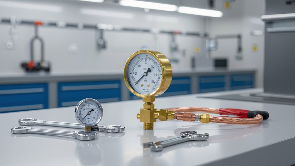
A water pressure gauge measures the force exerted by water in a system, typically using mechanical elements like Bourdon tubes, diaphragm sensors, or electronic transducers.
Accurate readings are critical because errors can compromise safety, reduce system performance, and lead to regulatory noncompliance.
Regular calibration—scheduled intervals and after events such as repairs, impacts, or suspect readings—ensures ongoing reliability.
How water pressure gauges work (mechanisms and common types)
Pressure gauges translate fluid force into a readable indication by converting pressure-induced movement into mechanical displacement or an electrical signal.
Common mechanisms include Bourdon tubes, diaphragms, and bellows for mechanical gauges, and strain gauges or piezoelectric sensors for electronic types.
Understanding these types aids in deciding calibration methods and tools when learning how to calibrate water pressure gauge for reliable measurements.
Risks of inaccurate readings (safety, system performance, compliance)
Understanding the operating principles of Bourdon tubes, diaphragms, bellows, and electronic sensors helps frame why incorrect readings occur and why they matter.
Inaccurate gauges can endanger personnel, cause overpressure failures or undetected leaks, degrade pump and valve performance, trigger unnecessary maintenance, and lead to regulatory noncompliance with fines or shutdowns.
Reliable calibration mitigates these safety, performance, and compliance risks.
When to calibrate a gauge (frequency and triggers)
When should a water pressure gauge be calibrated to guarantee accurate, reliable readings?
Calibration frequency depends on usage intensity, criticality, and environment: high-use or safety-critical systems require quarterly checks; moderate systems biannually; low-use annually.
Calibrate after installation, repairs, suspected drift, impact, exposure to harsh conditions, or failed inspections.
Maintain records and adjust intervals based on historical stability and regulatory requirements.
Tools and Materials Needed for Calibration
A concise inventory of required and optional equipment sets the stage for effective calibration.
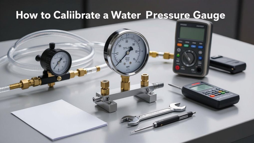
Essential items include a calibration pump, a certified reference gauge, adapters, a wrench, and appropriate sealant; optional tools such as a digital manometer, vacuum pump, or data logger improve precision and record keeping.
The choice of reference standard should match the gauge’s range and carry current certification to guarantee traceability.
Required tools (calibration pump, reference gauge, adapters, wrench, sealant)
Precision in calibration begins with assembling the correct tools: a calibrated reference gauge, a hand or electric pressure calibration pump, a set of adapters and fittings to match the gauge ports, an adjustable wrench for secure connections, and a compatible thread sealant to prevent leaks.
Each item should match system pressure range and thread type; inspect for damage, clean contact surfaces, and keep spare adapters for quick swaps.
Optional tools for precision (digital manometer, vacuum pump, data logger)
Include a few optional instruments to enhance accuracy and diagnostics: a digital manometer for higher-resolution pressure readings, a vacuum pump to test gauge response below ambient and check for leaks, and a data logger to record long-term trends and transient events.
These tools assist verification, capture transient behavior, and isolate faults. Select robust, calibrated units compatible with water systems and pressure ranges used during calibration.
Choosing an appropriate reference standard and certifications
When selecting a reference standard for calibrating a water pressure gauge, one should prioritize instruments with traceable certification to national or international standards and an accuracy at least one order of magnitude better than the gauge under test.
Choose standards with recent calibration certificates, defined uncertainty budgets, and compatible pressure ranges.
Prefer recognized labs (ISO/IEC 17025) and documented chain of custody for reliable, defensible results.
Preparing the Gauge and System for Calibration
Before calibration, the gauge must be safely isolated from the plumbing system to prevent pressure changes or fluid loss.
A brief inspection should confirm there are no visible damages, leaks, or a notable zero offset.
Finally, the face and connections should be cleaned, any trapped air vented, and the gauge mounted securely and level for accurate readings.
Isolating the gauge from the plumbing system safely
Shut off the inlet valve and relieve any trapped pressure to isolate the gauge from the plumbing system; this prevents fluid flow and reduces the risk of sudden spikes during calibration.
Then close isolation valves and use a bleed or drain port to verify zero pressure.
Tag valves as out-of-service, secure fittings with appropriate caps or blanks, and wear PPE while performing isolation steps.
Inspecting the gauge for damage, leaks, and zero offset
Inspect the gauge and its connections for physical damage, fluid leaks, and a correct zero reading prior to applying test pressures.
The inspector verifies glass/crystal integrity, pointer alignment, and housing condition.
Threaded joints and diaphragms are checked for seepage.
Any visible deformation, corrosion, or persistent zero offset is documented.
Faulty gauges are removed or tagged for repair before calibration proceeds.
Cleaning, venting, and mounting considerations
Having verified physical integrity and documented any zero offset, attention turns to preparing both gauge and system through cleaning, venting, and proper mounting to guarantee reliable calibration.
Remove debris and scale from ports, flush lines, and dry internal cavities.
Vent trapped air slowly to prevent false readings.
Securely mount the gauge vertically with appropriate fittings and torque, avoiding vibration and strain on connections.
Step-by-Step Calibration Procedure
The procedure begins with establishing a safe workspace and confirming the gauge reads zero before pressurization.
Next, a calibrated reference gauge and pressure source are connected. Pressure is applied in increments while readings are recorded, and any mechanical or digital adjustments are made as needed.
Finally, the instrument is verified at multiple points across its range to confirm accuracy.
Establishing a safe working environment and baseline zero check
Before any adjustments are made, personnel must confirm that the work area is secure and that the gauge, associated fittings, and test equipment are isolated from live pressure sources.
Inspect equipment for damage, verify depressurization, and guarantee adequate lighting and slip-free footing.
Record ambient temperature.
Verify venting paths and tag out connected valves.
Perform a zero reading with the gauge at atmospheric pressure.
Connecting the reference gauge and calibration equipment
With the work area secured and the gauge depressurized, attention shifts to assembling the reference gauge and calibration apparatus.
The technician verifies compatibility, selects suitable fittings, and installs isolation valves. A calibrated deadweight tester or master gauge mounts to the test manifold; all connections receive proper seals and torque.
Leak checks follow at ambient pressure before proceeding to controlled pressurization.
Applying pressure increments and recording readings
Begin pressurizing the system in controlled increments, pausing at each setpoint to record the reading from both the test gauge and the reference instrument.
At each increment, note steady-state values and any hysteresis during pressure release.
- Record setpoint, test reading, reference reading
- Wait for stabilization (specified time)
- Repeat upward and downward cycles
- Log environmental conditions
Adjusting the gauge (mechanical and digital adjustment methods)
Adjust the gauge using the method appropriate to its design—mechanical gauges require careful mechanical manipulation of the pointer mechanism, while digital models rely on menu-driven span and zero adjustments or software configuration.
For mechanical types, turn the zero/set screw gently and recheck.
For digital units, enter calibration mode, apply known reference pressure, adjust span/offset, save settings, and exit.
Verifying calibration at multiple points across the range
Several checkpoints across the gauge’s operating range should be tested to confirm linearity and accuracy. The technician applies known pressures at low, mid, and high points, comparing readings to a calibrated reference.
Record deviations, calculate error percentages, and determine if adjustments are effective. Repeat measurements ascending and descending to detect hysteresis.
Document results and decide whether further adjustment or replacement is necessary.
Final zero-check and reinstallation
After confirming accuracy across low, mid, and high checkpoints and noting any hysteresis, the technician performs a final zero-check to guarantee the gauge returns to true zero with no applied pressure.
Once zero is stable, the gauge is isolated, fittings are torqued to specification, seals inspected, and the unit is reinstalled.
A brief functional test confirms correct operation before returning equipment to service.
Interpreting Calibration Results and Tolerances
The calibration results are evaluated against application-specific tolerances, with residential systems typically allowing wider error margins than industrial installations.
Any measured deviation should be converted into a correction factor, recorded in the calibration report, and applied to future readings or labeling.
A gauge that cannot be corrected within the allowable tolerance or shows signs of mechanical failure should be scheduled for repair or replacement.
Determining acceptable error margins for residential vs. industrial use
Acceptable error margins differ markedly between residential and industrial water pressure applications because risk, performance requirements, and regulatory standards vary; residential systems typically tolerate wider deviations (often ±5–10%) without functional impact, whereas industrial systems frequently demand tighter tolerances (commonly ±1–2% or better) to protect equipment, processes, and safety.
Decision factors include system criticality, liability exposure, manufacturer specifications, and applicable codes.
Calculating correction factors and documenting adjustments
With acceptable error margins established for the application, attention shifts to quantifying how an individual gauge deviates from the reference and expressing that deviation as a correction factor.
Calculate correction factor = reference reading ÷ gauge reading at multiple points, average or interpolate as required.
Record test conditions, correction values, uncertainty, date, technician, and follow-up actions in a calibration certificate for traceability.
When to repair or replace a gauge
Decide whether a gauge should be repaired or replaced by comparing its measured deviations and associated uncertainty against the application’s tolerance limits and the organization’s risk criteria.
If deviations plus uncertainty exceed tolerances or show non-linear error, replace.
If errors are systematic, within repairable range, and cost-effective, repair and recalibrate.
Document decisions, traceability, and any interim use restrictions to maintain safety and compliance.
Common Calibration Challenges and How to Overcome Them
Common calibration challenges include fluctuating pressure and unstable readings, as well as mechanical issues like leaks, stuck needles, and hysteresis that can distort measurements.
Technicians should systematically identify and isolate the source of instability, repair or replace faulty components, and use damping or averaging where appropriate.
Environmental factors such as temperature and altitude must be accounted for with corrections or controlled conditions to prevent biased results.
Dealing with fluctuating pressure and unstable readings
Many technicians encounter fluctuating pressure and unstable readings during calibration, which often stem from transient flow conditions, air in the line, or mechanical vibration. Diagnosing the root cause quickly is essential to obtaining a reliable zero and span.
The procedure involves stabilizing flow, bleeding trapped air, isolating vibration sources, using a dampener or snubber, and waiting for readings to settle before recording calibration points.
Addressing leaks, stuck needles, and hysteresis
Inspecting for leaks, freeing sticky needles, and quantifying hysteresis are frequent steps when calibration yields inconsistent or non-repeatable gauge readings.
Technicians isolate the gauge, apply controlled pressures, and observe needle response. Leaks are sealed or fittings replaced; sticky pointers receive gentle mechanical or solvent cleaning.
Hysteresis is measured by cycling pressures and applying correction factors or replacing worn diaphragms to restore accuracy.
Ensuring temperature and altitude do not bias results
Although often overlooked, ambient temperature and elevation greatly affect pressure gauge readings and must be controlled or compensated during calibration.
The technician records temperature and barometric pressure, applies manufacturer temperature compensation curves, or performs calibration in a controlled environment.
For high-altitude sites, adjust reference standards for reduced air pressure.
Document conditions and corrections to guarantee traceable, reproducible results and prevent systematic bias.
Maintenance, Record-Keeping, and Compliance
A consistent calibration schedule and concise logbook entries guarantee gauges remain accurate and provide an audit trail for maintenance actions.
Calibrated instruments should be clearly labeled with dates, next due checks, and unique identifiers to support traceability.
Compliance requires awareness of applicable regulatory standards and certification bodies to which records and procedures must conform.
Creating a calibration schedule and logbook entries
Establishing a consistent calibration schedule and maintaining detailed logbook entries guarantee water pressure gauges remain accurate and traceable over time.
A clear schedule sets intervals, triggers, and responsible personnel. Logbooks record dates, standards used, results, and actions taken.
- Calibration interval and justification
- Technician name and signature
- Reference standard and uncertainty
- Corrective actions and disposition
Labeling calibrated equipment and traceability best practices
When calibration is complete, each water pressure gauge should receive a durable, legible label that documents the calibration date, next due date, calibration technician or lab identifier, and a unique asset or tag number.
This single label provides immediate status visibility while linking the instrument to its detailed logbook entry and traceability records.
Electronic records should mirror labels, include measurement uncertainties, reference standards, and retain audit trails for change control.
Regulatory standards and certification bodies to consider
The label and electronic records that document calibration status and traceability also serve as the primary evidence for compliance with applicable regulatory standards and certification schemes. Organizations should reference ISO/IEC 17025, local water authority rules, and industry-specific standards; accreditation bodies (e.g., A2LA, UKAS) validate competence. Maintain documented procedures, periodic audits, and retained certificates to demonstrate ongoing compliance.
| Standard | Body |
|---|---|
| Calibration quality | ISO/IEC 17025 |
| Accreditation | A2LA/UKAS |
Tips to Improve Long-Term Accuracy
Long-term accuracy is supported by correct storage and careful handling to prevent mechanical shock and corrosion.
Proper installation—secure mounting, correct orientation, and appropriate fittings—reduces systematic error at the source.
Selection between digital and analog instruments should be based on required resolution, environmental robustness, and maintenance capabilities.
Proper storage and handling of gauges
Proper storage and careful handling greatly extend a gauge’s accuracy by preventing mechanical shock, contamination, and corrosion that can alter readings.
Store gauges in padded, climate-controlled cases, away from vibration and direct sunlight. Cap and clean connections before storage.
Handle instruments by the body, not the stem or dial.
Schedule periodic inspections and document condition to detect deterioration early.
Best practices for installation to minimize error
Install gauges with attention to alignment, support, and isolation to prevent mechanical strain, vibration, and thermal stress that can skew readings.
Mount on stable surfaces, use proper fittings and thread sealant, avoid direct sun and heat sources, and provide accessibility for maintenance.
Include dampeners or snubbers where pulsation occurs, and guarantee piping is free of trapped air and debris to preserve long-term accuracy.
When to use digital vs. analog gauges
Choose between digital and analog pressure gauges based on the application’s accuracy needs, environment, and maintenance capacity.
Digital gauges suit high-precision, data-logging, or remote monitoring; they require stable power and periodic calibration.
Analog gauges are robust, simple, and tolerate vibration or surge conditions with less frequent servicing.
Select type by required resolution, environmental hazards, budget, and available calibration resources to maintain long-term accuracy.
Quick Troubleshooting Flowchart for Calibration Failures
Begin by consulting the flowchart to quickly identify whether the gauge is reading zero, fluctuating, or displaying a constant offset. Each branch directs the user to targeted checks (connections, zeroing procedure, or reference device comparison) that eliminate common causes in order of likelihood.
Follow prescribed steps: verify fittings, repeat zeroing, substitute a calibrated reference, inspect for leaks or blockage, and document results for follow-up.
Conclusion
Calibration completes the cycle: verifying readings, restoring trust, and ensuring safety. It confirms that gauges measure true pressure, aligns instrument output with standards, and reduces costly surprises. It prevents drift, documents compliance, and extends service life. It saves time, protects systems, and upholds performance. Regular checks, clear records, and prompt adjustments sustain accuracy, support inspections, and reassure operators—turning a simple test into reliable protection, consistent performance, and measurable peace of mind.