How Does a Check Valve Work? Simple Explanation, Types, and Applications
A check valve allows fluid to flow in one direction while automatically preventing backflow. It features a movable closure—like a disc, ball, diaphragm, or spring-loaded poppet—that opens when upstream pressure is higher than downstream pressure and seals when the pressure reverses. Common types include swing, lift, ball, diaphragm, and spring checks, as well as wafer, flanged, and foot valves for specific applications. Choosing the right material and size is essential to match the system’s pressure and fluid type. For further guidance on selection, installation, and maintenance, continue reading.
What a Check Valve Does and Why It Matters
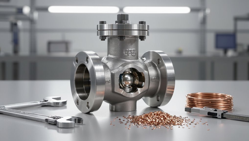
A check valve is a one-way valve that permits flow in a single direction and closes automatically to prevent backflow.
It is commonly used to protect pumps, maintain system pressure, and prevent cross-contamination in piping and fluid systems.
When a check valve fails or is absent, issues can include pump damage, reverse flow contamination, and system flooding or loss of prime.
Clear definition of a check valve and primary function
Check valves are simple mechanical devices that allow fluid to flow in one direction and automatically prevent reverse flow. They act without external control by relying on pressure differentials and internal moving parts (disc, ball, or flap) to open and close.
A check valve is defined as a passive, single-direction device whose primary function is to protect systems from backflow, ensuring flow integrity and pressure stability—how does check valve work.
Common reasons check valves are used in systems
Because preventing reverse flow preserves system integrity, check valves are installed to protect equipment, maintain pressure, and prevent contamination by permitting flow only in the designated direction.
They also prevent backflow-induced water hammer, isolate malfunctioning components, maintain prime in pumps, enable cascade operation in multi-stage systems, and guarantee unidirectional chemical dosing and sanitary separation in process and utility networks.
Quick scenarios showing consequences of failed or missing check valves
Having outlined why check valves are installed, it is useful to look at concrete failures and omissions to see the operational, safety, and financial consequences.
Backflow floods buildings, contaminates potable water, and damages pumps.
Reverse flow in chemical lines creates hazardous reactions.
Steam systems suffer water hammer and ruptures.
Process interruptions cause production losses and costly downtime for repairs and regulatory fines.
How a Check Valve Works: Simple Mechanical Explanation
A check valve contains a few basic internal parts—body, seat, and a movable closure element such as a disc, ball, or piston—arranged to create a defined flow path.
When upstream pressure exceeds downstream pressure, the closure element is pushed off its seat to open the passage; when pressure reverses or drops, the element returns to the seat to stop flow.
Directional flow is enforced by the geometry of the seat and closure and by sealing surfaces or elastomeric inserts that guarantee a tight shut-off.
Basic internal components and flow path
At the heart of every check valve are a few simple parts—body, inlet and outlet ports, a movable sealing element (such as a disc, ball, or poppet), and a seat—arranged to permit flow in one direction and block it in the other.
Internal guides, springs or retainers (when present) keep the element aligned. The flow path channels fluid toward the seat; reverse flow encounters the sealing surface, preventing passage.
Opening and closing mechanics under pressure differences
When upstream pressure exceeds the downstream pressure by enough to overcome any spring force or seating friction, the movable element lifts from its seat and creates a flow path.
If the pressure differential reverses or falls below that threshold, the element returns to the seat—either by spring action, gravity, or fluid forces—forming a tight seal and stopping reverse flow.
Valve response depends on differential magnitude, flow inertia, and damping.
Flow direction and sealing mechanisms
Many check valves permit flow in only one direction by combining a movable closure element—such as a disc, ball, or flap—with a precisely machined seat so that pressurized fluid pushes the element away from the seat to open the passage.
In contrast, reverse flow forces the element back against the seat to form a seal.
Additional features—springs, hinges, or elastomeric cushions—control response, minimize leakage, and dampen slam.
Main Types of Check Valves and How Each Operates
The section outlines the principal check valve designs and how each type behaves in service.
It will cover swing, lift, ball, diaphragm, and spring (including spring‑loaded poppet) check valves, noting operation, strengths, and weaknesses.
- Practical and reliable
- Vulnerable in specific conditions
- Engineered for particular needs
Swing check valve operation, advantages, limitations
Swing check valves rely on a hinged disc that swings open to allow forward flow and closes under reverse pressure to prevent backflow. They operate simply with low pressure drop and suitability for large-diameter piping.
Advantages include reliability, minimal maintenance, and cost-effectiveness.
Limitations involve potential water hammer, sensitivity to installation orientation, slower response than poppet types, and unsuitability for high-viscosity fluids.
Lift check valve operation, advantages, limitations
Lift check valves permit flow by raising a guided disc or poppet off its seat in response to upstream pressure and reseat when downstream pressure or gravity forces reverse flow.
They offer rapid closure, minimal backflow, and suitability for high-pressure, straight-line installations.
Limitations include sensitivity to debris, potential for seat wear, and reduced effectiveness in low-flow or turbulent conditions requiring precise alignment and maintenance.
Ball check valve operation, advantages, limitations
Following the discussion of lift check valves, attention shifts to ball check valves, which use a free-moving spherical element that seats against a conical or tapered seat to block reverse flow.
Operation relies on forward pressure displacing the ball, allowing flow, and gravity or backpressure returning it to seal.
Advantages include simplicity, low cost, and compactness; limitations are susceptibility to wear, potential leakage with particulates, and limited high-pressure suitability.
Diaphragm check valve operation, advantages, limitations
A diaphragm check valve uses a flexible membrane that deflects to permit forward flow and presses against a seating surface to prevent backflow, combining simple mechanics with a tight seal for contaminant-sensitive systems.
Operation is pressure-driven: forward differential opens the diaphragm; reverse pressure collapses it onto the seat.
Advantages include low leakage, suitability for viscous or particulate fluids, and minimal maintenance; limitations are limited pressure/temperature ratings and slower response.
Spring check valve (including spring-loaded poppet) operation, advantages, limitations
Spring check valves rely on a spring-loaded element—commonly a poppet—that is held against a seat until forward pressure compresses the spring and opens the flow path.
When upstream pressure falls or reverse flow begins, the spring forces the poppet back onto the seat to stop backflow.
They provide compact, fast response, suitable for pulsating systems; limitations include higher cracking pressures, potential wear from frequent cycling, and sensitivity to debris.
Wafer and dual-flanged check valves operation and installation differences
Building on the compact, fast-acting nature of spring-loaded poppet designs, wafer and dual-flanged check valves offer alternative installation and flow-control approaches for larger piping systems.
Wafer valves fit between flanges, saving space and weight but need flange alignment and backing.
Dual-flanged valves bolt between pipe flanges, provide stronger sealing and easier maintenance, and suit higher-pressure or more rigid piping networks.
Specialty check valves (non-return valve, foot valve, vacuum breaker) brief uses
Specialty check valves address niche flow-control needs where standard designs fall short: non-return valves prevent backflow in process lines, foot valves protect pumps and retain prime at suction intakes, and vacuum breakers stop pipe collapse or siphoning by admitting air when internal pressure falls.
Each type suits specific contexts—chemical plants, irrigation and booster systems, and plumbing or HVAC installations—minimizing damage and maintaining reliable operation.
Materials, Sizes, and Pressure Ratings Selection Basics
Selection of a check valve begins with matching material to service—metals for high pressure and temperature, plastics for corrosion resistance in lower-pressure systems, and elastomers for sealing where flexibility is required.
Size and Cv determine flow capacity and pressure drop, while pressure class must meet system maximums.
Temperature and chemical compatibility further constrain material and elastomer choices to guarantee long-term performance.
Common materials and suitability (metal, plastic, elastomers)
Material choice for check valves directly determines compatibility with fluid chemistry, temperature range, mechanical wear, and pressure capacity.
Metals (stainless steel, bronze, carbon steel) suit high temperatures, pressures, and abrasive or corrosive services with good strength.
Plastics (PVC, CPVC, PVDF) offer corrosion resistance, lightweight and lower cost for moderate pressure and temperature.
Elastomers (EPDM, Viton, NBR) provide seals and flexibility but limit temperature and chemical ranges.
Size, flow coefficient (Cv), and pressure class considerations
Sizing and pressure-class decisions hinge on three interdependent parameters: the valve size, its flow coefficient (Cv), and the pressure rating appropriate for the system.
Proper sizing prevents excessive head loss and guarantees required flow. Cv quantifies flow capacity at a given differential.
Pressure class selection matches maximum operating and surge pressures, safety margins, and applicable standards to avoid leakage or mechanical failure.
Temperature and chemical compatibility factors
Temperature and chemical compatibility are critical determinants when choosing check valve materials, because they directly affect durability, sealing integrity, and safe operation across the designated service conditions.
Selection requires matching body, seat, and seal materials to fluid composition and temperature ranges, accounting for corrosion, swelling, embrittlement, and thermal expansion.
Verify ratings with manufacturer data and industry standards to guarantee reliable long‑term performance.
Installation, Orientation, and Best Practices
Correct orientation and strategic pipeline placement are essential for check valves to function reliably and prevent reverse flow.
Installers should allow clearances for access and maintenance, follow pre-installation checks, and perform commissioning steps to verify operation.
Piping layout should minimize abrupt changes and include features to reduce water hammer and backflow.
Correct orientation and pipeline placement
When installing a check valve, proper orientation and placement within the pipeline are critical to ensuring reliable one-way flow and preventing damage. The valve must be aligned so the flow direction arrow matches system flow and the seat remains accessible for inspection and maintenance.
Placement should minimize turbulence and avoid high-vibration zones, upstream pressure spikes, or pockets that trap fluid. Install in recommended orientation for valve type.
Installation clearances and access for maintenance
Adequate installation clearances and unobstructed access are essential for routine inspection, servicing, and safe removal of a check valve. Planners should allow space for flange or union disassembly, actuator removal if present, and access to the seat and hinge areas without disturbing adjacent equipment.
Sufficient room for tools, lifting gear, and inspection ports reduces downtime. Clear labeling and removable supports aid safe, efficient maintenance.
Piping layout tips to avoid water hammer and reverse flow
Because rapid velocity changes and pressure surges are the primary causes of water hammer and reverse flow, piping layouts should minimize sudden directional changes, short-circuiting loops, and long unsupported spans that permit column separation.
Install gradual bends, adequate pipe supports, and straight runs upstream of check valves.
Include air/vacuum relief, appropriate valve sizing, and flow conditioning to reduce transient forces and guarantee reliable check valve operation.
Pre-installation checks and commissioning steps
1. The technician verifies valve type, pressure rating, orientation, and cleanliness before installation.
Torque, gasket compatibility, and flow direction are confirmed.
Commissioning includes leak testing, gradual pressurization, and functional check under normal flow.
- Confidence in correct operation
- Relief from potential failure
- Assurance of system longevity
Performance Issues, Common Failures, and Troubleshooting
Common performance issues in check valves include leakage, sticking, vibration, and noise, each indicating different underlying causes.
Troubleshooting focuses on diagnosing reverse flow or poor sealing by inspecting for debris, wear, or spring fatigue and testing valve movement under operating conditions.
Decisions to repair or replace hinge on the extent of damage, availability of spare parts, and cost-effectiveness of restoring reliable operation.
Typical failure modes (leakage, sticking, vibration, noise)
Several recurrent failure modes affect check valves, most importantly leakage, sticking, vibration, and noise, each degrading performance and potentially causing system damage.
Leakage arises from wear, seat damage, or debris.
Sticking results from corrosion, deposits, or inadequate flow to reseat.
Vibration and chattering stem from fluid dynamics, loose components, or rapid cycling, accelerating wear and producing audible noise.
Diagnosing reverse flow or poor sealing
Leakage, sticking, vibration, and noise often presage more specific sealing problems such as reverse flow or inadequate closure; diagnosing these issues requires focused inspection and measurement rather than general observation.
Technicians verify flow direction with tracers or flow meters, measure upstream/downstream pressures for differential leakage, perform seat-leak tests at operating pressures, and assess closure timing.
Documented test data guides corrective action and confidence in repairs.
How to check for debris, wear, and spring fatigue
To evaluate debris, wear, and spring fatigue in a check valve, technicians inspect internal surfaces and moving parts for scoring, erosion, or foreign material. They measure clearances and seat contact with calipers or feeler gauges, and test spring characteristics using free-length and load checks against original specifications.
They also perform flow and pressure tests to detect leakage, document findings, and recommend corrective actions if tolerances are exceeded.
When to repair vs. replace
After inspection identifies debris, wear, or spring fatigue, the decision to repair or replace a check valve hinges on the extent of damage, operating requirements, and safety margins.
Minor debris removal, seat resurfacing, or spring replacement may suffice for low-risk systems.
Severe erosion, cracking, distorted internals, or critical-service applications warrant full replacement to restore reliability, certification, and acceptable downtime risk.
Maintenance, Inspection, and Testing Procedures
A concise maintenance program for check valves includes a routine inspection checklist with defined intervals and quick field tests to verify sealing and operation.
Technicians should follow clear procedures for cleaning, seat replacement, and reassembly to restore proper function.
Final pressure testing against acceptance criteria confirms integrity before returning the valve to service.
Routine inspection checklist and intervals
Routine inspections use a standardized checklist to verify valve integrity, seating, actuator function, and external condition at defined intervals.
Inspections document wear, corrosion, leakage indicators, and mounting security. Intervals depend on service severity: monthly for critical systems, quarterly for moderate, annually for low-risk.
Records guide replacement or overhaul decisions.
- Relief at proactive care
- Confidence in reliable operation
- Alarm prompting timely action
Simple field tests for leak and operation verification
Following scheduled inspections, simple field tests provide quick verification of a check valve’s leak tightness and functional response without requiring removal from service.
Operators can apply slight upstream pressure and monitor downstream for pressure decay, tap the valve to detect chatter or sticking, observe seat movement on transparent gauges or sight glasses, and confirm reverse-flow prevention with controlled backpressure checks while recording results for trend analysis.
Cleaning, seat replacement, and reassembly tips
Disassemble the check valve only after isolating the line and relieving all pressure.
Inspect components for wear, corrosion, and debris.
Clean parts with compatible solvents; avoid abrasives on sealing surfaces.
Replace damaged seats and seals with manufacturer-specified materials.
Lubricate moving parts lightly if recommended.
Reassemble in correct orientation, torque fasteners to spec, and verify seating surfaces align before returning to service.
Pressure testing and acceptance criteria
After cleaning, replacing seats and seals, and reassembling, the check valve must undergo pressure testing to confirm integrity and proper operation before being returned to service.
Testing follows specified hydrostatic or pneumatic procedures at designated test pressures for set durations.
Acceptance criteria include no leakage, correct cracking and seating behavior, stable pressure hold, and verification against manufacturer or code limits; document results and corrective actions.
Applications and Industry Examples
Applications of check valves span many sectors where preventing backflow and protecting equipment are critical. Examples include water and wastewater systems, HVAC/chilled and hot water loops, pump discharge and suction protection, steam/compressed air/gas networks, and chemical/process plants—each presenting distinct operational stakes and consequences.
Emotion-evoking considerations:
- reassurance of system integrity
- urgency of preventing contamination or equipment damage
- confidence in operational safety
Water and wastewater systems
In water and wastewater systems, check valves prevent backflow that could contaminate supply lines, damage pumps, or disrupt treatment processes by allowing fluid to flow in only one direction.
They protect pump stations, lift systems, and filtration units from reverse flow during shutdowns or power loss.
Selection prioritizes corrosion resistance, debris tolerance, low maintenance, and reliable sealing to meet regulatory and operational demands.
HVAC and chilled/hot water systems
Many HVAC and chilled/hot water systems rely on check valves to prevent reverse flow that can compromise temperature control, energy efficiency, and equipment longevity.
These valves guarantee proper zoning, maintain pump and heat exchanger operation, and reduce short-circuiting between supply and return lines.
Selection focuses on low cracking pressure, compatibility with glycol mixtures, and reliable sealing to minimize maintenance and system imbalance.
Pump discharge and suction protection
Pump discharge and suction protection relies on check valves to safeguard pumps from damaging backflow, water hammer, and reverse rotation by ensuring unidirectional flow at both the inlet and outlet.
Properly sized swing, lift, or piston check valves prevent reverse flow during shutdown, reduce transient forces, maintain prime, and minimize maintenance.
Strategic placement and routine inspection extend pump life and system reliability.
Steam, compressed air, and gas systems
Across steam, compressed air, and gas systems, check valves provide essential one-way flow control to prevent backflow, protect compressors and turbines, and limit pressure transients that can damage equipment.
They enable safe venting, isolate malfunctioning sections, and reduce surge and water hammer risks.
Selection prioritizes pressure rating, response speed, material compatibility, and minimal leakage to maintain system efficiency and safety.
Chemical and process industry examples
In chemical and process plants, check valves are deployed to guarantee unidirectional flow in feed lines, reactor inlets, and separation units, preventing backflow that could contaminate batches or upset downstream processing.
They protect pumps and compressors, isolate catalysts, and prevent cross-contamination between process streams.
Materials and designs resist corrosion, erosion, and fugitive emissions, meeting safety and regulatory requirements for high-temperature, high-pressure, and toxic services.
Choosing the Right Check Valve: Comparison and Decision Guide
Selection of a check valve hinges on a few clear decision factors—flow rate, pressure, media compatibility, cost, and maintenance burden—each weighted differently by application. The following quick recommendation matrix maps common scenarios to valve types to aid comparison and decision-making. Use the table as a starting point and adjust choices for specific system constraints.
| Scenario | Recommended Valve Type | Key Reason |
|---|---|---|
| High flow, low backpressure | Swing/check | Low head loss, handles large flow |
| Corrosive media | Ball/check with compatible materials | Material compatibility reduces failures |
| Space-limited or pulsating flow | Spring/check | Compact, responsive to flow changes |
Decision factors summarized (flow, pressure, media, cost, maintenance)
Ideal check valve selection hinges on five core factors: flow characteristics, system pressure, conveyed media, cost constraints, and maintenance requirements.
Evaluate flow rate and directionality, pressure range and transient events, chemical compatibility and particulate presence, upfront and lifecycle costs, and accessibility for inspection or repair.
Balance performance, longevity, safety, and budget to determine the most suitable valve type and materials for the application.
Quick recommendation matrix for common scenarios
Although each system has unique demands, a concise recommendation matrix helps engineers and technicians match common check valve types to typical scenarios by comparing performance, pressure limits, media compatibility, cost, and maintenance needs.
The matrix pairs swing, lift, ball, piston, and diaphragm valves with use cases: low-pressure general service, high-pressure steam, particulate-laden fluids, pulsating flows, and sanitary/chemical systems, noting pros, cons, and inspection intervals.
Safety, Regulations, and Standards to Consider
The discussion shifts to applicable industry standards and required certifications that govern check valve selection and installation.
It also highlights common safety risks—such as water hammer and backflow—and practical mitigation measures.
Finally, it stresses the importance of clear documentation and labeling to guarantee regulatory compliance and safe operation.
Relevant industry standards and certifications
Compliance with industry standards and certifications guarantees check valves meet safety, performance, and compatibility requirements across applications.
Manufacturers reference standards such as API 594, ASME B16.34, ISO 5208, and MSS SP-80 for design and pressure ratings; materials and testing follow ASTM specifications.
Certifications from PED/CE, UL, and ABS validate compliance for regional markets and critical installations, aiding procurement and regulatory approval.
Safety risks and mitigation (water hammer, backflow prevention)
Many installations face two primary hazards related to check valves: water hammer and unintended backflow.
Water hammer can cause pressure spikes and mechanical failure; mitigation includes slow-closing valves, surge tanks, air chambers, and proper piping support.
Backflow risks contaminate supply; prevention uses double-check assemblies, reduced-pressure zones, vacuum breakers, and routine testing.
Regular inspection and correct sizing reduce both hazards.
Documentation and labeling best practices
After addressing operational hazards like water hammer and backflow, attention shifts to documentation and labeling as tools for ongoing safety and regulatory adherence.
Documentation should record installation dates, model/serial numbers, maintenance logs, inspection intervals, and corrective actions.
Labels must indicate flow direction, pressure limits, valve type, and hazard warnings.
Compliance with local codes, ISO/PED/ASME standards, and traceability requirements is essential.
Cost Considerations and Lifecycle Economics
Cost assessments for check valves should weigh initial purchase price against expected maintenance costs and potential downtime.
Lifecycle analyses that include repair frequency, spare parts, and operational interruptions clarify long-term value.
Typical installations often show higher total cost of ownership for cheaper valves once maintenance and downtime are accounted for.
Purchase cost vs. long-term maintenance and downtime
When selecting a check valve, initial purchase price is only one element of total lifecycle expense; maintenance frequency, parts availability, and the production losses tied to downtime often determine the real long-term cost.
Higher-quality valves may cost more upfront but reduce inspection intervals, spare parts needs, and unscheduled shutdowns.
Decision-makers should weigh reliability, serviceability, and warranty against capital outlay to minimize total operating expense.
Total cost examples for typical installations
Having contrasted upfront price with ongoing maintenance and downtime, practical examples illustrate how lifecycle costs accumulate in real installations.
A municipal water pump station replaces a $400 flapper valve annually versus a $1,200 spring check lasting five years; cumulative five‑year costs: $2,000 versus $1,200.
An industrial steam line shows higher repair and shutdown penalties, shifting preference to robust, higher‑initial‑cost designs.
Practical Tips and Common Mistakes to Avoid
Common installation errors that prematurely wear check valves, such as misalignment, improper orientation, and inadequate support, are summarized to prevent early failure.
Recommended operational practices to maintain reliability — including flow-rate control, periodic inspection, and correct flushing procedures — are outlined.
A concise pre-commissioning checklist for technicians is provided to guarantee proper installation and initial testing.
Top installation mistakes that shorten valve life
Why do so many check valves fail prematurely?
Incorrect orientation, improper alignment, and inadequate support cause stress and leakage.
Using wrong materials for fluid or temperature, insufficient flushing to remove debris, and over-tightened fasteners damage internals.
Skipping required strainers or using oversized piping creates turbulence and water hammer.
Neglecting manufacturer torque and preload specifications shortens service life drastically.
Operational tips to maximize reliability
Regular, disciplined operating practices greatly extend check valve life and reduce unplanned outages.
Operators should minimize rapid cycling, avoid slam conditions by controlling flow rates, and prevent reverse flow surges.
Maintain proper system pressures, monitor vibration and leakage trends, and schedule inspections based on service severity.
Replace worn seals and springs promptly.
Document anomalies and adjust operating procedures to prevent recurring stressors.
Checklist to hand to technicians before commissioning
Before commissioning, technicians should be given a concise, prioritized checklist that verifies correct installation, orientation, and material compatibility; confirms actuator and spring settings; guarantees flange faces, gaskets, and fasteners meet torque specifications; records pressure ratings and seat condition; and specifies leak, stroke, and vibration tests to perform, including acceptable thresholds and required instrumentation.
- Urgency: prevent costly failures.
- Confidence: confirm safe startup.
- Accountability: trace actions and results.
Conclusion
In sum, the check valve quietly does its job: permitting flow one way and blocking reverse movement, protecting equipment and processes. Selecting the correct type, material, size, and orientation guarantees reliable performance across pressures and fluids. Proper installation, maintenance, and adherence to standards prevent failures and costly downtime. When chosen thoughtfully and maintained regularly, a check valve becomes the unseen backbone of a system, holding the fort and keeping operations running smoothly.